High-frequency operation of wireless power transfer (WPT) systems leads to miniaturization of the components and a higher efficiency. For this reason, various soft-switched topologies such as Class D, E, EF, etc., are used to operate the WPT systems at high frequencies in the megahertz range. Wide band gap (WBG) and ultra-WBG devices can be used for very high frequency operation. Compensation topologies reduce the VA rating of the transmitter and can also infer voltage source or constant source characteristics to the inverters. Constant current source inverters are particularly useful when using multiple receivers since they ensure decoupled power transfer to the receivers.
- wireless power transfer
- time-domain modeling
- frequency-domain modeling
- efficiency optimization
- resonant inverters
- resonant rectifiers
- soft switching
- coil design
1. Introduction
2. Wireless Power Transfer System Modeling and Efficiency Optimization Techniques
2.1. Model of a WPT System Using Series-Series Compensation
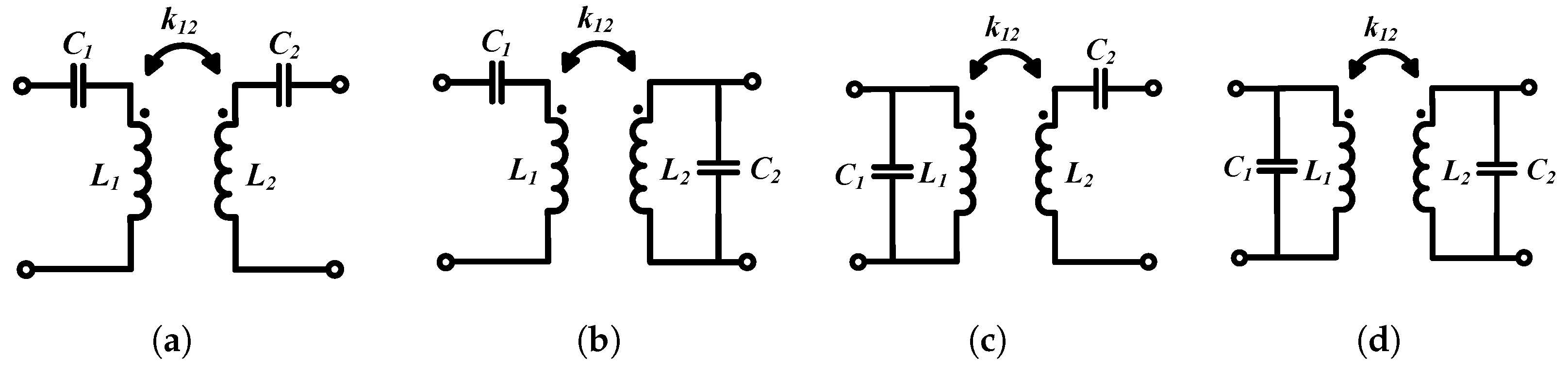
A simplified lumped parameter model of a WPT system using FHA is shown in Figure 4a. The transmitter consists of an AC voltage source, a compensation capacitor, and the transmitting coil. The AC voltage source is most commonly a high-frequency inverter or a power amplifier which drives the transmitter coil. The most used compensation network is the series-series configuration but some other widely used networks include LCL [62], LCC [63][64], LC/S [65], etc. The series resistance is the sum of coil resistance, ESR of compensating capacitors, and any resistance from the source. The receiver comprises a coil, a compensating capacitor, and a load. The load can be AC or DC. In case it is a DC load, which is typically the case with battery charging applications, then the load is preceded by a rectifier and a power conditioning unit (typically a DC-DC converter). The coupled inductance can also be modeled as two dependent voltage sources on the transmitter and receiver as shown in Figure 4b. Other commonly used models of the WPT coils are the T-transformer network and the cantilever model; however, the coupled inductor model is the most widely used.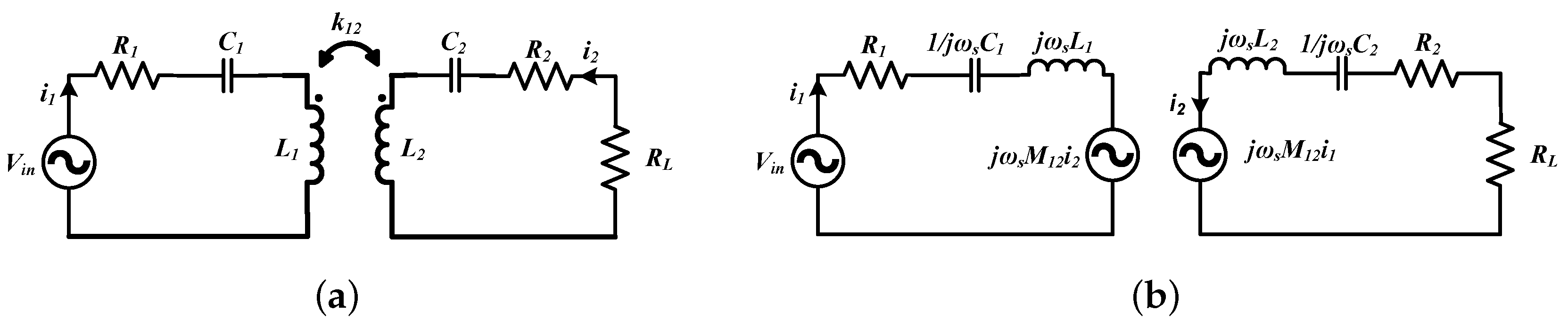
2.2. Compensation Networks
2.3. Maximizing Power Transfer between the Transmitter and Receiver
2.4. Efficiency Optimization Techniques
2.5. WPT Systems with Multiple Coils
2.5.1. Intermediate Multiple Coils Acting as Repeaters or Domino Resonators
- 1.
-
Multiple intermediate coils introduce more degrees of freedom which can be utilized for improving efficiency or making the wireless link less sensitive to coupling variations.
- 2.
-
The intermediate coils can also act as effective impedance matching elements [67] on both the source and load sides.
2.5.2. Multiple Transmitter Coil Systems
Multiple transmitter coils are mostly applied in two areas: (a) dynamic WPT and (b) systems that require misalignment tolerance. In dynamic WPT systems, the receiver is in motion. Multiple transmitter coils are connected to one power source and have to be powered effectively based on the location of the receiver. The current flows in the transmitter coils to which the receiver is aligned, while other transmitter coils are not charged. By using multiple transmitter coils, one can also generate a nearly uniform magnetic field over a surface, allowing some tolerance to misalignment of the receiver [66].2.5.3. Multiple Receiver Coil Systems
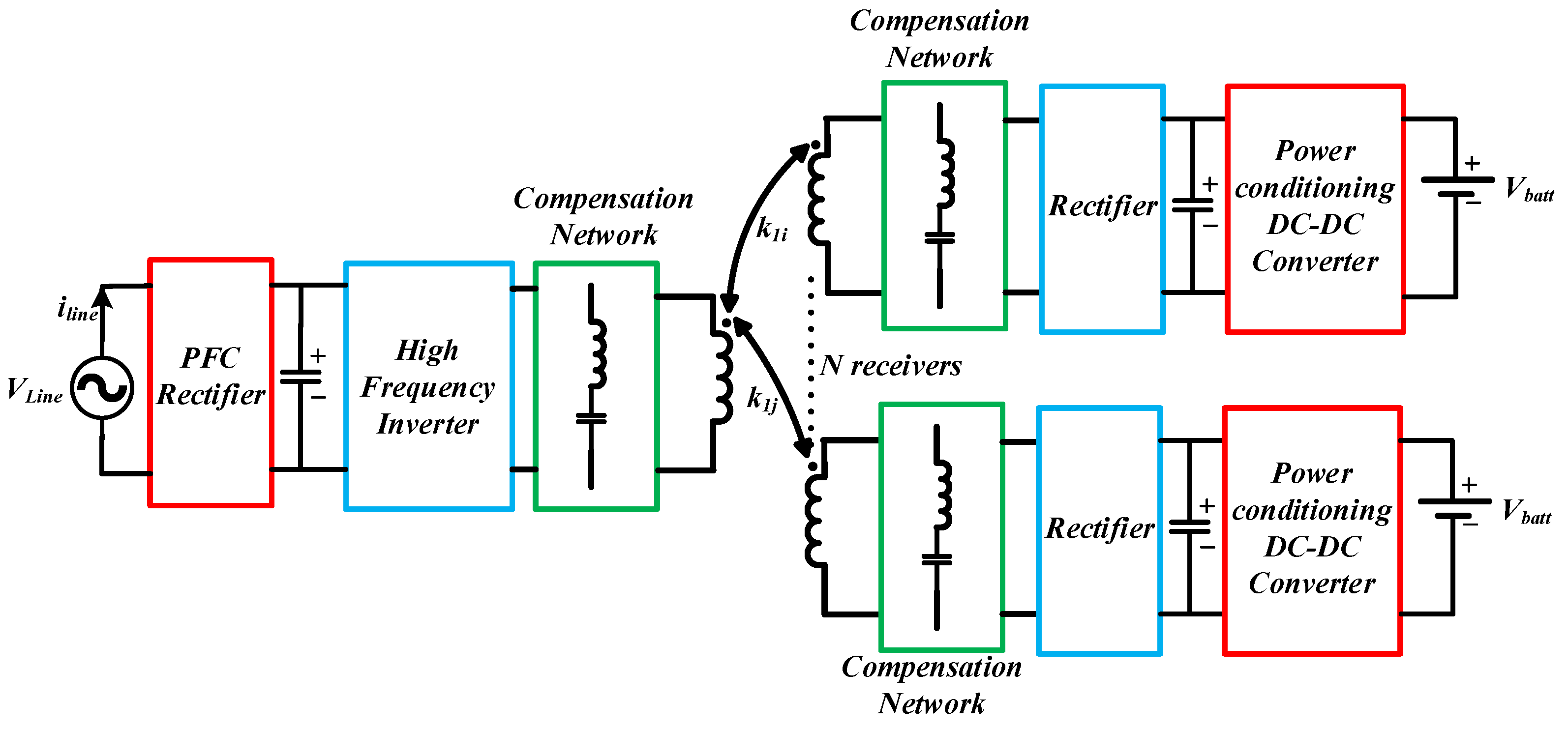
In some WPT applications, multiple receivers are needed to be powered simultaneously from a single transmitter system. As shown in Section 2.1, adding more receivers can improve link efficiency. However, the addition of multiple receivers reduces their coupling coefficients with the transmitter because of spatial constraints. Hence, quality factors of the coils need to be increased, which can be achieved by operating the system in the MHz range. In practice, there are many uncertainties with multiple receiver systems, such as variations in the coupling and load and addition or removal of receivers. Therefore, it is necessary to have a robust system with proper design and control. The most common control objective is to maximize the system’s efficiency while maintaining voltage regulation at the output. To ensure voltage regulation at the output of the receivers, a DC-DC converter is commonly used [68][69]. Voltage regulation can be maintained with wide variations in load or coupling if the input voltage to the system is sufficiently large. However, a large input voltage leads to inefficient operation of the system.3. Inverter, Rectifier, and Compensation Topologies for Wireless Power Transfer
3.1. Inverter Topologies
To ensure the high efficiency of the inverters, losses in the semiconductor devices must be minimized. The major sources of power losses in semiconductor devices are conduction losses and switching losses. When the switching frequency is increased, the optimal load resistance in Equation (6) also increases. Thus, for a given output power, one can operate at a higher voltage and lower current on the transmitter side. This reduces conduction losses on the switch, since they are proportional to the square of the current. Switching losses are proportional to the frequency of operation and can be significant at MHz frequencies. However, switching losses can be almost eliminated using soft-switching techniques. There are several types of DC-AC power inverters in the MHz frequency range which can achieve soft-switching such as the class D, class E, and class EF inverter topologies.3.1.1. Class D Topology
The two switches have a complementary operation to one another, with a suitable dead time, and produce a square wave voltage across the bottom switch. Class D inverters are used mainly in low-power systems and are widely used with the Qi standard. They can operate over a large load range with soft switching if the switching frequency is above the resonant frequency of the transmitter, i.e., the resonant tank current is inductive (lagging) with respect to the tank input voltage. This increases the VA requirement of the power source. Another disadvantage of the Class D topology is the use of more switches (two for half-bridge and four for full-bridge).3.1.2. Class E Topology
The Class E circuit has only one switch that is low-side referenced, which makes it easier for driving the inverter at high frequencies [70]. If the load network is slightly inductive, the standard Class E circuit allows soft switching. A major drawback of the Class E topology is that the voltage stress across the switch is nearly 3.56 times that of the input voltage when operating under optimum conditions. Furthermore, in the Class E topology, the transmitter coil current must flow through the transistor. This switch current can be reduced by using a parallel resonance. One way to minimize the VA rating of the switch is by using a “semi resonance” tank [71].3.1.3. Class EF Topology
A resonant branch, L2and C2, is added across the switch, which offers an extra degree of freedom to the designer to achieve ZVS throughout the entire load range. The extra LC resonant tank also reduces the voltage and current stresses across the switch and improves the efficiency of the inverter as well as increases the power handling capability. The added network can be tuned to twice the switching frequency (or 2nd harmonic), in which case the modified topology is known as the Class EF2 or Class ϕ2 inverter [72].3.2. Rectifier Topologies
From the time reversal duality [73] concept, rectifier topologies can be derived from inverter topologies and vice versa. For low current applications (<2 A), rectifiers are normally made with diodes, which could lead to significant losses due to hard switching and reverse recovery. Hence, soft-switched (or resonant) topologies which do not have high semiconductor stresses need to be used.3.3. Transmitter Topologies with Constant Current Output
In multiple receiver systems with a voltage-source-type transmitter, the change in load on one receiver affects the amount of power delivery to the others. This is because the power delivery to each receiver is directly proportional to the reflected resistance on the transmitter. The current in the transmitter varies with changes in the reflected resistance with movement or load variations in one receiver, and hence the power transferred to all the receivers can change. Ideally, if the transmitter is a current source and the cross-coupling among the receivers is negligible, the power delivered to each load is only dependent on the impedance reflected to the transmitter. Hence, a decoupled power transfer to the receiver loads can be ensured by using a constant current topology on the transmitter side.4. Coil Design
4.1. Improving Coupling Coefficient between Coils
The coupling coefficient between WPT coils depends on the coil shapes and sizes, the distance and alignment between them, and the type of material used for the conductor. Circular coils are the most common form of WPT coils because of their symmetry and ease of fabrication. The self-inductance of circular spiral coils can be calculated using the circular loop approximation [74]. The mutual inductance between the coils can be calculated by modeling the circular spirals as a set of filamentary circular loops [75]. Other common coil forms include square and rectangular types. Simple expressions for planar spiral inductances (square, hexagonal, octagonal, and circular) have been derived in [76] using a modified Wheeler formula, current sheet approximation, and data fitting. The expressions were found to be accurate within a 5%error margin. The self-inductance of the coil required for a particular application also determines its size. Some applications also have geometric constraints that the coils must adhere to. For example, the receiver coil size in phones and wearables depends on the space available inside the enclosure. The coupling coefficient between coils can be measured using a two-port network analyzer.
4.2. Improving the Quality Factor of Coils
The quality factor of the coil can be improved by reducing the AC resistance of the windings. Based on the operating frequency, the winding conductor can be solid, foil, tubular, or Litz. High-frequency eddy currents induced in a current-carrying conductor at high frequencies can cause conduction losses. Eddy currents can be induced by time-varying magnetic fields. At high frequencies, currents mostly flow near the surface of the conductors (depending on the skin depth at that frequency), leaving the inner part with almost zero current flow. This phenomenon increases the AC resistance of the conductor and is called the skin effect. When the radius of the conductor is smaller than the skin depth, current flows uniformly through the cross-section of the wire. The flow of current in close-by conductors often restricts the distribution of currents in the wires of the coils to smaller regions. This phenomenon is called the proximity effect and it increases the effective resistance of the coils, which increases with frequency. Tightly wound coils with a very low pitch between the turns have a low quality factor due to the prominence of proximity losses. Foil wires are widely used in inductive WPT systems. Copper foils with a thickness close to skin depth in the MHz frequency range (copper skin depth is between 65 and 15 µm in the 1–20 MHz range) are commercially available. They can also be manufactured in printed circuit boards (PCBs).4.3. Self-Resonant Coils
Series compensation of coils is most widely used for WPT. When designing high Q systems, the resonant voltage may be very high across the capacitors which may lead to a breakdown of discrete commercially available capacitors. One method to reduce the voltage stresses is by using large arrays of capacitors. However, this increases the cost and reduces the power density of the system. Furthermore, it introduces stray impedances, especially for high Q coils when the capacitance required is in the low pF range. Another approach is to use the self-resonance of the coil, where the intrinsic electric field of the coil resonates with the magnetic field. The analysis and design of a series self-resonant coil has been demonstrated in [77], where two identical planar coils were separated by a layer of dielectric material. One terminal of each coil is connected to the AC source while the other terminals are left open.4.4. Omnidirectional Wireless Power Transfer
Planar transmitter coils produce magnetic fields in a fixed direction. Hence, the movement of the receiver coil from its desired location can reduce the flux linkage with the transmitter coil and diminish the power transferred to the load. To expand the positional freedom of wireless power transfer, omnidirectional wireless charging has been gaining a lot of interest over the past few years [78][79][80][81][82][83][84][85][86]. Based on the number of sources used for the transmitter, omnidirectional WPT systems can be classified into two types:-
Multiple power sources used for multiple transmitter coils. Based on the location of the receiver, the amplitude and phase of the coil currents are controlled dynamically. This requires complicated external control circuits for measurements and feedback and can become expensive in practice.
-
A single power source is connected to the transmitter. This technique is simpler to implement. However, the system can have blind spots where the coupling is much less.
4.5. Use of Ferrite Cores
Using soft magnetic materials such as ferrite cores is one method of increasing the coupling coefficient among the coils. The high permeability of the ferrite core can be used to shape the field produced between the coils and increase the coupling between them. Ferrites also increase the self-inductance of the coils. Ferrite materials, which have high saturation flux density, high bulk resistivity, high permeability, and low AC power losses, are beneficial for WPT systems. NiZn and MnZn are the most commonly used ferrites in WPT. MnZn has a high saturation flux density and a high permeability, while NiZn ferrite has a lower permeability and a high bulk resistivity. A ferrite with high permeability increases the magnetic energy storage per unit self-inductance of the coil. A ferrite with high bulk resistivity reduces the high-frequency-induced eddy and displacement currents. The core loss in ferrites for sinusoidal excitation depends on the frequency and magnetic flux density in the core. Hence, ferrites are popular in frequency ranges below the MHz range.4.6. Solenoidal Receiver Coils for Multiple Receiver Systems
Spiral receiver coils placed face down on the transmitter pad lead to poor utilization of the transmitter area because of the increased surface area required for the receivers. A spiral or double-D transmitter coil can be used with solenoidal receiver coils to increase the arrangement density of the receivers [87].5. Foreign Object Detection
Foreign objects kept near the AC magnetic flux generated by the WPT coils can absorb power if they are of metallic or ferromagnetic nature. Induced eddy currents circulate within the materials, resulting in a conduction loss and a temperature rise. These currents increase the temperature of the foreign material and could become a potential safety concern. Foreign objects can be “friendly” or “unwanted”. Friendly foreign objects are generally parts of the charging devices that may absorb some power. Unwanted objects are external ones that are not part of the device, such as coins, keys, ornaments, utensils, etc. Some types of foreign object detection methods are given below [66]:- 1.
-
Power difference method—The transmitted and received power are monitored. If the difference between them is higher than a set threshold, it indicates the presence of foreign objects. In this case, the transmitter stops delivering power to the receiver circuit.
- 2.
-
Sensor method—Temperature and/or metal sensors are used to detect any anomaly in the transmission path. Anomalies detected by the sensors are communicated to the transmitter using load modulation. If the temperature sensed is higher than the threshold or there are metals present in the transmission path, the control circuit will shut down the power transmission.
- 3.
-
Transient energy decay method—The transmitter is powered for a short time and then disabled to check the rate of transient energy decay. If this rate exceeds the set threshold, the presence of a foreign object is confirmed and the system is shut down.
6. EMC/EMI Issues and EMF Safety in Near-Field Wireless Power Transfer
6.1. De-Sense Caused by In-Band Noise and Shielding in Smartphones
Every smartphone must satisfy some receiver sensitivity criteria (wireless WAN antenna sensitivity) to be approved by the FCC. The EMI noise produced by the system must be reduced at the antennae to maintain an appropriate signal-to-noise ratio. Furthermore, any shielding near the antennae can cause a degradation in sensitivity (de-sense). At low frequencies (near 110–205 kHz), ferrites used as shields reduce the receiver sensitivity by about 12 dB. This could worsen cell reception in low-signal areas. Requirements regarding de-sense are much harder to meet than EMI compatibility [88]. These are easier to meet at high frequencies because 6.78 MHz antennae cause a sensitivity reduction of only 2dB.6.2. EMF Safety Standards
The currents in the WPT coils produce significant magnetic fields (H-field), electric fields (E-field), and electromagnetic fields (EMF) in the environment that can induce adverse health effects in the human body. Therefore, ensuring that WPT systems remain within the safety limits for human exposure is very important. Some of the existing international standards for safety from EMF exposure are:- 1.
-
International Commission on Non-Ionizing Radiation Protection (ICNIRP) Guidelines for Limiting Exposure to Time-varying E-field, H-field, and EMF (up to 300 GHz) [89].
- 2.
-
IEEE Standard for Safety Levels with Respect to Human Exposure to Radio Frequency EMF (3 kHz to 300 GHz) [90].
6.3. Studies on EMF Safety
EMF exposure limits in humans from wireless power were evaluated by using numerical analyses and measurements in [91]. MHz WPT systems via near-field coupling over a few meters distances were examined based on SAR levels. Four different anatomical models were used (two adults, Duke and Ella, and two children, Eartha and Thelonious) and exposed to a WPT transmitter operating at 8 MHz along the coronal, axial, and sagittal orientations. The models did not distort the H-field in the simulation; however, the resonant frequency of the coils was decreased from 8 MHz to 7.6 MHz.7. Conclusions
High-frequency operation of WPT systems leads to miniaturization of the components and a higher efficiency. For this reason, various soft-switched topologies such as Class D, E, EF, etc., are used to operate the WPT systems at high frequencies in the megahertz range. WBG and ultra-WBG devices can be used for very high frequency operation. Compensation topologies reduce the VA rating of the transmitter and can also infer voltage source or constant source characteristics to the inverters. Constant current source inverters are particularly useful when using multiple receivers since they ensure decoupled power transfer to the receivers. Coil design is an integral part of a WPT system since a proper design can optimize the k-Q product of the system and increase the link efficiency. The k-Q product can be improved by increasing the coupling between the transmitting and receiving coils and by improving the quality factor of the coils. WPT coils are intentional sources of EMI, and hence EMF safety becomes an issue of concern. EMF safety limits have not been fully standardized, and only the acute (short-term) effects have been examined. More research is needed to understand the long-term effects of such field exposures.
References
- Nikola Tesla 1857–1943. Proc. IRE 1943, 31, 194–1943.
- Tesla, N. High frequency oscillators for electro-therapeutic and other purposes. Proc. IEEE 1999, 87, 1282.
- Garnica, J.; Chinga, R.A.; Lin, J. Wireless Power Transmission: From Far Field to Near Field. Proc. IEEE 2013, 101, 1321–1331.
- Litz Wire. Available online: https://mwswire.com/specialty-wire/litz-wire/ (accessed on 12 January 2023).
- Ghahary, A.; Cho, B.H. Design of a transcutaneous energy transmission system using a series resonant converter. In Proceedings of the 21st Annual IEEE Conference on Power Electronics Specialists, San Antonio, TX, USA, 11–14 June 1990; pp. 1–8.
- Joun, G.B.; Cho, B.H. An energy transmission system for an artificial heart using leakage inductance compensation of transcutaneous transformer. IEEE Trans. Power Electron. 1998, 13, 1013–1022.
- Elliott, G.A.J.; Boys, J.T.; Green, A.W. Magnetically coupled systems for power transfer to electric vehicles. In Proceedings of the 1995 International Conference on Power Electronics and Drive Systems. PEDS 95, Singapore, 21–24 February 1995; Volume 2, pp. 797–801.
- Green, A.W.; Boys, J.T. 10 kHz inductively coupled power transfer-concept and control. In Proceedings of the Fifth International Conference on Power Electronics and Variable-Speed Drives, London, UK, 26–28 October 1994; pp. 694–699.
- Hui, S.Y.R. Planar Inductive Battery Charger. UK Patent GB2389720B, 7 September 2005.
- Kim, C.G.; Seo, D.H.; You, J.S.; Park, J.H.; Cho, B.H. Design of a contactless battery charger for cellular phone. In Proceedings of the Fifteenth Annual IEEE Applied Power Electronics Conference and Exposition (Cat. No.00CH37058), New Orleans, LA, USA, 6–10 February 2000; Volume 2, pp. 769–773.
- Jang, Y.; Jovanovic, M.M. A contactless electrical energy transmission system for portable-telephone battery chargers. IEEE Trans. Ind. Electron. 2003, 50, 520–527.
- Wong, C.S.; Duzgoren-Aydin, N.S.; Aydin, A.; Wong, M.H. Evidence of excessive releases of metals from primitive e-waste processing in Guiyu, China. Environ Pollut. 2007, 148, 62–72.
- Sample, A.P.; Yeager, D.J.; Powledge, P.S.; Mamishev, A.V.; Smith, J.R. Design of an RFID-Based Battery-Free Programmable Sensing Platform. IEEE Trans. Instrum. Meas. 2008, 57, 2608–2615.
- Ullah, M.A.; Keshavarz, R.; Abolhasan, M.; Lipman, J.; Esselle, K.P.; Shariati, N. A Review on Antenna Technologies for Ambient RF Energy Harvesting and Wireless Power Transfer: Designs, Challenges and Applications. IEEE Access 2022, 10, 17231–17267.
- Ishino, S.; Takano, I.; Yano, K.; Shinohara, N. Frequency-division techniques for microwave power transfer and wireless communication system with closed waveguide. In Proceedings of the 2016 IEEE Wireless Power Transfer Conference (WPTC), Aveiro, Portugal, 5–6 May 2016; pp. 1–4.
- Putra, A.W.S.; Kato, H.; Maruyama, T. Hybrid Optical Wireless Power and Data Transmission System. In Proceedings of the IEEE PELS Workshop on Emerging Technologies: Wireless Power Transfer (WoW), Seoul, Republic of Korea, 15–19 November 2020; pp. 374–376.
- So, E.; Yeon, P.; Chichilnisky, E.J.; Arbabian, A. An RF-Ultrasound Relay for Adaptive Wireless Powering Across Tissue Interfaces. IEEE J. Solid-State Circuits 2022, 57, 3429–3441.
- Chang, C.K.; Da Silva, G.G.; Kumar, A.; Pervaiz, S.; Afridi, K.K. 30 W capacitive wireless power transfer system with 5.8 pF coupling capacitance. In Proceedings of the IEEE Wireless Power Transfer Conference (WPTC), Boulder, CO, USA, 13–15 May 2015; pp. 1–4.
- Kim, M.; Choi, J. Design of High-frequency Resonant Inverter for Capacitive Wireless Power Transfer. In Proceedings of the IEEE 21st Workshop on Control and Modeling for Power Electronics (COMPEL), Aalborg, Denmark, 9–12 November 2020; pp. 1–7.
- Kumar, A.; Pervaiz, S.; Chang, C.K.; Korhummel, S.; Popovic, Z.; Afridi, K.K. Investigation of power transfer density enhancement in large air-gap capacitive wireless power transfer systems. In Proceedings of the IEEE Wireless Power Transfer Conference (WPTC), 13–15 May 2015; pp. 1–4.
- Rose, J.A.; Cates, J.A. Capacitive Charge Coupling with Dual Connector Assemblies and Charging System. U.S. Patent 5 714 864, 3 February 1998.
- Liu, C.; Hu, A.P. Steady state analysis of a capacitively coupled contactless power transfer system. In Proceedings of the IEEE Energy Conversion Congress and Exposition, San Jose, CA, USA, 20–24 September 2009; pp. 3233–3238.
- Wahab, A.; Chong, T.E.; Min, L.K. Wireless pointing device using capacitive coupling. In Proceedings of the 1997 IEEE International Symposium on Consumer Electronics (Cat. No.97TH8348), Singapore, 2–4 December 1997; pp. 149–152.
- Kline, M.; Izyumin, I.; Boser, B.; Sanders, S. Capacitive power transfer for contactless charging. In Proceedings of the Twenty-Sixth Annual IEEE Applied Power Electronics Conference and Exposition (APEC), Fort Worth, TX, USA, 6–11 March 2011; pp. 1398–1404.
- Choi, J.; Tsukiyama, D.; Rivas, J. Comparison of SiC and eGaN devices in a 6.78 MHz 2.2 kW resonant inverter for wireless power transfer. In Proceedings of the IEEE Energy Conversion Congress and Exposition (ECCE), Milwaukee, WI, USA, 18–22 September 2016; pp. 1–6.
- Choi, B.; Nho, J.; Cha, H.; Ahn, T.; Choi, S. Design and implementation of low-profile contactless battery charger using planar printed circuit board windings as energy transfer device. IEEE Trans. Ind. Electron. 2004, 51, 140–147.
- Lillholm, M.B.; Dou, Y.; Chen, X.; Zhang, Z. Analysis and Design of 10-MHz Capacitive Power Transfer with Multiple Independent Outputs for Low-Power Portable Devices. IEEE J. Emerg. Sel. Top. Power Electron. 2022, 10, 149–159.
- Yang, L.; Li, X.; Liu, S.; Xu, Z.; Cai, C. Analysis and Design of an LCCC/S-Compensated WPT System with Constant Output Characteristics for Battery Charging Applications. IEEE J. Emerg. Sel. Top. Power Electron. 2021, 9, 1169–1180.
- Hui, S.Y.R.; Ho, W.C. A new generation of universal contactless battery charging platform for portable consumer electronic equipment. In Proceedings of the IEEE 35th Annual Power Electronics Specialists Conference (IEEE Cat. No.04CH37551), Aachen, Germany, 20–25 June 2004; Volume 1, pp. 638–644.
- Zhong, W.X.; Liu, X.; Hui, S.Y.R. A Novel Single-Layer Winding Array and Receiver Coil Structure for Contactless Battery Charging Systems with Free-Positioning and Localized Charging Features. IEEE Trans. Ind. Electron. 2011, 58, 4136–4144.
- Patil, D.; McDonough, M.K.; Miller, J.M.; Fahimi, B.; Balsara, P.T. Wireless Power Transfer for Vehicular Applications: Overview and Challenges. IEEE Trans. Transp. Electrif. 2018, 4, 3–37.
- Regensburger, B.; Sinha, S.; Kumar, A.; Maji, S.; Afridi, K.K. High-Performance Multi-MHz Capacitive Wireless Power Transfer System for EV Charging Utilizing Interleaved-Foil Coupled Inductors. IEEE J. Emerg. Sel. Top. Power Electron. 2022, 10, 35–51.
- Chinthavali, M.; Onar, O.C.; Campbell, S.L.; Tolbert, L.M. Integrated charger with wireless charging and boost functions for PHEV and EV applications. In Proceedings of the IEEE Transportation Electrification Conference and Expo (ITEC), Dearborn, MI, USA, 14–17 June 2015; pp. 1–8.
- Wu, H.H.; Gilchrist, A.; Sealy, K.D.; Bronson, D. A High Efficiency 5 kW Inductive Charger for EVs Using Dual Side Control. IEEE Trans. Ind. Inform. 2012, 8, 585–595.
- Nguyen, H.T.; Alsawalhi, J.Y.; Al Hosani, K.; Al-Sumaiti, A.S.; Al Jaafari, K.A.; Byon, Y.J.; El Moursi, M.S. Review Map of Comparative Designs for Wireless High-Power Transfer Systems in EV Applications: Maximum Efficiency, ZPA, and CC/CV Modes at Fixed Resonance Frequency Independent From Coupling Coefficient. IEEE Trans. Power Electron. 2022, 37, 4857–4876.
- Kissin, M.L.G.; Ha, H.; Covic, G.A. A practical multiphase IPT system for AGV and roadway applications. In Proceedings of the IEEE Energy Conversion Congress and Exposition, Atlanta, GA, USA, 12–16 September 2010; pp. 1844–1850.
- Kanazawa, H.; Uwai, H.; Kiuchi, S.; Matsumoto, H. Receiver-Position-Based Unbalanced-Current Control for a Three- to Single-Phase Wireless Power Transfer System for AGVs. IEEE Trans. Ind. Electron. 2023, 70, 3245–3256.
- Zeng, Y.; Rong, C.; Lu, C.; Tao, X.; Liu, X.; Liu, R.; Liu, M. Misalignment Insensitive Wireless Power Transfer System Using a Hybrid Transmitter for Autonomous Underwater Vehicles. IEEE Trans. Ind. Appl. 2022, 58, 1298–1306.
- Choi, J.; Tsukiyama, D.; Tsuruda, Y.; Davila, J.M.R. High-Frequency, High-Power Resonant Inverter with eGaN FET for Wireless Power Transfer. IEEE Trans. Power Electron. 2018, 33, 1890–1896.
- Arteaga, J.M.; Aldhaher, S.; Kkelis, G.; Kwan, C.; Yates, D.C.; Mitcheson, P.D. Dynamic Capabilities of Multi-MHz Inductive Power Transfer Systems Demonstrated with Batteryless Drones. IEEE Trans. on Power Electron. 2019, 34, 5093–5104.
- Baker, M.W.; Sarpeshkar, R. Feedback Analysis and Design of RF Power Links for Low-Power Bionic Systems. IEEE Trans. Biomed. Circuits Syst. 2007, 1, 28–38.
- Mandal, S.; Sarpeshkar, R. Power-Efficient Impedance-Modulation Wireless Data Links for Biomedical Implants. IEEE Trans. Biomed. Circuits Syst. 2008, 2, 301–315.
- Li, P.; Principe, J.C.; Bashirullah, R. A Wireless Power Interface for Rechargeable Battery Operated Neural Recording Implants. In Proceedings of the International Conference of the IEEE Engineering in Medicine and Biology Society, New York, NY, USA, 30 August–3 September 2006; pp. 6253–6256.
- Rong, C.; Zhang, B.; Wei, Z.; Wu, L.; Shu, X. A Wireless Power Transfer System for Spinal Cord Stimulation Based on Generalized Parity–Time Symmetry Condition. IEEE Trans. Ind. Appl. 2022, 58, 1330–1339.
- Roy, S.; Azad, A.N.M.W.; Baidya, S.; Alam, M.K.; Khan, F. Powering Solutions for Biomedical Sensors and Implants Inside the Human Body: A Comprehensive Review on Energy Harvesting Units, Energy Storage, and Wireless Power Transfer Techniques. IEEE Trans. Power Electron. 2022, 37, 12237–12263.
- Choi, J.; Ooue, Y.; Furukawa, N.; Rivas, J. Designing a 40.68 MHz power-combining resonant inverter with eGaN FETs for plasma generation. In Proceedings of the IEEE Energy Conversion Congress and Exposition (ECCE), Portland, OR, USA, 23–27 September 2018; pp. 1322–1327.
- Elliott, G.A.J.; Covic, G.A.; Kacprzak, D.; Boys, J.T. A New Concept: Asymmetrical Pick-Ups for Inductively Coupled Power Transfer Monorail Systems. IEEE Trans. Magn. 2006, 42, 3389–3391.
- Wu, H.H.; Boys, J.; Covic, G.; Ren, S.; Hu, P. An AC processing pickup for IPT systems. In Proceedings of the IEEE Energy Conversion Congress and Exposition, San Jose, CA, USA, 20–24 September 2009; pp. 840–846.
- Keeling, N.A.; Covic, G.A.; Boys, J.T. A Unity-Power-Factor IPT Pickup for High-Power Applications. IEEE Trans. Ind. Electron. 2010, 57, 744–751.
- Hu, A.P.; Liu, C.; Li, H.L. A Novel Contactless Battery Charging System for Soccer Playing Robot. In Proceedings of the 15th International Conference on Mechatronics and Machine Vision in Practice, Auckland, New Zealand, 2–4 December 2008; pp. 646–650.
- Liu, J.; Xu, F.; Sun, C.; Loo, K.H. A Compact Single-Phase AC–DC Wireless Power Transfer Converter with Active Power Factor Correction. IEEE Trans. Ind. Electron. 2023, 70, 3685–3696.
- Liu, J.; Xu, F.; Sun, C.; Loo, K.H. A Soft-Switched Power-Factor-Corrected Single-Phase Bidirectional AC–DC Wireless Power Transfer Converter with an Integrated Power Stage. IEEE Trans. Power Electron. 2022, 37, 10029–10044.
- Jiang, L.; Costinett, D. A High-Efficiency GaN-Based Single-Stage 6.78 MHz Transmitter for Wireless Power Transfer Applications. IEEE Trans. Power Electron. 2019, 34, 7677–7692.
- Cochran, S.; Costinett, D. Wide-Range Stability of Concurrent Load Regulation and Frequency Synchronization for a 7-Level Switched Capacitor WPT Rectifier. In Proceedings of the IEEE PELS Workshop on Emerging Technologies: Wireless Power Transfer (WoW), San Diego, CA, USA, 1–4 June 2021; pp. 1–6.
- Fang, Y.; Pong, B.M.H.; Hui, R.S.Y. An Enhanced Multiple Harmonics Analysis Method for Wireless Power Transfer Systems. IEEE Trans. Power Electron. 2020, 35, 1205–1216.
- Laha, A.; Kalathy, A.; Jain, P. Frequency Domain Analysis of a Wireless Power Transfer System Operating in a Wide Load and Coupling Range Using Frequency Modulation of Inverter for Voltage Regulation. In Proceedings of the IEEE Applied Power Electronics Conference and Exposition (APEC), Houston, TX, USA, 20–24 March 2022; pp. 1891–1897.
- Fang, Y.; Pong, B.M.H. Multiple Harmonics Analysis for Variable Frequency Asymmetrical Pulsewidth-Modulated Wireless Power Transfer Systems. IEEE Trans. Industrial Electron. 2019, 66, 4023–4030.
- Laha, A.; Jain, P. Maximizing Efficiency while maintaining Voltage Regulation of Wireless Power Transfer Systems using a Buck-Boost Converter. In Proceedings of the IEEE Applied Power Electronics Conference and Exposition (APEC), Phoenix, AZ, USA, 14–17 June 2021; pp. 700–705.
- Safaee, A.; Woronowicz, K. Time-Domain Analysis of Voltage-Driven Series–Series Compensated Inductive Power Transfer Topology. IEEE Trans. Power Electron. 2017, 32, 4981–5003.
- Laha, A.; Jain, P. Time Domain Modelling of a Wireless Power Transfer System using a Buck-Boost Converter for Voltage Regulation. In Proceedings of the IEEE Wireless Power Transfer Conference (WPTC), San Diego, CA, USA, 1–4 June 2021; pp. 1–4.
- Laha, A. Modelling and Efficiency Optimization of Wireless Power Transfer Systems having One or Two Receivers. Master’s Thesis, Department of Electrical and Computer Engineering, Queen’s University, Kingston, ON, Canada, September 2020.
- Yao, Y.; Wang, Y.; Liu, X.; Lin, F.; Xu, D. A Novel Parameter Tuning Method for a Double-Sided LCL Compensated WPT System with Better Comprehensive Performance. IEEE Trans. Power Electron. 2018, 33, 8525–8536.
- Deng, J.; Mao, Q.; Wang, W.; Li, L.; Wang, Z.; Wang, S.; Guidi, G. Frequency and Parameter Combined Tuning Method of LCC–LCC Compensated Resonant Converter with Wide Coupling Variation for EV Wireless Charger. IEEE J. Emerg. Sel. Top. Power Electron. 2022, 10, 956–968.
- Deng, J.; Li, W.; Nguyen, T.D.; Li, S.; Mi, C.C. Compact and Efficient Bipolar Coupler for Wireless Power Chargers: Design and Analysis. IEEE Trans. Power Electron. 2015, 30, 6130–6140.
- Wang, Y.; Yao, Y.; Liu, X.; Xu, D.; Cai, L. An LC/S Compensation Topology and Coil Design Technique for Wireless Power Transfer. IEEE Trans. Power Electron. 2018, 33, 2007–2025.
- Hui, S.Y. Planar Wireless Charging Technology for Portable Electronic Products and Qi. Proc. IEEE 2013, 101, 1290–1301.
- Zhong, W.; Lee, C.K.; Hui, S.Y.R. General Analysis on the Use of Tesla’s Resonators in Domino Forms for Wireless Power Transfer. IEEE Trans. Ind. Electron. 2013, 60, 261–270.
- Li, H.; Li, J.; Wang, K.; Chen, W.; Yang, X. A Maximum Efficiency Point Tracking Control Scheme for Wireless Power Transfer Systems Using Magnetic Resonant Coupling. IEEE Trans. Power Electron. 2015, 30, 3998–4008.
- Fu, M.; Yin, H.; Liu, M.; Wang, Y.; Ma, C. A 6.78 MHz Multiple-Receiver Wireless Power Transfer System with Constant Output Voltage and Optimum Efficiency. IEEE Trans. Power Electron. 2018, 33, 5330–5340.
- Peng, K.; Santi, E. Class E resonant inverter optimized design for high frequency (MHz) operation using eGaN HEMTs. In Proceedings of the IEEE Applied Power Electronics Conference and Exposition (APEC), Charlotte, NC, USA, 15–19 March 2015; pp. 2469–2473.
- Pinuela, M.; Yates, D.C.; Lucyszyn, S.; Mitcheson, P.D. Maximizing DC-to-Load Efficiency for Inductive Power Transfer. IEEE Trans. Power Electron. 2013, 28, 2437–2447.
- Choi, J.; Liang, W.; Raymond, L.; Rivas, J. A High-Frequency Resonant Converter Based on the Class Phi2 Inverter for Wireless Power Transfer. In Proceedings of the IEEE 79th Vehicular Technology Conference (VTC Spring), Seoul, Republic of Korea, 18–21 May 2014; pp. 1–5.
- Hamill, D.C. Class DE inverters and rectifiers for DC-DC conversion. In Proceedings of the PESC Record. 27th Annual IEEE Power Electronics Specialists Conference, Baveno, Italy, 23–27 June 1996; pp. 854–860.
- Zierhofer, C.M.; Hochmair, E.S. Geometric approach for coupling enhancement of magnetically coupled coils. IEEE Trans. Biomed. Eng. 1996, 43, 708–714.
- Akyel, C.; Babic, S.; Mahmoudi, M. Mutual Inductance Calculation for Non-Coaxial Circular Air Coils with Parallel Axes. Prog. Electromagn. Res. 2009, 91, 287–301.
- Mohan, S.S.; Hershenson, M.D.M.; Boyd, S.P.; Lee, T.H. Simple accurate expressions for planar spiral inductances. IEEE J. Solid-State Circuits 1999, 34, 1419–1424.
- Li, J.; Costinett, D. Analysis and design of a series self-resonant coil for wireless power transfer. In Proceedings of the IEEE Applied Power Electronics Conference and Exposition (APEC), San Antonio, TX, USA, 4–8 March 2018; pp. 1052–1059.
- Allama, O.; Habaebi, M.H.; Khan, S.; Elsheikh, E.A.A.; Suliman, F.E.M. 2D Omni-Directional Wireless Power Transfer Modeling for Unmanned Aerial Vehicles with Noncollaborative Charging System Control. Electronics 2021, 10, 2858.
- Houran, M.A.; Yang, X.; Chen, W.; Li, X. Design and analysis of coaxial cylindrical WPT coils for two-degree-of-freedom applications. J. Phys. Appl. Phys. 2020, 53, 495004.
- Ha-Van, N.; Liu, Y.; Jayathurathnage, P.; Simovski, C.R.; Tretyakov, S.A. Cylindrical Transmitting Coil for Two-Dimensional Omnidirectional Wireless Power Transfer. IEEE Trans. Ind. Electron. 2022, 69, 10045–10054.
- Lin, D.; Zhang, C.; Hui, S.Y.R. Mathematical Analysis of Omnidirectional Wireless Power Transfer—Part-I: Two-Dimensional Systems. IEEE Trans. Power Electron. 2017, 32, 625–633.
- Lin, D.; Zhang, C.; Hui, S.Y.R. Mathematic Analysis of Omnidirectional Wireless Power Transfer—Part-II Three-Dimensional Systems. IEEE Trans. Power Electron. 2017, 32, 613–624.
- Ng, W.M.; Zhang, C.; Lin, D.; Hui, S.Y.R. Two- and Three-Dimensional Omnidirectional Wireless Power Transfer. IEEE Trans. Power Electron. 2014, 29, 4470–4474.
- Feng, J.; Li, Q.; Lee, F.C.; Fu, M. Transmitter Coils Design for Free-Positioning Omnidirectional Wireless Power Transfer System. IEEE Trans. Ind. Inform. 2019, 15, 4656–4664.
- Kim, J.; Kim, D.H.; Choi, J.; Kim, K.H.; Park, Y.J. Free-Positioning Wireless Charging System for Small Electronic Devices Using a Bowl-Shaped Transmitting Coil. IEEE Trans. Microw. Theory Tech. 2015, 63, 791–800.
- Zhang, Z.; Zhang, B. Angular-Misalignment Insensitive Omnidirectional Wireless Power Transfer. IEEE Trans. Ind. Electron. 2020, 67, 2755–2764.
- Shao, Y.; Liu, M.; Ma, C. A Multi-Receiver MHz WPT System with Hybrid Coupler. In Proceedings of the IEEE PELS Workshop on Emerging Technologies: Wireless Power Transfer (WoW), San Diego, CA, USA, 1–4 June 2021; pp. 1–6.
- Jeong, N.S.; Carobolante, F. Wireless Charging of a Metal-Body Device. IEEE Trans. Microw. Theory Tech. 2017, 65, 1077–1086.
- International Commission on Non-Ionizing Radiation Protection (ICNIRP). Guidelines for limiting exposure to electromagnetic fields (100 kHz to 300 GHz). Health Phys. 2020, 118, 483–524.
- IEEE Std C95.1-2005; IEEE Standard for Safety Levels with Respect to Human Exposure to Radio Frequency Electromagnetic Fields, 3 kHz to 300 GHz; Revision of IEEE Std C95.1-1991. IEEE: Piscataway, NJ, USA, 2006; pp. 1–238.
- Christ, A.; Douglas, M.G.; Roman, J.M.; Cooper, E.B.; Sample, A.P.; Waters, B.H.; Smith, J.R.; Kuster, N. Evaluation of Wireless Resonant Power Transfer Systems with Human Electromagnetic Exposure Limits. IEEE Trans. Electromagn. Compat. 2013, 55, 265–274.