 +1 credit
| Version | Summary | Created by | Modification | Content Size | Created at | Operation |
|---|---|---|---|---|---|---|
| 1 | Maria João Regufe | + 4647 word(s) | 4647 | 2021-04-30 05:32:32 | | | |
| 2 | Conner Chen | -7 word(s) | 4640 | 2021-05-11 05:28:58 | | |
Video Upload Options
Energy from fossil fuels combustion always generates carbon dioxide, leading to a considerable environmental concern with the values of CO2 produced in the world. The increase in emissions leads to a significant challenge in reducing the quantity of this gas in the atmosphere. To decrease this problem, green and efficient solutions have been extensively studied, such as Carbon Capture Utilization and Storage (CCUS) processes. Broadly recognized as having an enormous potential to meet climate change targets, CCS and CCUS appear as solutions to deliver low carbon heat and power, decarbonize the industry, and, more recently, facilitate the net removal of CO2 from the atmosphere.
1. CO2 Emissions
In 2019, global energy-related CO2 emissions reached 33 gigatonnes (Gt), approximately [1]. This resulted mainly from a sharp decline in CO2 emissions from the power sector in advanced economies (Australia, Canada, Chile, European Union, Iceland, Israel, Japan, Korea, Mexico, Norway, New Zealand, Switzerland, Turkey, and United States.), because of the expanding role of renewable sources (mainly wind and solar photovoltaic systems), fuel switching from coal to natural gas, and higher nuclear power output. However, the total emissions, in the rest of the world, increased.
Figure 1 shows the gigatonnes of CO2 emitted by developed countries, the rest of the world, and total emissions from 1990 until 2019 [2].
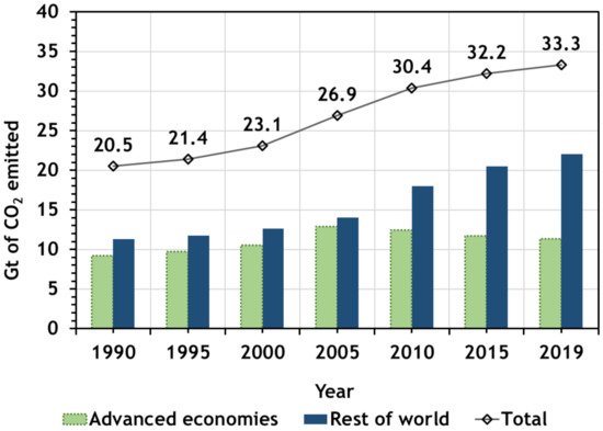
Figure 1. CO2 emissions by countries for a period from 1990 until 2019 (adapted from Agency [2]).
Figure 2 shows the global greenhouse gas emissions (%) by sector in 2020 [2]. The economic sector which had the highest share of carbon dioxide emissions from fossil fuels and cement was the power sector. With a 44% of emissions, this was more than the combined share of both industry and surface transport. These three sectors of the economy make up the majority of the world’s CO2 emissions.
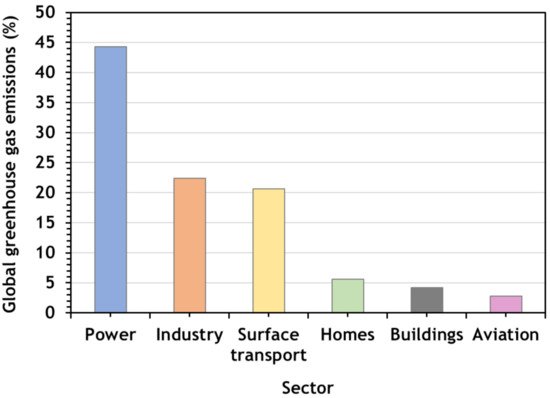
Figure 2. Global greenhouse gas emissions by sector in 2020 (adapted from Tiseo [3]).
Covid-19 had an enormous impact on energy demand and, therefore, on CO2 emissions. The drastic curtailment of global economic activity and mobility during the first quarter of 2020 pushed down global energy demand by about 3.8% compared with the first quarter of 2019 [1]. CO2 emissions were about 5% lower in Q1 2020 than in Q1 2019, almost twice as large as all previous declines since the end of World War II. By sectors, emissions from coal, oil, and natural gas declined about 8, 4.5, and 2.3%, respectively. By regions, a considerable decrease of CO2 emissions was observed: −8% in China, −8% in the European Union (EU), and −9% in the United States [1]. However, this decline was punctual; it will not be enough to resolve climate change problems.
In April 2020, McKinsey Global Institute published an overview of several scenarios of projected global CO2 emissions that helps to understand the future. Climate Action Tracker [4] also provide these data. The scenarios are shown in Figure 3, where global CO2 emissions in each scenario are projected. All pathways include energy-related emission, industry-process emissions (e.g., from cement production), emissions from deforestation and waste, and negative emissions (e.g., from reforestation and carbon-removal technologies such as bioenergy with carbon capture and storage, and direct air carbon capture and storage). Emissions from biotic feedbacks (e.g., from permafrost thawing, wildfires) were not considered. The red lines represent warming projections if policies are not applied: the lower bound is a “continued growth” pathway based on the IEA’s World Energy Outlook 2019 current policies scenario; the higher bound is based on IPCC’s Representative Concentration Pathway 8.5 [5]. It is possible to observe the need for immediate reduction of GHG emissions.
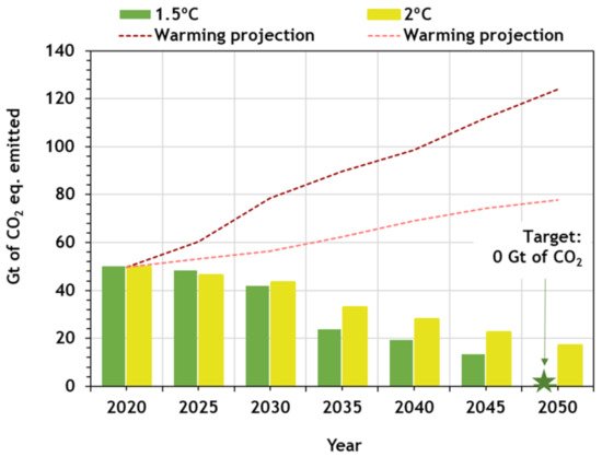
Figure 3. Projected global CO2 emissions per scenario (adapted from Climate Action Tracker [4]).
According to this study, if no changes are applied, the continued growth will lead to about 120 Gt equivalent of CO2 emitted per year in 2050. However, to achieve the 1.5 °C pathway of the Paris Agreement, the CO2 emissions should be 0 Gt by then.
2. Carbon Capture (Utilization) and Storage (CCUS or CCS)
Basically, carbon capture and storage (CCS) consists of the separation and concentration of CO2 from power generation plants or industrial processes, its pressurization and transportation, via ship or pipeline, to specific locations where it should be permanently stored deep underground, in geological formations (depleted oil or gas reservoirs or deep saline aquifers) [6][7]. This technology has been identified as a priority, being a critical emissions reduction technology that can be applied across the energy system, expecting to play an essential role in meeting the global warming targets [8][9][10].
CCS is often used interchangeably with the term Carbon Capture, Utilization, and Storage (CCUS). The difference between the two terms presented is the ‘utilization’ word, which refers to the use of carbon for other applications. CCUS can contribute to almost one-fifth of the emissions reductions needed across the industry sector. CCUS will play a key role in reducing CO2 emissions from fossil-fuel-based power generation and is the only option available to reduce direct emissions from other industrial point sources significantly [11]. It was estimated that the use of CCUS would address up to 32% of global CO2 emissions reduction by 2050 [12]. More than 28 Gt of CO2 could be captured from industrial processes until 2060, the majority of it from the cement, steel, and chemical subsectors [13].
CCS and CCUS technologies are developed slowly, mainly as a result of high costs and unsupportive policy and regulatory frameworks in many countries [14].
The economic penalty of the capture is the crucial obstacle to CCS/CCUS implementation. The efficiency of the CO2 capture must be increased in the capture step of the processes, as it is estimated that the capture step is responsible for 60% to 80% of the overall CCS/CCUS economic penalty [15][6]. The capture part of the process represents the main promise for cost reduction and focuses on most of the research efforts. CCS or CCUS is far from the ideal solution because it does not directly use green fuels. Still, it is the only technology capable of maintaining the utilization of the existing power plants.
In these types of processes, CO2 capture technologies can be classified into three groups: pre-combustion systems, post-combustion systems, and oxy-fuel or oxy-combustion processes. The first and second systems depend on whether carbon dioxide is removed before or after fuel is burned. In the third, pure oxygen rather than air is used for combustion [16]. Figure 4 shows a brief scheme of methods for carbon capture.
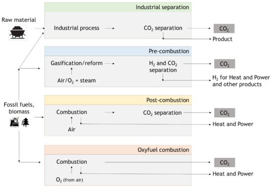
Figure 4. Scheme of methods for carbon capture (adapted from IPCC [17]).
In the production processes, namely in activities related to CO2 and other harmful greenhouse gases, even in coal power plants, it is important to reduce the emissions. For that, energy production changes as technology advances. Energy companies and industries use several technologies. This way, Industry 4.0 and the external environment force the energy companies to constantly adjust goals [18][19]. Oxy-combustion capture is still under development and is not yet commercial. Reduction of NOx, SOx, Hg emissions, and methods of exhaust gas dedusting are also important.
2.1. Pre-Combustion
In power plants, in oil, gas, and chemical industries processes, where CO2 is produced, the pre-combustion CO2 capture can be used [16]. Technologies that separate this gas from gas streams have been used for many decades. The main objective of the industries is CO2 removal to meet the required downstream product specifications, whether natural gas, hydrogen, or chemicals.
In pre-combustion CO2 capture systems, the fuel source is decarbonized before combustion. More recently, in anticipation of the requirements to limit CO2 emissions, plants design have been improved to convert the gas produced from gasification to hydrogen and CO2 and remove CO2 before the combustion of the hydrogen-rich gas in the turbine [20]. The gasification or partial oxidation process combines the reacting coal with steam and oxygen at high pressure and temperature. The product is a gaseous fuel consisting mainly of carbon monoxide and hydrogen, called synthesis gas or syngas.
After this, syngas is converted to more hydrogen and carbon dioxide by adding steam at a lower temperature. This is the Water Gas Shift Reaction (WGS) (Equation (1)). Before the combustion of the hydrogen-rich gas in the gas turbine, the CO2 is captured. The concentration can be in the range of 15–60% (dry basis/% volume), and the total pressure is typically 2–7 MPa [16][20][21]:
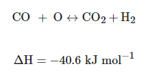 (1)
(1)When compared with post-combustion process, CO2 presents a higher concentration in the pre-combustion gas stream (>20% in the H2 + CO2 stream vs. 5–15% in a post-combustion flue gas stream). Then, CO2/H2 separation is somewhat more straightforward than the CO2/N2 separation in the post-combustion process due to the difference in molecular weights and molecular kinetic diameters [22].
CO2 and H2 can be separated using several technologies. Solvent-based CO2 capture can be applied by chemical or physical (such as the Selexol and Fluor processes) absorption of CO2 from syngas into a liquid carrier and regenerating the absorption liquid by increasing the temperature or reducing the pressure to break the absorbent-CO2 bond [23]. Sorbent, membrane, and hybrid systems that combine attributes from multiple technologies are under investigation to reduce costs and energy penalties, as well as, to improve performance [24].
2.2. Oxy-Combustion
The oxy-combustion processes were designed to remove the bulk nitrogen from the air before combustion. A combination of oxygen (95% of purity, approximately) and recycled flue gas is used for the fuel combustion. A mixture with CO2 and H2O is generated by recycling the flue gas, and this mixture is ready for sequestration without stripping of the CO2 from the gas stream [25]. The flame temperature is controlled by the amount of recycled flue gas. No chemical solvent or physical sorbent is required to separate CO2 from the flue gas due to the high concentration in the stream. The carbon dioxide rich flue gas would then be delivered by pipeline to be sequestered.
This system was developed as an alternative to the more conventional post-combustion process in coal-fired power plants. The main reason is the reduced cost of oxy-combustion when compared with post-combustion. However, although good results were obtained in laboratory scale and pilot plants, commercial plants use is still scarce [16].
2.3. Post-Combustion
Post-combustion CO2 capture systems have been used for many decades, and in this process, the CO2 is captured from the products of burning fossil fuels (coal, natural gas, or oil) or combustion exhaust gases. The flue gas passes through a liquid solvent, solid adsorbent, membrane, or another medium, depending on the method/technology, allowing the separation of the CO2 from the mixture. After that, CO2 can be transported and stored.
The drawback of post-combustion carbon capture is the low carbon dioxide concentration in the flue gases, which leads to a relatively high energy penalty and high costs of carbon capture. On the other hand, pre-combustion strives to reduce these penalties by decarbonizing the process stream before combustion, resulting in more favorable conditions and more flexible implementation, significantly reducing capture costs [26].
Several technologies can be applied for separating or capturing CO2 from a mixture of gases in an industrial process. The purification step and the technical approach used depend on the gas stream conditions, such as temperature, pressure, and concentration, and on the product purity required.
The captured and purified gas will be transported to its final destination. In the case of CCS, a pipeline is necessary to transport captured CO2 for a storage site. When CCU is applied, a spur on the pipeline can take a slipstream from the main flow to be diverted to the chemicals or synthetic fuels plant. At the end of the supply chain, a minor quantity of CO2 could still be emitted or stored [27].
2.4. Technologies for CO2 Capture
Figure 5 shows technical approaches available for CO2 separation and capture.
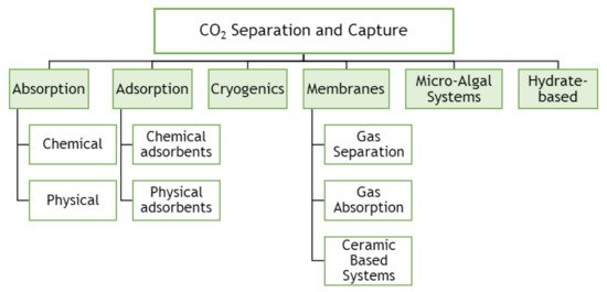
Figure 5. Technical options for CO2 capture processes (adapted from Songolzadeh, Ravanchi and Soleimani [7]).
The most common process used to separate the CO2 from natural gas, refinery off-gases, and synthesis gas processing is absorption technology [28]. This is characterized by using a liquid/solvent that selectively absorbs CO2 from a gas stream. Afterwards, the solvent can be regenerated through a stripping or regenerative process by heating and/or pressurization [29]. Absorption processes can be chemical absorption, used in pre-combustion or post-combustion capture, or physical absorption, primarily used in pre-combustion capture. Selexol (with dimethyl ethers of polyethylene glycol solvent), Rectisol (with methanol solvent), and Purisol (with N-methyl-2-pyrolidone as solvent) are the most common physical processes. Typical chemical solvents are primary amines such as monoethanolamine (MEA) and 2-amino-2-methyl-1-propanol (AMP), secondary amines such as diethanolamine (DEA), and ternary amines such as methyldiethanolamine (MDEA) [28][30]. However, in this type of process, gas streams are required at high pressure. Plants for CO2 capture with processes based on chemical absorption using MEA solvent were developed over 75 years ago to remove acidic gas impurities like H2S and CO2 from natural gas streams. Afterwards, the process was adapted to treat flue gas streams, and with this technology, about 85 to 95% of the CO2 is captured, and a product stream of CO2 can be produced with a purity higher than 99% [31].
The major challenges for CO2 capture from flue gases by absorption processes are the sizeable volumetric flow rates at atmospheric pressure with large amounts of CO2 at low partial pressures (10–15% of CO2) at 40 °C. Then, the process presents several disadvantages, which are the high energy consumption due to the high thermal energy required, around 4.0 GJ/t of CO2 captured [30] (considering 30 wt% MEA and 90% CO2 removal), the presence of SOx and NOx contaminants, and the high oxygen partial pressure, which hinders the implementation of amine absorption process [32]. Besides, it leads to corrosive product formation due to the solvents’ thermal and oxidative solvent degradation. There are many studies about processual alternatives to reduce the costs involved in power plants to reduce the operating costs. Besides the physical and chemical absorption methods discussed above, other methods could be implemented, as verified in Figure 5.
Gas separation through adsorption processes can be used in pre- and post-combustion capture and are promising alternative separation techniques characterized by solid adsorbents capable of reversibly capturing CO2. Novel adsorbent materials for CO2 capture with specific properties can adsorb large amounts of CO2 to be used or stored, being these materials instruments for CO2 utilization and storage. Adsorbents are porous solids and have a large surface area per unit mass. Each type of molecule or component creates different interactions with the adsorbent surface, leading to an eventual separation [33]. There are many types of adsorbents, which could be applied to CO2 capture by physical adsorption processes, including activated carbons, carbon fibers, zeolites [34], metal-organic frameworks [35], and organic-inorganic hybrid materials [36][37]. The adsorbent should be chosen taking into account economic and operational criteria, which are (i) high adsorption capacity for the target gas component, i.e., CO2, leading to the reduction of the adsorbent quantity and process equipment size; (ii) high CO2 selectivity, representing a high adsorption capacity ratio between CO2 and the other components in the stream, such as, nitrogen; (iii) fast adsorption and desorption kinetics; (iv) good physical and chemical stability during the cycles and regeneration steps; (v) be regenerable by modest pressure decrease or temperature increase, leading to the minimization of the operating energy costs. Furthermore, the adsorbent should ideally also have robust performance in the presence of moisture and other contaminants that may be present in the gas stream to treat. Then, there are essential features that should be considered for a successful operation of adsorbent material, such as composition, particle size, pore size, and pore connectivity.
Depending on the regeneration method, adsorption processes can be denominated as pressure swing adsorption (PSA), temperature swing adsorption (TSA), and electrical swing adsorption (ESA) [38][39].
Cryogenic carbon capture utilizes the principle of separation based on the cooling of CO2 to low temperature. The CO2 is separated from the flue gas mixture after cooling this gas below −73.3 °C at atmospheric pressure. After this, CO2 is pressurized and delivered at pipeline pressure. Cryogenic separation can be applied for post-combustion processes in two different ways. In one of these methods, CO2 can be de-sublimated to solid CO2 on the heat exchangers, further heated and pressurized to obtain liquid CO2 in the recovery stage. Clodic and Younes [40] proposed this type of separation. Tuinier et al. [41] proposed another method, with the use of packed beds for de-sublimation of CO2. CO2 is recovered from the packing material by feeding a fresh gas stream to increase the temperature and enhance the concentration of the CO2 recovered from the packed bed [42]. It may be a good technique because it does not involve any additional chemicals in the separation process. However, the high compression power requirements for this method are the major disadvantage [43].
Membranes are another potential alternative to conventional solvent absorption technology. The difference in physical and/or chemical interactions between gases and membrane materials is responsible for the CO2 separation. The method presents many advantages, such as reduced equipment size, lower energy requirements, simplicity in the process, among others. Nevertheless, in the post-combustion process, particularly in the CO2/N2 separation, due to the relatively low CO2 concentration and pressure, the driving force for membranes to perform appropriately is weak, making their implementation difficult [44].
Another potential technique for removing CO2 from flue gases is microalgae. Microalgae are microscopic organisms that typically grow suspended in water and are driven by the same photosynthetic process as higher plants [45].
Microalgal cells are sunlight-driven cell factories that can convert carbon dioxide into raw materials for producing biofuels (e.g., biohydrogen, biodiesel, and bioethanol), animal food chemical feedstocks, and high-value bioactive compounds [45].
The ability of these cells to absorb CO2 can be applied as an attractive alternative for CO2 sequestration. CO2 fixation and storage via microalgae are essentially photosynthesis, transforming water and CO2 into organic compounds without extra energy addition or consumption and secondary pollution.
Hydrate-based CO2 capture (HBCC) technology emerges as a potential solution for CO2 capture from gas streaming, e.g., fromCO2/N2 or from CO2/H2 of fossil fuel power plants. This technology is based on the hydrate cages formation by water molecules at high pressure and low temperature, where CO2 molecules stay enclathrated, allowing their separation. It is estimated that this technology could have a cost reduction of CO2 capture of about 45% when compared with the chemical absorption technology [46]. Recently, studies involving hydrate-base CO2 capture and storage have increased [47][48].
2.5. Current Progress of CCUS Facilities
Since 1972, CCS has been applied to capture CO2 from an extensive range of sectors and industries [49]. Typically, the progress of technology development contains a series of scale-up steps: first, laboratory scale or bench; second, pilot-scale; third, demonstration-scale; fourth, commercial scale. Currently, there are eighteen large-scale facilities in operation in the world, five under construction, and twenty in various stages of development [50] (see Table 1).
Table 1. Current development progress of technologies in terms of technology readiness level (TRL): carbon capture; transport; storage; and utilization (adapted from Bui [51],Consoli [50]).
| Technology Readiness Level | Current Development |
|---|---|
| TRL1 | Concept |
| TRL2 | Formulation |
 |
Ocean Storage |
| TRL3 | Proof of concept (lab tests) |
 |
Ionic Liquids-Post-combustion |
 |
BECCS Power |
 |
Low T separation-Pre-combustion |
 |
Membranes dense inorganic (CO2 separation) |
 |
Mineral storage |
| TRL4 | Lab prototype |
 |
Oxy-combustion gas turbine (water cycle) |
| TRL5 | Lab-scale plant |
 |
Membranes dense inorganic (H2 separation for reformer) |
| TRL6 | Pilot plant |
 |
Membranes polymeric (power plants) |
 |
Biphasic solvents-Post-combustion |
 |
Chemical looping combustion (CLC) |
 |
Calcium carbonate looping (CaL) |
 |
CO2 utilization (non-EOR) |
| TRL7 | Demonstration |
 |
Membranes polymeric (NG industry) |
 |
Pre-combustion IGCC + CCS |
 |
Oxy-combustion coal power plant |
 |
Adsorption-Post-combustion |
 |
BECCS industry |
 |
DAC |
 |
Depleted oil & gas fields |
 |
CO2-EGR |
| TRL8 | Commercial Refinement required |
| TRL9 | Commercial |
 |
Post-combustion amines (power plants) |
 |
Pre-combustion NG processing |
 |
Transport on-shore & off-shore pipelines |
 |
Transport ships |
 |
Saline formations |
 |
CCUS |
Notes: BECCS corresponds to bioenergy with CCS, IGCC corresponds to integrated gasification combined cycle, EGR corresponds to enhanced gas recovery, EOR corresponds to enhanced oil recovery, NG corresponds to natural gas; CO2 utilization (non-EOR) reflects a wide range of technologies, most of which have been demonstrated conceptually at the lab scale. C–Capture; T–Transport; U–Utilization; S–Storage.
2.6. Global Facilities of CCUS
More than 30 new integrated CCUS facilities have been announced since 2007, mostly in the United States and Europe, although projects are also planned in China, Australia, Korea, the Middle East and New Zealand [52]. One of them was developed by Svante [53]. Started in 2007, Svante designed and built a CO2 capture facility to capture half a tonne of carbon per day. This technology captures carbon dioxide from flue gas, concentrates it, then releases it for safe storage or industrial use, in 60 s. Today, Svante has several industrial-scale carbon capture projects and collaborations.
Another application example is Air Products. This company possesses solutions for CO₂ capture from fossil fuel conversion before it reaches the atmosphere. The technology has designed and constructed a large-scale system to capture CO₂ from steam methane reformers, which are located within the Valero Refinery in Port Arthur (TX, USA). Air Products has a technology that already separate, purify and transport CO₂ from natural gas reforming, management of syngas from gasification, and oxyfuel combustion in markets such as steel and glass [54].
The Global CCS Institute provides a database of CCUS facilities operating in the world. This organization establishes as large-scale integrated CCSU facilities in its database comprising the capture, transport, and storage of CO2 at a scale of at least 800 kt of CO2 annually for a coal-based power plant, or at least 400 kt of CO2 annually for other emission-intensive industrial facilities (natural gas-based power generation is included). The remaining facilities and initiatives in the database are mentioned as in advancement/deployment status [55]. The last update of the database refers to October 2019.
Currently, there are several CCS facilities in Europe, and they can be classified in three different classes:
- (1)
-
Commercial Carbon Capture and Storage Facilities–CO2 can be captured and transported to be permanently stored; have economic lives similar to the host facility whose CO2 is captured; must support a commercial return while operating and meet regulatory requirements;
- (2)
-
Carbon Capture and Storage Hubs–Commercial facilities although not having a full-chain (capture, transport and storage) operation; several models are considered, combining multiple capture facilities, or CO2 transport and storage;
- (3)
-
Pilot and Demonstration Facilities–CO2 is captured for testing, developing or demonstrating CCS technologies/processes; CO2 captured may or may not be transported for permanent storage; A commercial return during operation is not expected.
Taking into account this classification, actually in Europe (accessed data at 1st of April 2021), there are 13 commercial CCS Facilities, two CCS Hubs (one in The Netherlands and another one in United Kingdom), and 29 Pilot and Demonstration facilities [55]. Figure 6 shows the map of the worldwide distribution of CCUS facilities, focusing on Europe.
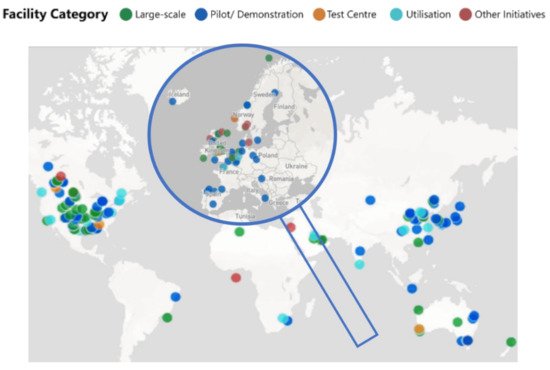
Figure 6. Worldwide distribution of CCUS facilities divided by categories, expanded in Europe (adapted from Institute [55]).
Table 2 summarises the commercial CCS facilities that are working in Europe. Other facilities are under study in test centers or the pilot or demonstration phase.
Table 2. Summary of large-scale commercial CCS facilities that are working in Europe (Notes: Status: ED—Early Development; AD—Advanced Development; O—Operational; C—Completed; In C—In Construction; Data: represents the starting year of the project; Mtpa—Million tonnes per annum; tpa—tonnens per annum; tpd—tonnes per day).
| Name | Status | Country | Data | Industry | Observations |
|---|---|---|---|---|---|
| Acorn Scalable CCS Development | ED | UK | 2020s | Oil Refining | Scale-up of the pilot project Acorn (Minimum Viable CCS Development) |
| Caledonia Clean Energy | ED | UK | 2024 | Power generation | CO2 capture would be 3 Mtpa and transported via re-purposed pipeline for geological storage in the North Sea of Scotland |
| Drax BECCS Project | ED | UK | 2027 | Power generation | Aims to capture 4 Mtpa from one (660 MW) of the biomass-fired power lines at the UK’s biggest power station by 2027 |
| Ervia Cork CCS | ED | Ireland | 2028 | Power generation and refining | CO2 captured initially from the two-modern gas-fired, combined-cycle gas turbine power stations and Ireland’s only oil refining business; transported via a pipeline network to sites in the Kinsale Gas Field |
| Hydrogen to Humber Saltend (H2H) | ED | UK | 2026–2027 | Hydrogen production | H2H Saltend is in development to produce blue hydrogen via a new build 600 MW autothermal reformer to decarbonize Triton Power’s gas-fired power plant; up to 1.4 million tonnes of CO2 will be captured. |
| Hydrogen 2 Magnum (H2M) | ED | Netherlands | 2004 | Power generation | H2M produce hydrogen to be used in gas power plant in Eemshaven, Germany, Equinor, Vattenfall and Gassunie |
| HyNet North West | ED | UK | Mid 2020s | Hydrogen Production | CO2 is planned to be captured from the Hydrogen Production & Carbon Capture plant, and transported, together with captured CO2 from existing nearby industrial sites |
| Langskip CCS–Fortum Oslo Varme | AD | Norway | 2024 | Waste Incineratiom | It is in construction to capture about 0.4 Mtpa of CO2 by 2024 from its cement production plat in southern Norway; the offshore Aurora area has been evaluated as original storage site and will involve a combined ship and pipeline transportation system. |
| Net Zero Teesside | ED | UK | 2020s | Various | Cluster of leading energy-intensive companies to examine the opportunity to build one of Europe’s first CCS equipped industrial zones in Tees Valley, UK; starts with a capture capacity of 0.8 Mtpa, that could grow up to 10 Mtpa; CO2 transported via pipeline to an offshore site in the North Sea |
| Northern Gas Network H21 North of England | AD | UK | 2026 | Hydrogen production | H21 aims to convert the UK gas grid from natural gas (methane) to zero-carbon hydrogen |
| Norway Full Chain CCS | AD | Norway | 2023–2024 | Various | Aim of 0.8 Mtpa; Capture CO2 studies are being undertaken by two proponents involved in cement production and a waste-to-energy recovery plant, both in southern Norway; CO2 would be transported via ship and pipeline to an offshore in the Smeaheia area |
| Port of Rotterdam CCUS Backbone Initiative (Porthos) | AD | Netherlands | 2023 | Various | The ambition is to store 2 Mtpa from 2023 on, a total that will run up to 5 Mtpa by 2030 |
| Sleipner CO2 Storage | O | Norway | 1996 | Natural Gas Processing | The Spleipner CO2 storage facility was the first (since 1996) in the world to inject CO2 into a dedicated geological storage (located offshore in Norway); Approximately 0.85 Mtpa is injected and over 17 Mtpa has been injected since inception to 2019 |
| Snohvit CO2 Storage | O | Norway | 2008 | Natural Gas Processing | CO2 is captured at an LNG facility on the island of Melkoya, Norway; designed to capture 0.7 Mtpa, and CO2 is transported via pipeline back to the Snohvit field offshore, where more than 4 Mtpa has been stored to date since 2008 |
| The Clean Gas Project | ED | UK | 2025 | Power generation | Natural gas will be used to generate power via a Combined Cycle Gas turbine gas-fired generation station, with CO2 captured and transported by pipeline for storage in a formation under the Southern North Sea |
As demonstrated with the set of works in development presented in Table 2, great efforts have been made to apply capture, storage, and utilization processes in plants. However, there are only a few large-scale CCS plants in operation in Europe so far. This is related to a series of obstacles preventing this technology from being adopted more widely. In most European countries, the nature of the challenges can be political, economic, technical, and social [56][57][58][59].
-
Political: lack of political commitment with CCS by some member states;
-
Economic: high investment, high operational costs, lack of competitiveness compared with other low carbon technologies; no financial compensation for the additional capital and operating costs associated with CCS; Long-term funding commitments from various public and private sources ensure the continuity of research programs which are necessary for the development of CO2 utilization;
-
Technical: lack of infrastructures for transport and storage;
-
Social: CCS is unknown for the overall public; resistance to CO2 storage concept; environmental risks concerning health and water pollution.
Efforts have been made to combat these barriers. As mentioned, to reach the targets defined in the Paris Agreement, immediate/prompt action would be required to reduce CO2 emissions. Processes related to CCS can be classified as carbon-positive, near carbon-neutral, or carbon-negative. Carbon positive corresponds to the majority of the processes, which still emit CO2 for the atmosphere. Carbon-neutral and carbon-negative emissions are responsible for zero carbon emissions (neutral) and CO2 emissions reduction to the atmosphere. Examples of the “negative” processes able to capture CO2 are Bioenergy with Carbon Capture and Storage (BECCS) and Direct Air Capture (DAC).
References
- International Energy Agency. Global Emissions in 2019. Available online: (accessed on 18 March 2021).
- International Energy Agency. Global Energy Review 2020; International Energy Agency: Paris, France, 2020; Available online: (accessed on 18 March 2021).
- Tiseo, I. Global Distribution of CO2 Emissions from Fossil Fuel and Cement by Sector 2020. Available online: (accessed on 18 March 2021).
- Climate Action Tracker. 2100 Warming Projections. Available online: (accessed on 18 April 2021).
- CarbonBrief—Clear on Climate. Explainer: The high-emissions ‘RCP8.5′ global warming scenario. Available online: (accessed on 3 September 2020).
- Pires, J.C.M.; Martins, F.G.; Alvim-Ferraz, M.C.M.; Simões, M. Recent developments on carbon capture and storage: An overview. Chem. Eng. Res. Des. 2011, 89, 1446–1460.
- Songolzadeh, M.; Ravanchi, M.T.; Soleimani, M. Carbon Dioxide Capture and Storage: A General Review on Adsorbents. World Acad. Sci. Eng. Technol. 2012, 6, 213–220.
- International Energy Agency. Carbon Capture, Utilisation and Storage. Available online: (accessed on 3 August 2020).
- Marocco Stuardi, F.; MacPherson, F.; Leclaire, J. Integrated CO2 capture and utilization: A priority research direction. Curr. Opin. Green Sustain. Chem. 2019, 16, 71–76.
- Romasheva, N.; Ilinova, A. CCS Projects: How Regulatory Framework Influences Their Deployment. Resources 2019, 8, 181.
- Global CCS Institute. The Global Status of CCS; Summary report; Global Carbon Capture and Storage Institute Ltd.: Melbourne, Australia, 2015; Available online: (accessed on 3 August 2020).
- International Energy Agency. Energy Technology Perspectives; International Energy Agency: Paris, France, 2017; Available online: (accessed on 18 March 2021).
- International Energy Agency. Transforming Industry through CCUS. 2019. Available online: (accessed on 18 March 2021).
- Dindi, A.; Quang, D.V.; Vega, L.F.; Nashef, E.; Abu-Zahra, M.R.M. Applications of fly ash for CO2 capture, utilization, and storage. J. CO2 Util. 2019, 29, 82–102.
- Olajire, A.A. CO2 capture and separation technologies for end-of-pipe applications—A review. Energy 2010, 35, 2610–2628.
- Folger, P. Carbon Capture: A Technology Assesssment; Congressional Research Service: Washington, DC, USA, 2013; p. 3.
- IPCC. IPCC Special Report on Carbon Dioxide Capture and Storage; Prepared by Working Group III of the Intergovernmental Panel on Climate Change; Metz, B.O., Davidson, H.C., de Coninck, M.L., Meyer, L.A., Eds.; Cambridge University Press: Cambridge, UK; New York, NY, USA, 2005; p. 442.
- Borowski, P.F. Nexus between water, energy, food and climate change as challenges facing the modern global, European and Polish economy. AIMS Geosci. 2020, 6, 397–421.
- Nota, G.; Nota, F.D.; Peluso, D.; Toro Lazo, A. Energy Efficiency in Industry 4.0: The Case of Batch Production Processes. Sustainability 2020, 12, 6631.
- Global CCS Institute. CO2 Capture Technologies; Global Carbon Capture and Storage Institute: Canberra, Australia, 2012; pp. 1–13.
- Pastor-Pérez, L.; Baibars, F.; Le Sache, E.; Arellano-García, H.; Gu, S.; Reina, T.R. CO2 valorisation via Reverse Water-Gas Shift reaction using advanced Cs doped Fe-Cu/Al2O3 catalysts. J. CO2 Util. 2017, 21, 423–428.
- Rackley, S.A. Carbon Capture from Power Generation, 2nd ed.; Carbon Capture and Storage; Elsevier: London, UK, 2017; ISBN 9780128120415.
- U.S. Department Energy. Pre-Combustion CO2 Capture. Available online: (accessed on 15 August 2020).
- National Energy Technology Laboratory Post-Combustion CO2 Capture. Available online: (accessed on 1 April 2021).
- Buhre, B.J.P.; Elliott, L.K.; Sheng, C.D.; Gupta, R.P.; Wall, T.F. Oxy-fuel combustion technology for coal-fired power generation. Prog. Energy Combust. Sci. 2005, 31, 283–307.
- Wong, S. Module 3—CO2 Capture: Pre-Combustion (Decarbonisation) and Oxy-Fuel Technologies; Global CCS Institute: Docklands, VIC, Australia, 2011; Volume 1, pp. 45–54. Available online: (accessed on 3 August 2020).
- Armstrong, K.; Styring, P. Assessing the Potential of Utilization and Storage Strategies for Post-Combustion CO2 Emissions Reduction. Front. Energy Res. 2015, 3.
- Bhown, A.S.; Freeman, B.C. Analysis and Status of Post-Combustion Carbon Dioxide Capture Technologies. Environ. Sci. Technol. 2011, 45, 8624–8632.
- Leung, D.Y.C.; Caramanna, G.; Maroto-Valer, M.M. An overview of current status of carbon dioxide capture and storage technologies. Renew. Sustain. Energy Rev. 2014, 39, 426–443.
- Luis, P. Use of monoethanolamine (MEA) for CO2 capture in a global scenario: Consequences and alternatives. Desalination 2016, 380, 93–99.
- Walspurger, S.; Van Dijk, H.A.J. EDGAR CO2 Purity: Type and Quantities of Impurities Related to CO2 Point Source and Capture Technology: A Literature Study; The Energy Research Centre of The Netherlands: Petten, The Netherlands, 2012.
- Samanta, A.; Zhao, A.; Shimizu, G.K.H.; Sarkar, P.; Gupta, R. Post-Combustion CO2 Capture Using Solid Sorbents: A Review. Ind. Eng. Chem. Res. 2012, 51, 1438–1463.
- Grande, C.A. Advances in Pressure Swing Adsorption for Gas Separation. ISRN Chem. Eng. 2012, 2012, 13.
- Regufe, M.J.; Ribeiro, A.M.; Ferreira, A.F.P.; Rodrigues, A. CO2 Storage on Zeolites and Other Adsorbents. In Nanoporous Materials for Gas Storage; Kaneko, K., Rodríguez-Reinoso, F., Eds.; Springer: Singapore, 2019; pp. 359–381.
- Yang, H.; Li, J.-R. Metal-Organic Frameworks (MOFs) for CO2 Capture. In Porous Materials for Carbon Dioxide Capture; Lu, A.-H., Dai, S., Eds.; Springer: Berlin/Heidelberg, Germany, 2014; pp. 79–113.
- Regufe, M.J.; Tamajon, J.; Ribeiro, A.M.; Ferreira, A.; Lee, U.H.; Hwang, Y.K.; Chang, J.-S.; Serre, C.; Loureiro, J.M.; Rodrigues, A.E. Syngas Purification by Porous Amino-Functionalized Titanium Terephthalate MIL-125. Energy Fuels 2015, 29, 4654–4664.
- Lu, C.; Bai, H.; Wu, B.; Su, F.; Hwang, J.F. Comparative study of CO2 capture by carbon nanotubes, activated carbons, and zeolites. Energy Fuels 2008, 22, 3050–3056.
- Regufe, M.J.; Ferreira, A.F.P.; Loureiro, J.M.; Rodrigues, A.; Ribeiro, A.M. Development of Hybrid Materials with Activated Carbon and Zeolite 13X for CO2 Capture from Flue Gases by Electric Swing Adsorption. Ind. Eng. Chem. Res. 2020, 59, 12197–12211.
- Regufe, M.J.; Ferreira, A.F.P.; Loureiro, J.M.; Rodrigues, A.; Ribeiro, A.M. Electrical conductive 3D-printed monolith adsorbent for CO2 capture. Microporous Mesoporous Mater. 2019, 278, 403–413.
- Clodic, D.; Younes, M. A new Method for CO2 Capture: Frosting CO2 at Atmospheric Pressure. In Proceedings of the Greenhouse Gas Control Technologies—6th International Conference, Kyoto, Japan, 1–4 October 2002; Gale, J., Kaya, Y., Eds.; Pergamon: Oxford, UK, 2003; pp. 155–160.
- Tuinier, M.J.; van Sint Annaland, M.; Kramer, G.J.; Kuipers, J.A.M. Cryogenic CO2 capture using dynamically operated packed beds. Chem. Eng. Sci. 2010, 65, 114–119.
- Nanda, S.; Reddy, S.N.; Mitra, S.K.; Kozinski, J.A. The progressive routes for carbon capture and sequestration. Energy Sci. Eng. 2016, 4, 99–122.
- Hart, A.; Gnanendran, N. Cryogenic CO2 capture in natural gas. Energy Procedia 2009, 1, 697–706.
- Kenarsari, S.D.; Yang, D.; Jiang, G.; Zhang, S.; Wang, J.; Russell, A.G.; Wei, Q.; Fan, M. Review of recent advances in carbon dioxide separation and capture. RSC Adv. 2013, 3, 22739–22773.
- Klinthong, W.; Yang, Y.-H.; Huang, C.-H.; Tan, C.-S. A Review: Microalgae and Their Applications in CO2 Capture and Renewable Energy. Aerosol Air Qual. Res. 2015, 15, 712–742.
- Yang, M.; Song, Y.; Jiang, L.; Zhao, Y.; Ruan, X.; Zhang, Y.; Wang, S. Hydrate-based technology for CO2 capture from fossil fuel power plants. Appl. Energy 2014, 116, 26–40.
- Zheng, J.; Chong, Z.R.; Qureshi, M.F.; Linga, P. Carbon Dioxide Sequestration via Gas Hydrates: A Potential Pathway toward Decarbonization. Energy Fuels 2020.
- Matsuo, S.; Umeda, H.; Takeya, S.; Fujita, T.A. Feasibility Study on Hydrate-Based Technology for Transporting CO2 from Industrial to Agricultural Areas. Energies 2017, 10, 728.
- Quadrelli, R.; Peterson, S. The energy-climate challenge: Recent trends in CO2 emissions from fuel combustion. Energy Policy 2007, 35, 5938–5952.
- Consoli, C. Bioenergy and Carbon Capture and Storage; Global CCS Institute: Docklands, Australia, 2019.
- Bui, M.; Adjiman, C.S.; Bardow, A.; Anthony, E.J.; Boston, A.; Brown, S.; Fennell, P.S.; Fuss, S.; Galindo, A.; Hackett, L.A.; et al. Carbon capture and storage (CCS): The way forward. Energy Environ. Sci. 2018, 11, 1062–1176.
- International Energy Agency, CCUS in Clean Energy Transitions. Available online: (accessed on 18 March 2021).
- Svante. Capturing Carbon Economically, Today. Available online: (accessed on 18 March 2021).
- Air Products. Carbon Capture. Available online: (accessed on 18 March 2021).
- Global CCS Institute. Facilities Database. Available online: (accessed on 4 August 2020).
- Townsend, A.; Gillespie, A. Scalling Up the CCS Market to Deliver Net-Zero Emissions; Global CCS Institute: Docklands, Australia, 2020; Available online: (accessed on 18 March 2021).
- Budinis, S.; Krevor, S.; Dowell, N.M.; Brandon, N.; Hawkes, A. An assessment of CCS costs, barriers and potential. Energy Strategy Rev. 2018, 22, 61–81.
- Karayannis, V.; Charalampides, G.; Lakioti, E. Socio-economic Aspects of CCS Technologies. Procedia Econ. Financ. 2014, 14, 295–302.
- Stigson, P.; Hansson, A.; Lind, M. Obstacles for CCS deployment: An analysis of discrepancies of perceptions. Mitig. Adapt. Strateg. Glob. Chang. 2012, 17, 601–619.


