 +1 credit
| Version | Summary | Created by | Modification | Content Size | Created at | Operation |
|---|---|---|---|---|---|---|
| 1 | Mandeep Kaur | + 8436 word(s) | 8436 | 2021-01-12 08:10:40 |
Video Upload Options
Endoscopes are used routinely in modern medicine for in-vivo imaging of luminal organs. Technical advances in the micro-electro-mechanical system (MEMS) and optical fields have enabled the further miniaturization of endoscopes, resulting in the ability to image previously inaccessible small-caliber luminal organs, enabling the early detection of lesions and other abnormalities in these tissues. A large number of optical devices have been researched and developed for imaging purposes. Among these, optical coherence tomography (OCT), confocal microscopy (CM), and photoacoustic (PA) imaging are the predominant ones. The size of an endoscope is highly dependent on the actuation and scanning method used to illuminate the target image area. Different actuation methods used in the design of small-sized cantilever-based endoscopes are reviewed in here along with their working principles, advantages and disadvantages, generated scanning patterns, and applications.
1. Introduction
The use of optical devices in medical applications has increased in the last few decades. The main purpose of optical imaging techniques is the direct localization of lesions and malignancies in the organs to inform and assist with surgical procedures.
Most of the preliminary endoscopes were developed using coherent optical fiber bundles (CFBs) to transport light from a light source to the imaged surface and using charge-coupled devices (CCDs) to image the tissue surface [1]. Those CCD devices contained approximately 200,000 pixels, which provided limited resolution of the image [2]. The image resolution and optical magnification in newly developed endoscopes was enhanced using complementary metal oxide semiconductor (CMOS) chips, which provided images with over 1.3 MPixels of diffraction-limited resolution [3]. However, a minimum center-to-center distance between the optical fibers in a CFB and the honeycomb effect produced by the non-imaging area between fibers still limited the resolution in devices having a diameter smaller than 3 mm, independently of the imaging chip used [4].
Recently developed flexible endoscopes scan the laser light at the proximal end and capture the image on a temporal basis, i.e., acquiring one pixel at a time. In such devices, the tip displacement of an optical fiber acting as a cantilever beam dictates the field of view (FOV) and the resolution of the obtained image. Scanning and actuation techniques used to excite a cantilever beam play a critical role in the performance of such a scanning device. In the current review, the mathematical models and applications of MEMS actuators in fiber optic cantilever-based scanners are reported to provide information about the underlying working physics of these devices and can provide a foundation for the development of miniaturized and more efficient MEMS scanners.
2. Cantilever Beam Mechanics
In small cantilevered optical scanners, the image is obtained by scanning the light beam at the distal end of the device, as stated earlier. In most of the earlier endoscopes using CFBs to transport the light to the tissue surface, the beam is scanned using micromirrors placed at the proximal end of the device. In these so-called proximal scanners, the large-dimensioned scanning components can be separated from the distal end of the endoscopic device. Thus, it is possible to fabricate very compact-sized scanning devices. However, as the beam sweeps light across the CFB, a portion of the light enters through the cladding of the fibers as well, which results in poor contrast in the image. On the other hand, the scanning device is placed at the distal end of an endoscopic scanner to illuminate the light on the target sample in distal scanners. These single-fiber-based endoscopes require distal scanning to sweep the light across the target sample [5]. Among the distal scanners, it is possible to have forward-viewing or side-viewing configurations of devices based on the scanning direction [6].
The cantilever-based endoscopic scanners belong to the category of forward-view imaging devices. In such devices, an optical fiber is fixed at a distance of a few millimeters from its distal end. The free end of the fiber acts as a cantilever beam, which can either be vibrated at resonance, or at a frequency different from their resonant frequency.
2.1 Resonant scanners
The main advantage of using the driving frequency equal to the resonant frequency consists in obtaining a higher tip displacement of the free end of the fiber, which results in high-resolution images (higher number of pixels in the FOV).
Almost all the cantilevered-fiber optic endoscopes can be considered as cylindrical-shaped beams. The first resonant frequency (also called natural frequency) of a cylindrical-shaped cantilevered beam (where one side is rigidly blocked for any movement and the other end is free to move) is given by:

with E, ρ, R, and L being the Young’s modulus, density, radius, and length of the cantilever beam, respectively [7]. From this equation, the driving frequency in resonant scanners depends on the inherent properties and dimensions of the optical fiber acting as the cantilever beam.
The deflection of a cantilevered beam in the transverse direction can be obtained considering the Euler–Bernoulli beam. The Euler–Bernoulli beam theory describes the relationship between the beam deflection w(x,t) and the applied load f(x,t), assuming small deformations in the beam such that the planes perpendicular to the x-y axis do not bend after the deformation. The equation describing the deflection w(x,t) of the beam in the y direction, in time (t) and along the length (x), can be derived considering the force and moment equilibrium of an infinitesimal element dx of the beam as in Figure 1. For uniform cross-section cantilever beams, it results in:

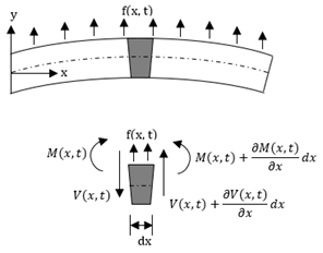
Figure 1. Euler–Bernoulli beam and a free body diagram of an element of the beam.
The beam deflection can be solved using equation (2) with four boundary conditions and two initial conditions. The initial conditions are the specified initial deflection and velocity profiles causing the motion:

For a cantilever beam, the boundary conditions are the zero bending moment and the shear force at the free end, and no deflection and slope at the fixed end. In other words,


Equation (3) can be solved by separating variables as in w(x,t) = X(x)T(t). This approach permits the separation of Equation (3) into two sub-equations, which can be solved separately to yield temporal and spatial results. The total solution can be obtained by combining the two results. As stated above, the temporal solution depends upon the initial conditions, which vary from case to case. Given the boundary conditions, the spatial part yields:

where 


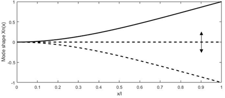
Figure 2. Deformation of a cantilever beam at resonance.
Depending upon the actuation technique used to excite the cantilever beam, it is possible to observe the development of 2D motion of the fiber tip by exciting the fiber along one direction. The so-called whirling motion, causing the fiber tip to follow an elliptical-shaped pattern instead of its linear motion, is caused by the cross-coupling of the motion between the planes perpendicular to the beam axes. It is possible to obtain a stable whirling motion within a small frequency range [8][9]. The cross-coupling motion can be avoided by exciting the cantilever beam along certain eigendirections [10]. It is even seen that the whirling effect can be positively exploited for 2-D scanning using a single actuator. Wu et al. developed a fiber optic scanner able to obtain 2D scanning using nonlinear cross-couplings [11].
2.2 Non-resonant scanners
Some actuation methods are unable to generate motion at very high frequency. It is difficult to generate resonant scanners characterized with a low resonant frequency as they require long and slender beams, compromising their mechanical stability. In addition, the fiber tip displacement occurs symmetrically to the optical axis and is difficult to offset in resonant scanners. In such cases, the cantilevered optical fibers are excited at a frequency different from their resonant frequency.
In such scanners, the deflection of the distal tip of the fiber 


with L, a, q, E, I, g being the length of the cantilevered portion of the fiber, length ratio of the fixed end, mass per unit length of the fiber, Young’s modulus, the moment of the inertia of the fiber, and acceleration of the gravity, respectively [12].
Zhang et al. proposed a similar scanner where a 45-mm-long fiber was electrothermally actuated using a micro-electro-mechanical (MEMS) actuator operating at no more than 6 V [12]. A similar scanner was developed by Park et al., where a 40-mm-long fiber, used as an endoscopic OCT probe, was actuated using a 3 V power source [13]. Some researchers were able to develop cantilevered scanners working at a frequency not too far from their resonance frequency. In such semi-resonant scanners, the fiber tip provided an intermediate displacement, and no nonlinear whirling effects were present. Moon et al. developed an OCT probe where the cantilever scanner was excited at 63 Hz using a piezo-tube actuator [14].
3. Actuators in Cantilever-Based Endoscopic Devices
The miniature size of MEMS devices, along with their light weight and stable performance characteristics, makes them attractive for micro and nano applications, among which are endoscopic optical devices. On the basis of the working principle, MEMS actuators can be subdivided into piezoelectric, electrostatic, electrothermal, electromagnetic, and shape memory alloy actuators. The piezoelectric actuators are widely used in endoscopic catheter design due to their compact size, low power consumption, and large output force. On the other hand, the actuation displacement is limited in such devices. Electrostatic actuators are the second most used actuation method in medical scanning devices due to their fast response and ease of fabrication. However, it is difficult to produce such devices at very small dimensions, which limits their use in systems requiring a distal actuation. Electrothermal actuators generate high actuation displacement and force, but the elevated working temperature and low working frequency limit their use in some cases. Electromagnetic and shape memory alloy actuators find limited applications in cantilevered fiber optic endoscopic scanners [15]. All these actuation methods are described in this section in great detail and compared in Table 1, where the number of ticks qualitatively indicates the intensity of a certain pattern [6].
Table 1. Comparison between different actuation methods used in cantilevered endoscopes.
|
|
Electrostatic |
Electro-Thermal |
Piezoelectric |
Electromagnetic |
Shape Memory Alloy |
|
Force |
✓ |
✓ |
✓✓✓ |
✓✓ |
✓✓✓ |
|
Displacement amplitude |
✓✓ |
✓✓✓ |
✓ |
✓✓✓ |
✓✓ |
|
Compactness |
✓✓✓ |
✓✓✓ |
✓✓ |
✓ |
✓✓ |
|
Power consumption |
✓✓ |
✓ |
✓ |
✓✓✓ |
✓✓✓ |
|
Working principle |
Electrostatic force |
Thermal expansion |
Piezoelectric effect |
Magnetization effect |
Material deformation |
|
Motion range |
1D/2D |
1D/2D |
2D |
1D |
1D |
|
Scanning pattern |
Spiral |
Lissajous |
Spiral |
Linear |
Linear |
|
Advantages |
Fast response, low voltage required, easy fabrication, and no hysteresis |
Large displacement, low operating voltage, small dimensions |
Large force generated, wide operating frequency range, low power consumption |
Large displacement obtained, quick and linear response, easy to control |
Flexibility, large frequency response |
|
Disadvantages |
Large device dimensions, pull-in problem, complicated circuit |
High working temperature, not operable at very high frequencies |
Limited displacement |
Large device dimensions, difficult to manufacture |
Low displacement |
3.1. Piezoelectric Actuators
The working principle of piezoelectric actuators is based on the so-called piezoelectric effect. Piezoelectric materials have the ability to change the material polarization in the presence of a mechanical stress and conversely generate strain or force in the presence of an external electric field. Among the various crystalline, ceramic, and polymeric materials, aluminum nitride (AlN) and lead zirconate titanate (PZT) are most frequently used in MEMS devices. Piezoelectric actuators are characterized by providing fast response, low driving voltage, and low power consumption [16].
The relationship between the electric field applied to the material and the mechanical deformation exhibited by the material is nonlinear due to the presence of hysteresis and drift. For a small variation in electric field, the material behavior is almost linear and can be described by:

where ε is the strain tensor, E is the electric field vector, σ is the stress tensor, d is the piezoelectric tensor (vector of strain coefficients), and c is the elastic tensor. In the case of no external force, the second component on the right-hand side of Equation (10) becomes zero. The piezoelectric strain depends upon the direction of the mechanical and electrical fields.
Normally, piezoelectric devices are restricted for 1D operation with force/displacement occurring along the axis defined by the electric field. In these so-called longitudinally translating piezo chips, the electric field is applied parallel to the polarization direction of the material, which causes the displacement in the same direction of the field normal to the surface of the electrodes. In shear piezo elements, the polarization is obtained in the direction perpendicular to the field direction. Thus, there is an orthogonal relationship between the direction of the displacement and that of the electric field [17].
Piezoelectric actuators are available in single disc/plate and tubular configurations. These configurations are described below in detail.
3.1.1. Disc Piezoelectric Actuator
Flat disc piezoelectric actuators can be constructed using a single piezo element (unimorph actuators) or using two different piezo elements (bimorph actuators). In either case, piezo elements are connected to a base material. There is an expansion or contraction of the piezo material in the presence of an electric current, which provides the bending motion of the actuator. The schematic diagram showing the working principle of a piezo bending actuator is shown in Figure 3. When a positive voltage is applied to the piezoelectric ceramic layer, it elongates in x direction, while the base material does not change its length, resulting in convex bending of actuator towards the conductive layer, as in Figure 3b. Similarly, bending in the opposite direction occurs by applying a negative voltage to the piezoelectric sheet. Li et al. fabricated a scanning fiber probe for an OCT endoscope, where an optical fiber was placed in the middle of the two piezoelectric plates with a common copper substrate element. The bending of the fiber tip in the vertical direction was obtained by exciting the two piezo elements with the same voltage, i.e., the structure will bend along the positive or negative directions by elongating or contracting both elements. On the other side, the motion of the tip along the horizontal axis was obtained by applying an opposite polarity voltage to the two elements. A two-dimensional Lissajous scanning pattern was obtained by the fiber tip by controlling the voltages on the two layers [18].
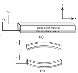
Figure 3. Piezoelectric bending actuator: (a) schematic diagram; (b) working principle.
Tekpinar et al. developed a piezoelectric fiber scanner where two planar piezo bimorph cantilever actuators were placed perpendicular to each other to generate the 2D motion of an optical fiber connected to them. In this case, the dimensions of the cantilevered fiber and the mode optimization allowed the fiber tip to interchangeably follow a raster, spiral, or Lissajous scanning pattern by simply changing the actuation parameters [19]. Rivera et al. developed a compact multiphoton endoscope (with an outer diameter of 3 mm) where two bimorph piezoelectric actuators were used to excite a DCF. Two bimorph structures were placed in such a configuration to have perpendicular bending axes. A raster scanning pattern was generated by exciting the fiber in two directions [20].
3.1.2. Tubular Piezoelectric Actuator
In the tubular structure, a thin ceramic sheet is bent into a cylindrical shape and can experience axial, radial, or bending motion. The tube shrinks radially and axially in the presence of a voltage difference between the inner and outer electrodes of the tube. In these actuators, the load can be mounted either on the curved surface for radial displacement or on the rims for axial displacement. These devices are very rapidly responsive, but the generated force is limited. Usually, the displacement produced by a piezoelectric device is very small. Thus, it is possible to stack up various piezoelectric disks or tubes to amplify the generated displacement.
As described earlier, piezoelectric actuators are most commonly used in cantilever-based endoscopic probes, especially the tubular piezoelectric actuators. In this case, the tube structure is divided into four electrodes and placed near the blocked end of the cantilever fiber. The base excitation of the fiber along a certain direction is obtained by applying voltage to two opposite electrodes. Seibel et al. used this configuration to obtain a 2D displacement of the fiber tip. In this small-sized endoscope, the drive voltage at two pairs of electrodes had an increasing amplitude and a phase shift of 90°, which resulted in a spiral pattern followed by the fiber tip [21]. The schematic diagram of the scanning fiber endoscope is shown in Figure 4 along with an enlarged view of the scanning portion showing the cantilevered fiber’s connection with the tubular actuator [4].
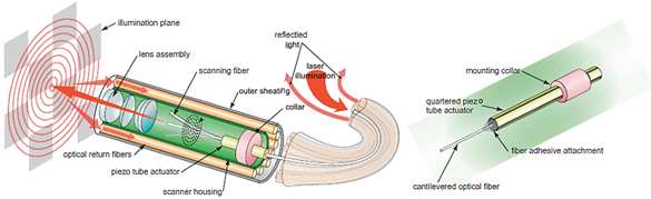
Figure 4. Schematic diagram of a scanning fiber endoscope (taken with permission of [4]).
A similar fiber optic scanner using a tubular piezoelectric actuator, packaged within a 2 mm housing tube, was developed by Liang et al. as a two-photon and second harmonic endoscope. This novel endo-microscope enabled label-free histological imaging of tissue structures with subcellular resolution [22]. Vilches et al. developed a fiber scanner for OCT where a piezoelectric tubular actuator provided the base excitation motion to an optical fiber having a GRIN lens attached to its free end [23].
3.2. Electrothermal Actuators
The working principle of an electrothermal actuator is based on the Joule effect. The electric resistivity causes an increase in temperature in the presence of the current flow through the actuator. The amount of heat generated in a material is directly proportional to the material’s resistivity, current, and the length of the actuator, while it is inversely proportional to the cross-sectional area of the device. Generated heat causes thermal expansion and consequently the deformation of the material.
In electrothermal actuators, the cross-section is usually much smaller than the length of the actuator to make it more resistive and, consequently, cause higher temperature variations for a given input power. Thus, the temperature along the actuator can be calculated using a one-dimensional model. A correction factor can be included in the equation to consider this approximation. The nonlinear partial differential equation describing the temperature variation (T) in space and time can be obtained using the conservation of energy [24]. In the case of a rectangular section bar (with width w, and height h), the partial differential equation (PDE) describing the heat transfer along the length x becomes:

with ρ, cp, ρr, kp being the density, specific heat, resistivity, and the thermal conductivity of the material characterizing the actuator, respectively. hcs and hcf are the convection coefficients for the side walls and the faces of the actuator element, respectively. λ is the coefficient describing the heat loss. εx and σ are the surface emissivity and the Stefan–Boltzmann constant for radiation heat transfer, respectively, while Tp and Ta are the substrate and ambient temperature, respectively. RT is the thermal resistance between the actuator surface and the substrate material. J is the current density along the actuator given by the current passing through it per unit section of the actuator material. S is the shape factor and is a function of total heat flux defined as:

where tv is the air gap between the actuator material and the substrate [24][25].
The heat transfer through convection and radiation is evident at very high temperatures. In electrothermal actuators, the operable temperature is limited to avoid damage to the material. Thus, Equation (11) can be simplified to [24][26] :

The temperature profile along the actuator can be determined knowing the initial temperature of the actuator and the two boundary conditions.
On the basis of configuration, electrothermal actuators can be divided into hot-and-cold arm, chevron, and bimorph actuators.
3.2.1. Hot-and-Cold Arm Actuators
These actuators are also called U-shaped actuators, folded beam actuators, heatuators, or pseudo bimorph actuators. As the name implies, the structure of the actuator is made up of at least one hot arm and one cold arm. The actuator is usually made up of a homogenous material with folded arms in a U-shaped pattern that are constrained by anchors. Usually, the anchor surfaces are characterized by having a large surface area, required to ensure heat dissipation. Two arms of the actuator characterized by different cross-sections are connected in series to an electric circuit. The current flows through the structure with different current densities within the two arms. Therefore, more heat is produced within the thin arm through the Joule heating principle compared to that of the wide arm. This differential thermal expansion of the material causes the thin arm to expand more and bend towards the wide section, generating the bending moment [15][27].
At the base of the cold arm, there is a thin section flexure arm which helps the bending deflection at the tip of the actuator in the shape of an arc in the actuator plane. The length of the flexure arm plays an important role in the value of the tip deflection. In the original model proposed by Guckel at al., the length of the flexure arm and the wide arm were equal to half of the length of the thin arm [28]. Huang and Lee developed the mathematical model describing the tip displacement of the actuator tip with respect to the function of the air gap between the two arms and the geometry of the arm structures. The smaller gap between the two arms led to a higher tip displacement, and the optimal length for the flexure arm was around 14–18% of the total length of the thin arm [29].
The temperature along the beam can be obtained by unfolding the beam and applying Equation (13). In the case of no external load acting on the tip, the lateral deflection of the tip at the free end of these actuators can be described by:

where L, a, A, r, α, I are the actuator length, ratio of flexure arm length to hot arm length, cross-section area of the flexure and hot arm, center gap between the hot arm and the flexure component, coefficient of thermal expansion, and the moment of inertia of the hot arm (flexure arm), respectively. ΔTnet is the net temperature difference defined as the temperature which would cause the expansion of the hot arm alone and is the same as the net expansion in the real actuator case, where a small expansion of the cold arm corresponds to a decrease in the flexure component and results in a decrease in the net expansion between the two arms [30].
Hot-and-cold arm actuators are used widely in MEMS devices. There are large variations in the geometry of the actuators to achieve asymmetric thermal expansion. It is possible to obtain the in- plane deflection by changing the length of the arms instead of the cross-section [31], or using a combination of both the difference in the length and cross-section [32], or connecting the two arms of the actuator in parallel instead of series, enabling higher current density in the thick arm, causing the tip deflection towards the thin arm [33], or changing the resistivity of one arm by selectively doping it.
Lara-Castro et al. designed an array of four electrothermal actuators based on the hot-and-cold arm configuration to obtain out-of-plane displacement. Four actuators are used to control the rotation of a MEMS mirror for endoscopic OCT purposes [34]. Some other changes in the geometry of the actuator include using two hot arms [35]. Seo et al. used this kind of double hot arm electrothermal actuator to obtain the lateral in-plane displacement of the optical fiber for endoscopic purposes, where an optical fiber was firmly connected to the linking bridge connecting the two hot arms and the cold arm. The differential thermal expansion between hot and cold arms allowed the cantilevered fiber to move in a lateral direction (in-plane motion), while that between the actuator surface and the fiber gave the vertical motion, causing the fiber tip to follow a Lissajous scanning pattern [36].
3.2.2. Chevron Actuators
Chevron actuators are also called bent-beam actuators or V-shaped actuators and are the other type of in-plane electrothermal actuator, with a slightly different working principle. In this case, the in-plane displacement of the tip of the actuator is obtained from the total thermal expansion of the components instead of a differential expansion [15].
In a V-shaped electrothermal actuator, two symmetrical slanted beams are connected at a certain angle to a central shuttle beam at the apex to the base with anchors. The current passing through the actuator causes the thermal expansion of both slanted beams due to the Joule heating principle. As the movement of the beam is constrained by the anchors and the central shuttle, the thermal expansion causes a compression force and a bending moment, which gives rise to the lateral displacement of the shuttle beam [37].
Similar to the U-shaped beams, the temperature distribution along the arms of the actuator can be obtained using Equation (13). Enikov et al. described the analytical model for V-shaped thermal actuators. The analysis of the beam deformation was considered by taking into account the buckling effect in the beam due to the axial thermal load and transversely applied force, if any. The numerical solution of the thermoelastic buckling model of the beam led to the tip deflection of the beam or the central shuttle beam [37]. However, Sinclair presented a simplified model describing the tip displacement to be:

where θ is the initial tilt angle of the arm beam, l is the length of the single actuator arm, and l’ is the elongation due to thermal expansion [38].
These actuators provide certain advantages over the bent-beam actuators described earlier, such as rectilinear displacement, larger exhibited force at the tip, and lower power consumption [15]. The displacement of the central tip of the actuator can be increased by using longer arm components or reducing the bending angle θ. The opposite changes increase the exhibited force. Moreover, it is possible to amplify the motion of the shuttle beam by connecting the two bent-beam actuators in cascade. In the cascaded configuration, two V-shaped electrothermal actuators are anchored to the substrate and connected together with secondary V-shaped beams. The current can be passed either through the primary units only or through all the structural components [39]. Similarly, it is possible to increase the output force without changing the displacement from the device by placing multiple V-shaped actuators in parallel [38]. It is even possible to combine the parallel and cascade configurations to obtain the desired displacement and force outputs [40].
Another variation in chevron actuators consists of changing the geometry of the actuator to obtain a wide range of output properties. Among these, the most frequently used are the electrothermal actuators with Z-shaped patterned arms. In this configuration, the thermal expansion of the beams is blocked due to symmetry constraints, leading to the bending of the beams and thus the in-plane displacement of the central shuttle element. Z-shaped actuators permit smaller feature sizes and larger displacement compared to the V-shaped electrothermal actuators [15][41]. Another alternative in chevron actuators is a combination of straight and bent beams, or the so-called kink actuator. This kind of actuator consists primarily of straight arms which undergo thermal expansion by the Joule effect, while the small kink in the middle serves to guide the motion of the actuator. Kink actuators provide higher displacement at lower power levels as compared to V-shaped actuators [42].
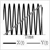
Chevron actuators find use in some cantilever-based optical scanners. Kaur et al. developed a sub-millimeter-sized cantilevered fiber optical scanner that can find use as a forward-viewing endoscopic probe. In this design, shown in Figure 5a, an electrothermal chevron actuator made with two parallel legs excites an SMF at resonance. In this case, the total thermal expansion of the actuating material provides a base excitation motion to the cantilevered fiber [43]. A resolution target image captured with this scanner is provided in Figure 5b.
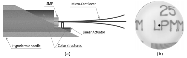
Figure 5. Cantilevered fiber scanner using chevron actuator: (a) schematic diagram; (b) reconstructed image of a resolution target.
3.2.3. Bimorph Actuators
A third class of electrothermal MEMS actuators is bimorph or bi-material type actuators. In this kind of actuator, two or more materials with different thermal expansion coefficients are stacked on top of each other. The different thermal expansion causes the actuator to bend or curl due to the induced strain generated by the Joule heating during actuation, which results in an out-of-plane motion [27].
The basic design of a bimorph electrothermal actuator consists of a cantilever-shaped micro-actuator fabricated using two layers of different materials connected to each other. The bending direction of the actuator tip during actuation will be dictated by the material with the higher thermal expansion coefficient compared to the one with the lower thermal expansion coefficient. The mathematical model for the tip deflection of such a micro-actuator is described by Chu et al. [44]. Assuming a constant curvature, the deflection at the free end of a cantilevered bi-material actuator is given by:

with L being the length of the cantilevered bi-metallic beam, and k being the curvature, which is:

where r is the radius of curvature, b, t, E, α are the width, thickness, Young’s modulus of elasticity, and the thermal expansion coefficient, respectively, of the two materials characterizing the actuator. ΔT is the change in temperature due to Joule heating [44].
As with other electrothermal actuators, it is possible to place the different bimorph actuators in a cascaded configuration to amplify the obtainable tip displacement. In such structures, the various bimorphs are placed together in a serpentine direction, which causes the tip deflection from each bimorph to be added in series, yielding the higher overall tip displacement. It is possible to use different geometries for the bimorph structures to adapt according to the required spacing limitations in the microdevices. Large numbers of bimorph structures can be connected in a vertical cascaded form to generate a large out-of-plane displacement. Many bimorph structures can also be placed in parallel to lift the high load mirror surface [45].
Bimorph actuators are the most frequently used electrothermal actuators and find use in a large number of scanning mirror MEMS devices. Zhang et al. developed a cantilevered fiber scanner excited non-resonantly using a MEMS stage. This platform, placed at a certain distance from the fixed end of the fiber, was connected to the fixed surface using three-segment bimorph actuators at four edges. Three segments of the Al-SiO2 bimorph actuators were placed in a configuration to cancel out the lateral motion generating large vertical motion at the fiber tip [12]. Such a device along with imaging optics was packaged in a 5.5 mm probe to use as an endoscopic OCT probe [13].
3.3. Electromagnetic Actuators
The working principle that governs the motion in these actuators is the so-called electromagnetic principle, where the conversion from electric/magnetic energy to mechanical energy takes place by means of a magnetic field. Similar to an electrostatic actuator, there are stationary and moving parts, named the stator and the rotor, respectively. Depending on whether the magnetic field is generated by the static or rotor component, there are two different configurations available for these actuators. Both configurations are described below in detail.
3.3.1. Moving Magnet Configuration
In this configuration of MEMS electromagnetic actuators, a bulk magnet is placed inside an electric coil. When the current flows inside the wire coil, it generates a magnetic field. The intensity of the generated magnetic field depends upon the current passing through the coil, the radius of the coil surface, and the distance from the coil. For a circular coil, the generated magnetic field is given by the Biot–Savart equation:

where µ0 is the permeability constant, N is the number of turns, I is the current, r is the mean radius, and z is the distance along central axis [46].
In the moving magnet configuration, a permanent magnet with net magnetization vector 


with Vmag being the magnetic volume. Using a soft magnetic material, the generated torque TH rotates M moving it away from the equilibrium position (easy axis) by an angle θ. An anisotropy magnetic torque Ta will be generated inside the magnet, tending to realign it to its initial position. An opposite torque Ta is exerted on the easy axis and thus on the magnet itself. In equilibrium, the field torque TH rotates M from easy axis and is balanced by the anisotropy torque Ta and tends to align M and vibrate the magnetic component [47].
Joos et al. developed an OCT probe for imaging based on this technique. In this probe, an electromagnetic coil was placed at the outer surface in the center, in which a magnet was placed carrying a thin-walled 28-gauge tube. An SMF fiber was contained in a “S”-shaped 34-gauge stainless-steel tube placed within the 28-gauge tube. In the presence of an electric current at the coil, the electromagnetic force generated the sliding motion of the 28-gauge tube along the curved part of the inner S-shaped tube, allowing the fiber to move in the lateral direction [48].
Sun et al. developed a cantilevered fiber scanner for medical endoscopic applications, where an SMF with a collimating lens was excited at resonance using an electromagnetic actuator working on this principle. The researchers fixed a soft cylindrical magnet to an optical fiber using a 1 mm diameter polyimide pipe, and a tilted coil was fabricated using a microfabrication lithography technique. In the presence of an AC current applied to the coil, a magnetic field was generated within the coil and vibrated the magnet fixed to the fiber, resulting in excitation of the fiber [49]. Two tilted coils can be used to drive the fiber in two directions to obtain a 2D image [50].
A similar probe was recently developed by Yao et al., where a cantilevered fiber containing a mass element and a lens at its tip was excited at a second resonance mode using a pair of flexible driving coils. The geometry of the cantilevered portion generated a 2D elliptical motion, with a larger scan angle at the fiber tip in the presence of a magnetic force generated by the soft magnet in the presence of a magnetic field [51].
3.3.2. Moving Coil Configuration
In the moving coil configuration, an electric coil is fabricated on the scanner and is placed inside a static magnetic field created by external magnets. When the current flows through the coil in the presence of an external magnetic field, a force is exerted on the coil, designated as the Lorentz force. The force generated on the coil is given by:

where 

with rn being the distance of the nth coil turn from the center [53].
As in the previous case, the actuator (coil surface) deforms due to the generated torque, and a restorative torque will arise in the coil to bring it to its initial state, causing the vibration of the moving coil. This technique is frequently used to actuate micromirror surfaces [54][55] and finds limited use in cantilevered fiber scanners.
3.3.3. Magnetostrictive Actuation
Magnetic materials are characterized by a special property which allows them to change their dimensions in the presence of a magnetic field. This effect is called magnetostriction. The material can undergo a change in dimension until it reaches the value of saturation magnetostriction, which depends on the magnetization and, therefore, on the applied magnetic field [56].
Bourouina et al. developed a 2D optical scanner based on the magnetostrictive effect. In this case, a silicon cantilever was coated with a magnetostrictive film. Due to the uniaxial nature of the magnetostrictive material, bending and torsion vibrations were generated simultaneously in the presence of an AC magnetic field generated by the electric coils placed in its surroundings. Later, a piezoresistive detector was incorporated in the device to measure the bending and torsional vibrations [57].
A slightly different fiber optic scanner was developed by a group of researchers from the University of Texas. In this design, an optical fiber was coated with a ferromagnetic gel which experienced a bending motion in the presence of an external magnetic field generated by a magnet placed at the outer surface [58].
3.4. Electrostatic Actuators
An electrostatic actuator includes at least two pairs of electrodes attached to two plates separated by a gap. One of these plates is fixed by anchors and is named the stator, while the other plate is able to move and is designated the shuttle. In the presence of a voltage difference between the two plates, an attractive electrostatic force generates among them, causing the movement of the shuttle plate towards the stator. The amount of the electrostatic force generated between the two components depends on the gap and the dielectric constant of the media separating the two plates. The generated electrostatic force is given by:

where A is the electrode area, ε is the dielectric constant of the air, V is the total voltage difference applied to the plates, and g is the air-gap distance [59]. The maximum voltage that can be applied to a pair of electrostatic electrodes is delimited by the pull-in voltage. The electrostatic force increases with the applied voltage until the point when the force causes the two plates to collapse together. The maximum applicable voltage without causing this phenomenon is called pull-in point voltage. The electrostatic actuators can be classified into parallel plate and comb drive, which are described below.
3.4.1. Parallel Plate Actuator
In a parallel plate configuration, two electrodes are placed parallel to each other in an interdigitated finger configuration. In optical scanners, the moving electrode is mostly represented by a polysilicon mirror used to deflect the light.
Another variation of a parallel plate actuator is a system where the moving electrode has a rotational degree of freedom. The application of the voltage to the electrodes in this case causes the rotation of the moving electrode with a tilt angle obtained from the equilibrium between the electrostatic torque generated by the electrostatic force and the restoring torque. The large deflection angle in this case requires a large air gap between the electrodes. The maximum deflection of the rotating electrode should be less than one third of the air gap to avoid the pull-in phenomenon [60].
Most of the torsional electrostatic actuators are divided into small-sized scanner arrays causing large tilting angles with small air gaps. There are some systems developed with tapered electrodes to allow large tilting angles.
One of the main drawbacks of electrostatic actuators is that a large driving voltage is required to obtain moderate deflection angles. It is possible to partially overcome this by using tapered electrodes instead of the parallel-shaped ones [61].
3.4.2. Comb Drive Actuator
In electrostatic comb actuators, multiple plates are connected to make interdigitated static and mobile rows. Such a configuration enables an increase in the interaction area between the two electrodes, and, consequently, high electrostatic forces are generated. As in the parallel plate configuration, the out-of-plane motion of the mobile mirror structure can be obtained by making a vertical offset between the torsional support and the driving arm [60].
In vertical comb drives, the moving comb motion is out-of-plane with the motion of the fixed comb, which avoids the pull-in phenomenon. Moreover, the deflecting mirror can be decoupled from the actuating part, permitting a large possible deflection of the mirror itself. The higher electrostatic torque generated by the comb structure leads to the possibility of higher driving frequencies and thus a higher scan speed [62].
Vertical comb drives are used frequently to actuate micromirrors [63][64][65]. It is possible to place the moving comb structures at a certain angle with respect to the fixed ones to obtain an angular vertical comb drive. The initial angle between the comb structures determines the obtainable maximum angle rotation of the mirror connected to it [66].
A group of researchers at Fraunhofer University studied the design optimization for comb drive micro-actuators. It was more convenient to place the electrodes in a star-shaped pattern to obtain a higher deflection of the mirror surface [67].
Both types of actuators are mainly used to actuate micromirrors [16]. Munce et al. developed an electrostatically driven fiber optic scanner where a single-mode fiber was placed in a platinum coil. The packaged probe had a diameter of 2.2 mm. There were two insulated wires placed around the optical fiber which acted as electrodes. An electrostatic force was generated around the fiber in the presence of a potential difference between the two electrodes, which allowed the fiber tip to vibrate [68].
4. Scanning Patterns
In MEMS scanning mirrors or fiber optic scanners, the laser beam is scanned along two perpendicular axes to reconstruct the image of the target sample. The scan along the two directions can be implemented either using separate actuation methods or by a single actuation device. The resolution of the image obtained depends upon the scanning method used to scan the laser beam across the sample [64]. The different scanning methods used by the optical scanners are briefly reported below.
4.1. Raster Scanning
Raster scanning (also called serpentine scanning) is a commonly used scanning pattern. In this case, the scanning image is subdivided into scan lines in one direction. The beam sweeps the sample in one direction along a line, comes back to other side, and again starts scanning along the next line. Thus, it follows a rectangular scan pattern. The axis of the line scan is called the fast axis (scanned rapidly), while the other axis is called the slow axis (scanned slowly). Usually, the fast axis is driven by oscillating the light beam at resonance, while the slow-axis scan is performed using a non-resonant scan [64]. Typically, the raster scan pattern is obtained using gimbal-mounted micromirrors or optical fiber scanners. The raster scanners require high operating voltages to get slow-axis scans and have difficulties incorporating them in small spaces, which make them less usable in clinical devices [69].
4.2. Spiral Scanning
A spiral scan pattern is generated using a 2-D actuation method by employing the same actuation frequency along two axes. In other words, the spiral pattern is obtained by driving the light beam at the same frequency with increasing amplitude along two directions with a phase shift of 90° [69].
The phase shift between the two signals, and the amplitude variation in the driving signal affect the circularity of the obtained spiral. Such scanning patterns are obtained with resonant fiber-optic scanner. These scanners are activated with increasing actuation amplitude until they reach the maximum radius (rmax) followed by a breaking time to reset the fiber to its rest position, which then repeats the scan and moves to the next frame [4].
4.3. Lissajous Scanning
A Lissajous scanning pattern is another 2-D scanning pattern obtained with variable frequencies, and phases along two axes. One of the main parameters characterizing the scanning pattern is its fill factor, defined as the ratio of the scanned area vs. the total pixel area in the image. The fill factor depends on the ratio of the frequencies along the two axes. For a higher fill factor, a high ratio between the two scanning frequencies is desired [53]. The scanning pattern is quasi-random and non-repetitive in time. The scanning beam is uniformly spread on the scanned surface, is highly smooth, and requires low power consumption [70]. Such patterns are not very useful for high quality displays; however, they are largely used in resonant fiber scanners [71][72].
4.4. Circular Scanning
A circular section optical fiber is characterized by having the same fundamental frequency along two directions. It is possible to get a circular-shaped pattern from the fiber tip by exciting it in the two directions with a 90° phase shift [19]. As stated earlier, it is also possible to get a circular-shaped pattern from the fiber tip by exciting it in a single direction at a second mode of resonance due to nonlinear coupling with longitudinal inertia [73].
By changing the amplitude of the driving signal, it is possible to sweep the area inside the circular shape like the spiral shape pattern. Wu et al. developed an imaging fiber optic catheter, where the 2-D scan is obtained using a concentric circle scan pattern with the help of a triangle amplitude modulated sinusoidal actuation wave [73]. Like the spiral-shaped pattern, the light density is higher in the center and decreases moving toward the outer circle.
4.5. Propeller Scanning
Propeller scanning consists of generating a line scan by actuating the optical fiber in one direction, or steering the beam using a mirror device. The line pattern is then rotated to generate a circular-shaped 2-D pattern [74]. The rotation motion can be transmitted from the proximal end to the distal end using torque cables, while the optical connection between the steady and rotating parts can be applied using fiber optic rotary joints.
The line scan direction represents the fast axis, while the rotation represents the slow axis. The light intensity is not uniform and is higher in the center compared to the edges. The rotation speed affects the resolution of the obtained image. Kaur et al. used a propeller scanning pattern to get a 2-D scan pattern using a single direction actuation of a cantilevered fiber. The fast-axis scan is obtained by using an electrothermal actuator, while the slow-axis scan is performed by rotating the target sample [43].
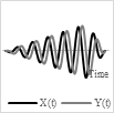
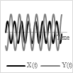
Scanning patterns and the actuation power provided to the two actuators to get the corresponding 2-D pattern are shown in Table 2 along with their advantages and disadvantages.
Table 2. Comparison table for different scanning patterns.
|
|
Raster |
Spiral |
Lissajous |
Circular |
Propeller |
|
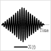
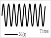
Scanning pattern |
|
|
|
|
|
|
Actuation pattern |
|
|
|
|
Y(t) constant rotation |
|
Advantages |
Uniform light intensity |
Easy to get, area is swept by changing the driving voltage |
Uniform light intensity, most used |
Possible to get circular pattern with 1D actuation, area is swept by changing the driving voltage |
Easy to generate |
|
Disadvantages |
Points are scanned at different times can lead to motion artifacts |
Light intensity is higher in center |
Fill factor highly depends on the frequency ratio, quasi-random pattern |
Light intensity is higher in center |
Non uniform light intensity, the rotation of miniaturized structure requires complex and expensive devices |


5. Discussion
Optical endoscopic imaging enabled the visualization of cellular and subcellular structures in real time, enabling early interventions and improved diagnostic yield from fewer biopsies. Moreover, the less invasive nature of the imaging device results in reduced tissue trauma, low risk of complications and operational costs, and fast recovery times. In cantilever fiber endoscopes, an optical fiber is rigidly fixed to an actuator’s substrate surface, leaving a few millimeters of free end at its distal end. Most often, this free end is vibrated at resonance to obtain a large tip displacement, which in these imaging devices is directly related to the resolution of the obtained image. Various imaging applications, such as confocal endo-microscopy, OCT, photoacoustic imaging, etc., can be found using such endoscopes.
Frequently used MEMS actuators in fiber optic endoscopic devices comprise piezoelectric, electrothermal, electromagnetic, electrostatic, and shape memory alloy actuators. Piezoelectric actuators are available in plate or tubular structure, among which the latter is largely used as it provides the base excitation to the fiber held in the center along two directions. By linearly increasing the amplitude of sinusoidal voltages at two pairs of electrodes with a 180° phase shift, one can obtain a spiral scanning pattern.
Electrothermal actuators are available in three different types including hot-and-cold arm, chevron, and bimorph actuators. In a hot-and-cold arm actuator, the different geometries of the two legs produce asymmetric heat generation and, consequently, an asymmetric thermal expansion, generating a bending motion at the actuator tip. Similarly, in bimorph actuators, the different material properties cause the bending of the actuator tip. These techniques can be combined with other actuation methods to obtain a 2D Lissajous scanning pattern. Chevron actuators have symmetrical legs and provide linear 1D motion at the tip.
Electrostatic actuators are available in parallel plate and comb drive configurations. These actuators find limited use in fiberoptic scanners due to their large dimensions but are frequently used in scanners having proximal scanning devices such as mirrors.
The shape recovery property of shape memory alloy materials makes them an excellent alternative for providing a large actuation force in compact dimensions.
Various imaging endoscopic devices using these actuators are described in this paper. The performance of some recently developed fiber optic cantilever-based scanners is summarized and compared with the clinically available endoscopes in Table 3.
Table 3. Fiber-optic cantilevered scanners developed for endomicroscopy.
|
Actuation Principle |
Imaging Modality |
Scanning Direction |
Resolution |
FOV |
Frequency |
Driving Voltage |
Frame Rate |
Scanner Dimensions |
Scanning Pattern |
Cantilever Fiber |
|
Piezoelectric bimorph |
Multiphoton |
Forward |
0.8 µm (lateral), 10 µm (axial) |
110 µm x 110 µm |
1.05 kHz (fast axis), 4.1 Hz |
50 Vpp (resonant bimorph) 200 Vpp (non-resonant) |
4.1 fps (512 x 512 pixels) |
3 mm (diameter) 40 mm (rigid length) |
Raster scan |
DCF |
|
Piezoelectric tube |
Two-photon |
Forward |
0.61 µm ÷ 1.10 µm (from center of FOV to peripheric zone) |
160 µm |
3.1 kHz |
48 Vpp |
6 fps |
~2 mm (diameter) |
Spiral |
DCF with GRIN lens |
|
Piezoelectric tube |
Two-Photon |
Forward |
10 µm |
70° |
5 kHz |
25 V |
15 fps |
1.6 mm (diameter) |
Spiral |
SMF |
|
Piezoelectric thin film |
E-OCT |
Side-view |
5 µm (axial) |
152° |
394 Hz |
1.3 Vpp |
- |
3.4 mm x 2.5 mm |
radial |
- |
|
Electrothermal |
Confocal endomicroscope |
Forward |
~1.7 µm |
378 µm x 439 µm |
239 Hz (x-axis) 207 Hz (y-axis) |
16 Vpp |
1 fps |
1.65 mm (diameter) 28 mm (rigid length) |
Lissajous |
SMF |
|
Electrothermal |
OCT (A-scan) |
Forward |
~17 µm (lateral) ~9 µm (axial) |
~3 mm (beam scanning) |
~100 Hz |
3 Vac_pp, 1.5 V DC offset |
200 fps |
5.5 mm (diameter) 55 mm (rigid length) |
raster |
- |
|
Electromagnetic |
OCT (B-scan) |
Forward |
4–6 µm (axial) 25–35 µm (lateral) |
2 mm |
5 Hz |
±10 V (triangle wave) |
- |
0.51 mm (diameter) |
Linear |
SMF |
|
Micromotor |
PA and US endoscopy |
Side-view |
~58 µm (PA radial) ~30 µm (US radial) ~100 µm (PA transvers) ~120 µm (US transverse) |
~310° |
~4 Hz |
~3.2V DC |
4 fps |
2.5 mm (diameter) ~35 mm (Rigid length) |
Radial |
MMF |
|
Electromagnetic |
Confocal |
Forward |
0.8 µm (lateral) |
390 um x 390 um |
700 Hz (fast scan) 1–2 Hz (slow scan) |
- |
1 fps |
8 mm (diameter) |
Raster |
SMF |
|
Cellvizio |
Confocal |
Forward |
5–15 µm (axial) 2–5 µm (lateral) |
600 µm x 500 µm |
- |
- |
12 fps |
2.5 mm |
- |
- |
As stated earlier, scanning fiber endoscopes were introduced recently in the field. Most of the devices mentioned in this paper find limited use in clinical application but are more in the transition from research to clinical phase. The only commercially available cantilever-based endoscopes for clinical use are those developed by Pentax and Mauna Kea Technologies.
The choice of an endoscopic device depends on the target imaging region, ease of use, and cost of the device. The cost of an endoscopic device comprises fabrication and operating cost. The operating costs mainly consist in decontamination and sterilization, which can be performed at high temperature such as autoclaving or hot air oven or at low temperature using chemical agents. The fabrication cost of an endoscope highly depends on the cost of the laser source, actuation, and detection mechanisms. Among the various actuators studied in this paper, electrothermal actuators are economic ones. However, the high working temperature can limit their usage at a high frequency. Otherwise, piezoelectric tubular actuators are cost-effective in terms of possible bidirectional actuation at high actuation frequency. The development of MEMS actuators enabled batch production of miniaturized actuators, reducing the fabrication costs to great extent and permitting the fabrication of disposable endoscopic scanners.
The article is from 10.3390/s21010251
References
- Joshua Anthony Udovich; Nathaniel D. Kirkpatrick; Angelique Kano; Anthony Tanbakuchi; Urs Utzinger; Arthur F. Gmitro; Spectral background and transmission characteristics of fiber optic imaging bundles. Applied Optics 2008, 47, 4560-4568, 10.1364/ao.47.004560.
- Jayan Mannath; Matthew R. Banks; Emerging technologies in endoscopic imaging. F1000 Medicine Reports 2012, 4, 3, 10.3410/m4-3.
- Endoscopes Use CMOS Image Sensors . Vision Systems Design. Retrieved 2021-1-12
- Cameron M. Lee; Christoph J. Engelbrecht; Timothy D. Soper; Fritjof Helmchen; Eric J. Seibel; Scanning fiber endoscopy with highly flexible, 1 mm catheterscopes for wide-field, full-color imaging. Journal of Biophotonics 2010, 3, 385-407, 10.1002/jbio.200900087.
- Benjamin A Flusberg; Eric D Cocker; Wibool Piyawattanametha; Juergen C Jung; Eunice L M Cheung; Mark J Schnitzer; Fiber-optic fluorescence imaging. Nature Methods 2005, 2, 941-950, 10.1038/nmeth820.
- Mandeep Kaur; Pierre M. Lane; Carlo Menon; Endoscopic Optical Imaging Technologies and Devices for Medical Purposes: State of the Art. Applied Sciences 2020, 10, 6865, 10.3390/app10196865.
- Inman, D.J.. Engineering Vibrations; Horton, M.J.; Dias, N.; Disanno, S., Eds.; CRC Press: Pearson: NJ, USA, 2014; pp. 502-572.
- E. C. Haight; W. W. King; Stability of Nonlinear Oscillations of an Elastic Rod. The Journal of the Acoustical Society of America 1972, 52, 899-911, 10.1121/1.1913195.
- Michael W. Hyer; Whirling of a base‐excited cantilever beam. The Journal of the Acoustical Society of America 1979, 65, 931-939, 10.1121/1.382597.
- Matthew J. Kundrat; Per G. Reinhall; Cameron M. Lee; Eric J. Seibel; High performance open loop control of scanning with a small cylindrical cantilever beam. Journal of Sound and Vibration 2011, 330, 1762-1771, 10.1016/j.jsv.2010.10.019.
- Ling Wu; Zhihua Ding; Gang Huang; Realization of 2D scanning pattern of a fiber cantilever by nonlinear coupling. SPIE Proceedings 2007, 1, 65340I-65340I-8, 10.1117/12.741140.
- Xiaoyang Zhang; Can Duan; Lin Liu; Xingde Li; Huikai Xie; A non-resonant fiber scanner based on an electrothermally-actuated MEMS stage. Sensors and Actuators A: Physical 2015, 233, 239-245, 10.1016/j.sna.2015.07.001.
- Hyeon-Cheol Park; Xiaoyang Zhang; Wu Yuan; Liang Zhou; Huikai Xie; Xingde Li; Ultralow-voltage electrothermal MEMS based fiber-optic scanning probe for forward-viewing endoscopic OCT. Optics Letters 2019, 44, 2232-2235, 10.1364/ol.44.002232.
- Sucbei Moon; Sang-Won Lee; Marc Rubinstein; Brian J. F. Wong; Zhongping Chen; Semi-resonant operation of a fiber-cantilever piezotube scanner for stable optical coherence tomography endoscope imaging. Optics Express 2010, 18, 21183-21197, 10.1364/oe.18.021183.
- Sijie Yang; Qingsong Xu; A review on actuation and sensing techniques for MEMS-based microgrippers. Journal of Micro-Bio Robotics 2017, 13, 1-14, 10.1007/s12213-017-0098-2.
- Eakkachai Pengwang; Kanty Rabenorosoa; Micky Rakotondrabe; Nicolas Andreff; Scanning Micromirror Platform Based on MEMS Technology for Medical Application. Micromachines 2016, 7, 24, 10.3390/mi7020024.
- Piezoelectric Tutorial . Thorlabs. Retrieved 2021-1-12
- Guangping Li; Ai Zhou; He Gao; Zhihai Liu; Endoscope two dimensional scanning fiber probe and the driving method. International Conference on Optical Instruments and Technology (OIT2011) 2011, 8199, 819913-819913, 10.1117/12.905054.
- Miyase Tekpınar; Ramin Khayatzadeh; Onur Ferhanoğlu; Multiple-pattern generating piezoelectric fiber scanner toward endoscopic applications. Optical Engineering 2019, 58, 023101, 10.1117/1.oe.58.2.023101.
- David R. Rivera; Christopher M. Brown; Dimitre G. Ouzounov; Ina Pavlova; Demirhan Kobat; Watt W. Webb; Chris Xu; Compact and flexible raster scanning multiphoton endoscope capable of imaging unstained tissue. Proceedings of the National Academy of Sciences 2011, 108, 17598-17603, 10.1073/pnas.1114746108.
- R. Ubbink; Louisa Jd Van Dijk; Desirée Van Noord; Tanja Johannes; Patricia A C Specht; Marco J. Bruno; Egbert G. Mik; Evaluation of endoscopic visible light spectroscopy: comparison with microvascular oxygen tension measurements in a porcine model. Journal of Translational Medicine 2019, 17, 65, 10.1186/s12967-019-1802-x.
- Wenxuan Liang; Gunnsteinn Hall; Bernhard Messerschmidt; Ming-Jun Li; Xingde Li; Nonlinear optical endomicroscopy for label-free functional histology in vivo. Light: Science & Applications 2017, 6, e17082-e17082, 10.1038/lsa.2017.82.
- Sergio Vilches; Simon Kretschmer; Çağlar Ataman; Hans Zappe; Miniaturized Fourier-plane fiber scanner for OCT endoscopy. Journal of Micromechanics and Microengineering 2017, 27, 105015, 10.1088/1361-6439/aa8915.
- Mohammad Mayyas; Comprehensive Thermal Modeling of ElectroThermoElastic Microstructures. Actuators 2012, 1, 21-35, 10.3390/act1010021.
- Liwei Lin; Mu Chiao; Electrothermal responses of lineshape microstructures. Sensors and Actuators A: Physical 1996, 55, 35-41, 10.1016/s0924-4247(96)01247-2.
- Hongyun So; Albert P. Pisano; Electrothermal modeling, fabrication and analysis of low-power consumption thermal actuator with buckling arm. Microsystem Technologies 2013, 21, 195-202, 10.1007/s00542-013-1953-2.
- R.A. Buser; N.F. De Rooij; H. Tischhauser; A. Dommann; G. Staufert; Biaxial scanning mirror activated by bimorph structures for medical applications. Sensors and Actuators A: Physical 1992, 31, 29-34, 10.1016/0924-4247(92)80076-f.
- H. Guckel; J. Klein; T. Christenson; K. Skrobis; M. Laudon; E.G. Lovell; Thermo-magnetic metal flexure actuators. Technical Digest IEEE Solid-State Sensor and Actuator Workshop 1992, 1, 73-75, 10.1109/solsen.1992.228273.
- Qing-An Huang; Neville Ka Shek Lee; Analysis and design of polysilicon thermal flexure actuator. Journal of Micromechanics and Microengineering 1998, 9, 64-70, 10.1088/0960-1317/9/1/308.
- Ryan Hickey; Marek Kujath; Ted Hubbard; Heat transfer analysis and optimization of two-beam microelectromechanical thermal actuators. Journal of Vacuum Science & Technology A 2002, 20, 971-974, 10.1116/1.1468654.
- Q.-A. Huang; N. K. S. Lee; Analytical modeling and optimization for a laterally-driven polysilicon thermal actuator. Microsystem Technologies 1999, 5, 133-137, 10.1007/s005420050152.
- C.-C. Lee; Wensyang Hsu; Optimization of an electro-thermally and laterally driven microactuator. Microsystem Technologies 2003, 9, 331-334, 10.1007/s00542-002-0253-z.
- Timothy Moulton; G.K Ananthasuresh; Micromechanical devices with embedded electro-thermal-compliant actuation. Sensors and Actuators A: Physical 2001, 90, 38-48, 10.1016/s0924-4247(00)00563-x.
- Miguel Lara-Castro; Adrian Herrera-Amaya; Marco A. Escarola-Rosas; Moisés Vázquez-Toledo; Francisco López-Huerta; Luz Antonio Aguilera-Cortés; Agustin Herrera-May; Design and Modeling of Polysilicon Electrothermal Actuators for a MEMS Mirror with Low Power Consumption. Micromachines 2017, 8, 203, 10.3390/mi8070203.
- Roberto Venditti; Jacky S H Lee; Yu Sun; Dongqing Li; An in-plane, bi-directional electrothermal MEMS actuator. Journal of Micromechanics and Microengineering 2006, 16, 2067-2070, 10.1088/0960-1317/16/10/020.
- Yeong-Hyeon Seo; Hyeon-Cheol Park; Ki-Hun Jeong; Electrothermal MEMS fiber scanner with lissajous patterns for endomicroscopic applications. 2016 IEEE 29th International Conference on Micro Electro Mechanical Systems (MEMS) 2015, 24, 367-370, 10.1109/memsys.2016.7421637.
- E.T. Enikov; S.S. Kedar; K.V. Lazarov; Analytical model for analysis and design of V-shaped thermal microactuators. Journal of Microelectromechanical Systems 2005, 14, 788-798, 10.1109/jmems.2005.845449.
- M.J. Sinclair; A high force low area MEMS thermal actuator. ITHERM 2000. The Seventh Intersociety Conference on Thermal and Thermomechanical Phenomena in Electronic Systems (Cat. No.00CH37069) 2002, 1, 127-132, 10.1109/itherm.2000.866818.
- Long Que; Jae-Sung Park; Y.B. Gianchandani; Bent-beam electrothermal actuators-Part I: Single beam and cascaded devices. Journal of Microelectromechanical Systems 2001, 10, 247-254, 10.1109/84.925771.
- Sohail Iqbal; Afzaal A. Malik; Rana I. Shakoor; Design and analysis of novel micro displacement amplification mechanism actuated by chevron shaped thermal actuators. Microsystem Technologies 2018, 25, 861-875, 10.1007/s00542-018-4078-9.
- Changhong Guan; Yong Zhu; An electrothermal microactuator with Z-shaped beams. Journal of Micromechanics and Microengineering 2010, 20, 1-9, 10.1088/0960-1317/20/8/085014.
- Ehab Rawashdeh; Ayman Karam; Ian G. Foulds; Characterization of Kink Actuators as Compared to Traditional Chevron Shaped Bent-Beam Electrothermal Actuators. Micromachines 2012, 3, 542-549, 10.3390/mi3030542.
- Mandeep Kaur; Malcolm Brown; Pierre M. Lane; Carlo Menon; An Electro-Thermally Actuated Micro-Cantilever-Based Fiber Optic Scanner. IEEE Sensors Journal 2020, 20, 9877-9885, 10.1109/jsen.2020.2992371.
- Wen-Hwa Chu; M. Mehregany; R L Mullen; Analysis of tip deflection and force of a bimetallic cantilever microactuator. Journal of Micromechanics and Microengineering 1993, 3, 4-7, 10.1088/0960-1317/3/1/002.
- Quentin A. A. Tanguy; Sylwester Bargiel; Huikai Xie; Nicolas Passilly; Magali Barthès; Olivier Gaiffe; Jaroslaw Rutkowski; Philippe Lutz; Christophe Gorecki; Design and Fabrication of a 2-Axis Electrothermal MEMS Micro-Scanner for Optical Coherence Tomography. Micromachines 2017, 8, 146, 10.3390/mi8050146.
- Roer Eka Pawinanto; Jumril Yunas; Burhanuddin Majlis; Azrul Hamzah; Design and Fabrication of Compact MEMS Electromagnetic Micro-Actuator with Planar Micro-Coil Based on PCB. TELKOMNIKA (Telecommunication Computing Electronics and Control) 2016, 14, 856-866, 10.12928/telkomnika.v14i3.3998.
- Jack W. Judy; Richard S. Muller; Magnetically actuated, addressable microstructures. Journal of Microelectromechanical Systems 1996, 6, 249-256, 10.1109/84.623114.
- Karen M. Joos; Jin-Hui Shen; Miniature real-time intraoperative forward-imaging optical coherence tomography probe. Biomedical Optics Express 2013, 4, 1342-1350, 10.1364/boe.4.001342.
- Bin Sun; Renshi Sawada; Zhuoqing Yang; Yi Zhang; Toshihiro Itoh; Ryutaro Maeda; Design and fabrication of driving microcoil with large tilt-angle for medical scanner application. 2014 Symposium on Design, Test, Integration and Packaging of MEMS/MOEMS (DTIP) 2014, -, 1-6, 10.1109/dtip.2014.7056688.
- Bin Sun; Hirfoumi Nogami; Yao Pen; Renshi Sawada; Microelectromagnetic actuator based on a 3D printing process for fiber scanner application. Journal of Micromechanics and Microengineering 2015, 25, 075014, 10.1088/0960-1317/25/7/075014.
- Jinyuan Yao; Zhuoqing Yang; Tao Peng; Bin Sun; Haodong Zhang; Mengyuan Zhao; Bo Dai; Hua Liu; Guifu Ding; Renshi Sawada; et al. A Single-Fiber Endoscope Scanner Probe Utilizing Two-Degrees-of-Freedom (2DOF) High-Order Resonance to Realize Larger Scanning Angle. IEEE Transactions on Components, Packaging and Manufacturing Technology 2019, 9, 2332-2340, 10.1109/tcpmt.2019.2951102.
- Xingdong Lv; Weiwei Wei; Xu Mao; Yu Chen; Jinling Yang; Fuhua Yang; A novel MEMS electromagnetic actuator with large displacement. Sensors and Actuators A: Physical 2014, 221, 22-28, 10.1016/j.sna.2014.10.028.
- Sven T. S. Holmstrom; Utku Baran; Hakan Urey; MEMS Laser Scanners: A Review. Journal of Microelectromechanical Systems 2014, 23, 259-275, 10.1109/jmems.2013.2295470.
- Pedro R. Barbaroto; Luiz Otavio S Ferreira; Ioshiaki Doi; Micromachined scanner actuated by electromagnetic induction. Optomechatronic Systems III 2002, 4902, 691-698, 10.1117/12.467641.
- Tsung-Lin Tang; Chia-Pao Hsu; Wen-Chien Chen; Weileun Fang; Design and implementation of a torque-enhancement 2-axis magnetostatic SOI optical scanner. Journal of Micromechanics and Microengineering 2010, 20, 025020, 10.1088/0960-1317/20/2/025020.
- B. D. Cullity; C. D. Graham; Magnetostriction and the Effects of Stress. Introduction to Magnetic Materials 2009, -, 241-273, 10.1002/9780470386323.ch8.
- Tarik Bourouina; Eric Lebrasseur; Gilbert Reyne; Alexis Debray; Hiroyuki Fujita; Alfred Ludwig; Eckhard Quandt; Hideo Muro; Takahiko Oki; Akira Asaoka; et al. Integration of two degree-of-freedom magnetostrictive actuation and piezoresistive detection: application to a two-dimensional optical scanner. Journal of Microelectromechanical Systems 2002, 11, 355-361, 10.1109/jmems.2002.800561.
- Praveen Pandojirao-Sunkojirao; Smitha Rao; Pratibha C. Phuyal; Naresh Dhaubanjar; J.-C. Chiao; A Magnetic Actuator for Fiber-Optic Applications. International Journal of Optomechatronics 2009, 3, 215-232, 10.1080/15599610903174440.
- Collard, D.; Fujita, H.; Toshiyoshi, B.; Legrand, B.; Buchaillot, L. . Microsystems Technology: Fabrication, Test & Reliability; Boussey, J., Eds.; Kogan Page Science: London, UK, 2003; pp. 75-115.
- Bourouina, T.; Fujita, H.; Reyne, G.; Motamedi, M.E.; MOEMS: Micro-Opto-Electro-Mechanical Systems. MOEMS: Micro-Opto-Electro-Mechanical Systems 2005, -, 323-367, 10.1117/3.2265061.
- Henri Camon; F. Larnaudie; Fabrication, simulation and experiment of a rotating electrostatic silicon mirror with large angular deflection. Proceedings IEEE Thirteenth Annual International Conference on Micro Electro Mechanical Systems (Cat. No.00CH36308) 2000, -, 645-650, 10.1109/memsys.2000.838594.
- Pamela Rae Patterson; Dooyoung Hah; Makoto Fujino; Wibool Piyawattanametha; Ming C. Wu; Scanning micromirrors: an overview. Optics East 2004, 5604, 195-208, 10.1117/12.582849.
- Wibool Piyawattanametha; Robert P. J. Barretto; Tony H. Ko; Benjamin A. Flusberg; Eric D. Cocker; Hyejun Ra; Daesung Lee; Olav Solgaard; Mark J. Schnitzer; Fast-scanning two-photon fluorescence imaging based on a microelectromechanical systems two- dimensional scanning mirror. Optics Letters 2006, 31, 2018-2020, 10.1364/ol.31.002018.
- Ulrich Hofmann; Joachim Janes; Hans-Joachim Quenzer; High-Q MEMS Resonators for Laser Beam Scanning Displays. Micromachines 2012, 3, 509-528, 10.3390/mi3020509.
- Takashi Izawa; Takashi Sasaki; Kazuhiro Hane; Scanning Micro-Mirror with an Electrostatic Spring for Compensation of Hard-Spring Nonlinearity. Micromachines 2017, 8, 240, 10.3390/mi8080240.
- Aaron D. Aguirre; Paul R. Hertz; Yu Chen; James G. Fujimoto; Wibool Piyawattanametha; Li Fan; Ming C. Wu; Two-axis MEMS Scanning Catheter for Ultrahigh Resolution Three-dimensional and En Face Imaging. Optics Express 2006, 15, 2445-2453, 10.1364/oe.15.002445.
- Harald Schenk; Peter Dürr; Detlef Kunze; Hubert Lakner; Heinz Kück; A resonantly excited 2D-micro-scanning-mirror with large deflection. Sensors and Actuators A: Physical 2001, 89, 104-111, 10.1016/s0924-4247(00)00529-x.
- Nigel R. Munce; Adrian Mariampillai; Beau A. Standish; Mihaela Pop; Kevan J. Anderson; George Y. Liu; Tim Luk; Brian K. Courtney; Graham A. Wright; I. Alex Vitkin; et al.Victor X. D. Yang Electrostatic forward-viewing scanning probe for Doppler optical coherence tomography using a dissipative polymer catheter. Optics Letters 2008, 33, 657-659, 10.1364/ol.33.000657.
- Virgil-Florin Duma; Kye-Sung Lee; Panomsak Meemon; Jannick P. Rolland; Experimental investigations of the scanning functions of galvanometer-based scanners with applications in OCT. Applied Optics 2011, 50, 5735-5749, 10.1364/ao.50.005735.
- Attila Kovács; Scanning strategies for imaging arrays. Millimeter and Submillimeter Detectors and Instrumentation for Astronomy IV 2008, 7020, 702007, 10.1117/12.790272.
- Yeong-Hyeon Seo; Kyungmin Hwang; Hyeon-Cheol Park; Ki-Hun Jeong; Electrothermal MEMS fiber scanner for optical endomicroscopy. Optics Express 2016, 24, 3903-3909, 10.1364/oe.24.003903.
- Gang Huang; Zhihua Ding; Rapid two-dimensional transversal scanning fiber probe for optical coherence tomography. Coherence Domain Optical Methods and Optical Coherence Tomography in Biomedicine XI 2007, 6429, 64292W-64292W-8, 10.1117/12.700173.
- Ling Wu; Zhihua Ding; Gang Huang; Realization of 2D scanning pattern of a fiber cantilever by nonlinear coupling. SPIE Proceedings 2007, 6534, 65340I-65340I-8, 10.1117/12.741140.
- Aydin Aghajanzadeh Ahrabi; Mandeep Kaur; Yasong Li; Pierre M. Lane; Carlo Menon; An Electro-Thermal Actuation Method for Resonance Vibration of a Miniaturized Optical-Fiber Scanner for Future Scanning Fiber Endoscope Design. Actuators 2019, 8, 21, 10.3390/act8010021.

