Your browser does not fully support modern features. Please upgrade for a smoother experience.
Submitted Successfully!
 +1 credit
Thank you for your contribution! You can also upload a video entry or images related to this topic.
For video creation, please contact our Academic Video Service.
| Version | Summary | Created by | Modification | Content Size | Created at | Operation |
|---|---|---|---|---|---|---|
| 1 | José Vicente Abellán-Nebot | -- | 5988 | 2024-03-22 09:29:56 | | | |
| 2 | Peter Tang | Meta information modification | 5988 | 2024-03-25 02:23:06 | | |
Video Upload Options
We provide professional Academic Video Service to translate complex research into visually appealing presentations. Would you like to try it?
Cite
If you have any further questions, please contact Encyclopedia Editorial Office.
Abellán-Nebot, J.V.; Vila Pastor, C.; Siller, H.R. Factors Related to Surface Roughness in Machining. Encyclopedia. Available online: https://encyclopedia.pub/entry/56459 (accessed on 01 August 2026).
Abellán-Nebot JV, Vila Pastor C, Siller HR. Factors Related to Surface Roughness in Machining. Encyclopedia. Available at: https://encyclopedia.pub/entry/56459. Accessed August 01, 2026.
Abellán-Nebot, José V., Carlos Vila Pastor, Hector R. Siller. "Factors Related to Surface Roughness in Machining" Encyclopedia, https://encyclopedia.pub/entry/56459 (accessed August 01, 2026).
Abellán-Nebot, J.V., Vila Pastor, C., & Siller, H.R. (2024, March 22). Factors Related to Surface Roughness in Machining. In Encyclopedia. https://encyclopedia.pub/entry/56459
Abellán-Nebot, José V., et al. "Factors Related to Surface Roughness in Machining." Encyclopedia. Web. 22 March, 2024.
Copy Citation
Understanding surface roughness generation in machining is critical to estimate the final quality of the part, optimize cutting conditions, reduce costs and improve manufacturing sustainability in industry.
surface roughness
machining
sustainability
1. Introduction
Surface roughness is one of the most important characteristics of product quality which has a direct impact on product performance, aesthetic appearance, fatigue, corrosion resistance, etc. This important product specification is defined in technical drawings by surface roughness annotations, such as Ra (arithmetic mean height), Rt (total height) or Rq (root mean square height) [1]. These requirements are considered by process planners in order to select the correct machine tool equipment, cutting tools or cutting parameters, and these decisions have a clear impact on machining sustainability [2]. Very often, process planners directly deal with cutting parameters, such as the cutting speed, feed rate and depth of cut, to ensure surface roughness specification. However, it is well known that surface roughness is not influenced by these cutting parameters alone, and many other factors have been identified and studied, such as the wear of the cutting tool, workpiece and cutting tool material; the geometry of the cutting tool; the stability and rigidity of the machine tool/fixturing system; the emergence of a built-up edge during cutting; the use of a refrigerant/cutting lubricant; and so on [3]. Research reviews related to factors that affect surface roughness are reported in [4][5], and relevant books, such as those presented in references [3][6][7], that are related to machining and cutting theory give a general overview of the complexity of surface roughness generation and the large number of factors that are interrelated.
Although the relationship between surface roughness and many different factors in the machining process has been shown in the literature, the influence of surface roughness on machining sustainability is commonly overlooked. In fact, when dealing with machining sustainability, most of the available research works are related to the use of dry or near-dry cooling techniques [8][9][10] and cutting parameter optimization [9][11][12], since these two strategies are the most effective. On one hand, different cooling/lubricating systems can be applied in machining, such as flood, air, minimum quantity lubrication (MQL), cryogenic cooling, hybrid cooling (cryogenic and MQL) and high-pressure jet-assisted machining (HPJAM) systems [13][14][15][16][17]. Near-dry cooling techniques can increase tool life, improve surface roughness and remove flood cooling systems, which are well known to be harmful to health operators and the environment. Dry machining is the best option for machining sustainability in relation with cooling/lubricating systems, but it is only considered acceptable by manufacturers when it ensures at least equal product quality and material removal rate as those obtained in wet machining [18]. Currently, dry machining is still challenging in terms of cutting tool life and workpiece quality, except for some specific applications, such as machining cast iron [19]. On the other hand, for a given machining scenario where only the cutting parameters may be modified, their optimization may provide an important improvement in terms of quality, tool life and productivity, and thus, in sustainability [11].
Apart from these sustainability strategies, other works are more focused on the energy consumption of machine tool components (e.g., hydraulic units, lightening and basic module run) and their cutting and idle/steady state. Under this approach, different strategies, such as the implementation of lightweight components [20], the adjustment of motors to the machine cycle requirements or switch-off and the reduction in warm-up tactics [21], have been studied to reduce cost and energy consumption and increase sustainability without compromising their functionality, usability, productivity, accuracy, etc. [22], and some of them have been recently reviewed [23][24].
The literature presents extensive work in machining, surface roughness and sustainability according to a detailed search in reputable databases (Web of Science Core Collection): during 2023, 93 papers were published in comparison to 76 (2022), 61 (2021) and 58 (2020) papers in previous years, which provides a groundwork for a fundamental study on how surface generation influences sustainability outputs. The research trend states that there is a growing interest in exploring lubrication strategies with nanofluid or nanoparticle-assisted minimum quantity lubrication [25][26][27][28] and vegetable oil-based fluid [29] or mitigating carbon footprint while improving surface characteristics, among other eco-friendly green approaches [30]. Other trends include integrating cutting-edge preparations in cutting tool development [31] using different combinations of substrate and coating materials [32], and incorporating ultrasonic vibration into machining strategies [33], among others. Nevertheless, if one is focused on finishing operations in milling and turning operations, there exist many decision variables that can improve sustainability. Simple aspects, such as the proper type of tool in terms of geometry and material, can lead to higher productivity within admissible surface roughness values, improving sustainability by reducing costs and energy consumption. As a result, it is clearly shown that a correct understanding of all factors that are related to surface roughness generation is of great importance to apply more effective and sustainable machining practices.
2. Classification of Factors
According to the literature review, the factors that influence surface roughness generation may be classified into three main categories: setup factors, operational factors, and processing factors.
Setup factors refer to the factors defined at the process-planning level. These factors may have a very important impact on surface roughness, and they are kept constant during machining; thus, only the interaction of these factors with the generation of different cutting phenomena may produce different roughness values during production. Three subcategories may be identified within the setup factors: cutting tool, machine tool/fixturing and workpiece factors.
Operation factors refer to the parameters at the machine tool level that can be modified on the spot by either changing the settings or the NC program on the machine tool. These factors are divided into two subcategories: cutting parameters and process parameters. Cutting parameters include parameters such as the cutting speed, feed rate or depth of cut, and process parameters are related to the coolant, cutting strategies and so on.
Processing factors refer to the factors related to specific cutting phenomena that influence the surface roughness generation. When they appear, these factors have a clear contribution to the final surface roughness. These factors are tool wear, vibrations/chatter, built-up edge, plastic side flow and back cutting.
It should be noted that this classification facilitates the understanding of surface roughness generation in terms of independent and dependent variables. Setup and operational factors are independent, and they are defined according to the process planner and/or machining operators. However, processing factors are dependent on both setup and operational factors. For instance, vibrations as a processing factor will impact the surface roughness, but the importance of vibrations as a processing factor will depend on previous factors such as the geometry of the insert, dynamics of machine tool/workpiece/fixturing, cutting parameters, etc., and it will also depend on other processing factors such as tool wear or built-up edge. Figure 1 illustrates this classification and shows the relationships between them. The explanation of each factor and its impact on surface roughness is detailed in the next section.
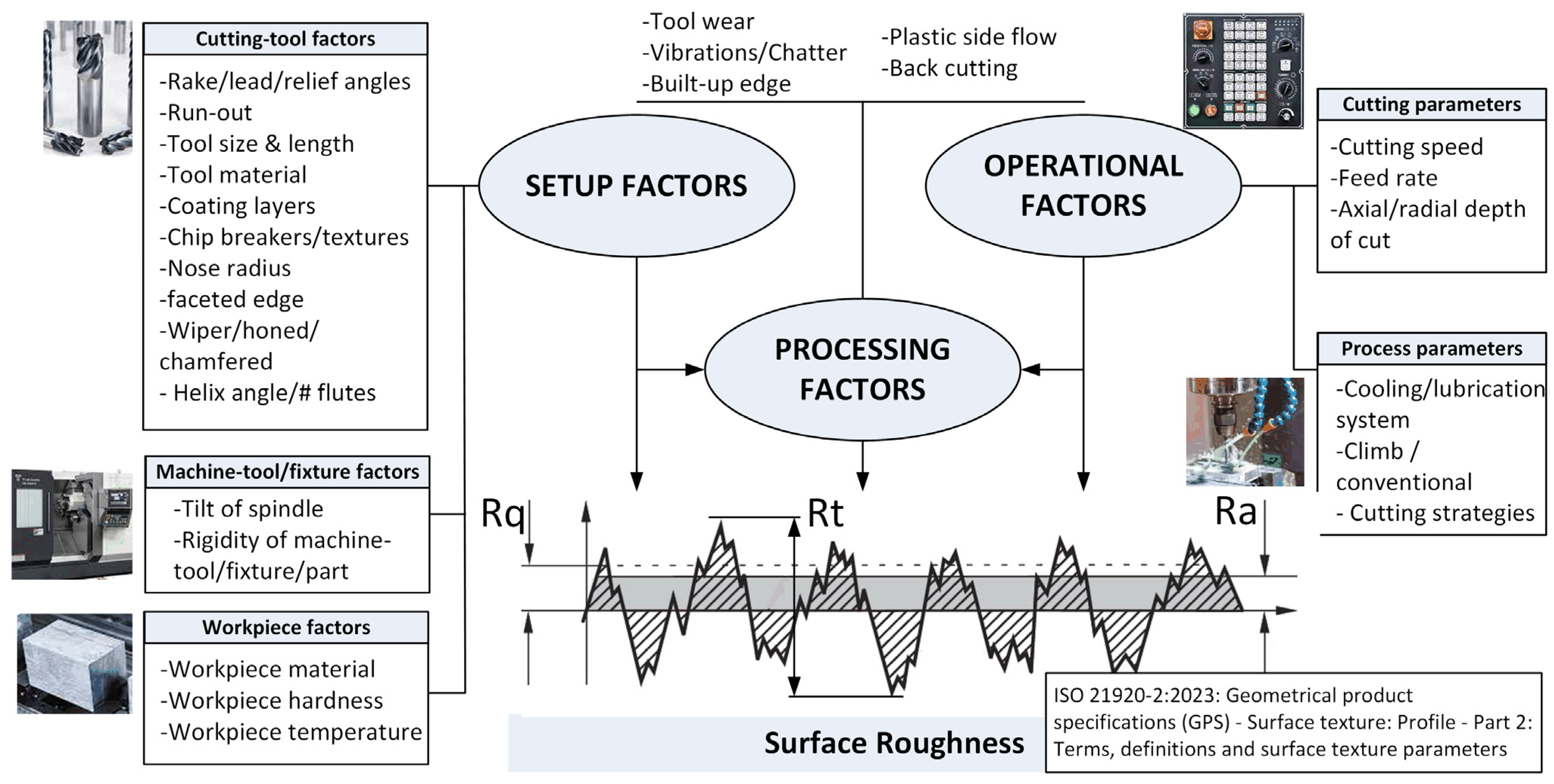
Figure 1. Factors that influence surface roughness generation.
3. Setup Factors
3.1. Cutting Tool Factors
Cutting tool factors are the most important ones at the planning stage that contribute to surface roughness generation. Within cutting tool factors, three subgroups can be identified: tool geometry, insert geometry and insert material.
-
Tool geometry
- o
-
Rake angle: In general, the use of positive rake angles in machining tends to reduce the cutting pressure, which avoids problems related to workpiece/cutting tool deflection and vibrations. It also prevents adhesion by reducing the built-up edge phenomenon, and thus, positive rake angles tend to produce a better surface roughness [34]. On the contrary, negative rake angles increase the cutting-edge strength but increase cutting forces and make it easy for the workpiece material to adhere to the cutting tool, increasing the surface roughness [7]. For instance, Adesta et al. [35] reported a trend of higher roughness values when increasing the negative value of rake angles when turning medium-carbon steel with cermet tools.
- o
-
Lead angle: When a larger lead angle (smaller entering angle) is applied, the load is spread over a greater length of the edge, creating a smoother cutting action. Since the load is reduced, cutting with larger lead angles can help reduce vibration possibilities, improving the surface roughness [34]. Furthermore, lead angles define the axial and radial components of cutting tools, which will impact tool/workpiece deflections [34].
- o
-
Relief angle: The relief angle provides a gap between the insert and the workpiece to avoid rubbing after shearing the material and makes the cutting edge move along the workpiece easily [36]. The relief angle mainly influences the tool wear rate, which will indirectly influence the surface roughness. In general, it is considered that the surface roughness increases as the relief angle becomes close to 0°.
-
-
Tool overhang: Tool overhang is directly related to vibrations that negatively impact surface roughness. Chang and Lu [37] showed that the average roughness at both the feeding and axial directions increases due to the increase in the overhang length due to the reduction in the rigidity of the tool. Some authors have studied how to locate the optimum range of tool overhang to minimize tool vibrations [38] and studied the dependence of tool overhang on both surface roughness and tool wear [39].
- o
-
Radial and axial run-out: One of the main factors that affects the surface finish in milling operations is the deviation in the location of the cutting tool teeth, especially in indexable cutting tools. The run-out refers to small deviations in the relative positions of the different inserts or cutting tool teeth that compose the tool, mainly due to the manufacturing tolerances or inaccurate assembly in the cutting body when inserts are replaced [40]. Baek et al. [41] showed the influence of run-out in milling operations in AISI 1041 steels and presented a surface roughness model considering the run-out effect to optimize the feed rate to obtain a maximum material removal rate. Krüger and Denkena [42] defined the relationships between cutting forces for a given run-out tool and the surface roughness generated in end mill operations. They presented and experimentally validated a model-based approach to identify the actual tool run-out and surface roughness from measuring cutting forces. Schmitz et al. [43] presented a model to explain the relationship between surface roughness generation and run-out in 6061-T6 aluminum alloys. The authors showed that, due to the presence of run-out, new regions of instability related to chatter occur if the harmonics of the run-out frequency reach the dominant natural frequency of the system.
- o
-
Helix angle and flutes: In end milling operations, the helix angle and flute number may have significant impacts on the surface roughness. Sur et al. [44] compared the performance in the peripheral milling of Ti-6Al-4V alloys with fixed and variable helix tools and showed that large helix angles performed best. Chen et al. [45] studied the effect of different tool helix angles in tilt side milling of Al 6061 thin-walled plates. Their experimental results showed that the helix angle had a high impact on the surface roughness, varying from 1–2 µm for a 10° helix angle to less than 1 µm for 40–50° helix angles. On the other hand, the number of flutes is also an important factor, since these channels in the tool allow the chips from the cutting zone to be removed. More flutes mean higher removal rates but less efficient chip evacuation, which may produce excessive heat or clogging that can affect the surface roughness. For instance, Danyan et al. [46] showed that end milling operations in Ti-6Al-4V with three flute tools performed slightly better in terms of the surface roughness than four flute tools. Similarly, Çelik et al. [47] showed that when end milling of glass fiber reinforced plastic composites with cemented carbide tools, the use of two flutes resulted in a reduction of 50% in surface roughness with respect to the same tool with four flutes.
-
-
Insert geometry:
- o
-
Insert shape: The shape of the insert may be important since it is related to the vibration tendency during machining. Due to the small nose angle, rhombic or triangular designs may present less vibration tendency, which may improve surface generation. On the other hand, geometries with a large point angle, such as round or square inserts, present a stronger cutting edge, but they need more machine power, and thus, there is a higher tendency to vibrate, which may increase the surface roughness [34].
- o
-
Corner configuration: The corner configuration heavily influences the strength of the cutting edge and surface finish. An insert with a nose radius is best in roughing applications where the surface finish is not critical. The radius encourages a longer tool life since heat from the machining operation dissipates across a greater surface area [34]. A big nose radius improves the surface roughness and cutting edge strength, but an excessively large radius may produce vibrations and chattering [36]. Shah et al. [48] experimentally showed that in turning operations of Ti-6Al-4V, tool nose variations ranging from 0.4 mm to 1.2 mm had a higher effect on the surface roughness that changed based on the feed rate or cutting speed. Deflection is also a primary concern limiting the size of the nose radius, since an increase in the nose radius increases radial cutting forces. In finishing operations, cutters with corner chamfered inserts or wiper inserts are commonly preferred. Chang and Fuh [49] studied different tool geometries under different side cutting edge angles, nose radii, side rake angles and chamfer angles in turning operations of pure aluminum and carbon steels. In the experimentation, the authors found that specific chamfered edge tools have the advantage of a limited chip contact length within the tool face, the cutting shear area, cutting forces and temperature decrease and it helps to reduce the built-up edge formation, improving the surface roughness. Wiper inserts can produce finer finishes than corner chamfer inserts at higher feed rates due to the special nose design with a long land. In fact, this geometry can reduce the surface roughness by a factor of two or more [50][51], and the degree of improvement increases with the feed rate [3]. However, if large cutters are applied with several wiper inserts, the resulting finish depends significantly on the run-out errors of the cutter. Wipers are mainly used when short chips are produced, such as in machining cast iron or brass. In materials such as steel, chip flow may be difficult, which may produce large tangential and axial forces and, eventually, may generate chatter [3][34].
- o
-
Edge preparation: Unlike solid tools, where sharp edges are commonly found, indexable tools for both turning and milling operations may present different edge preparations such as hones (honed radius, waterfall and variable honed radius), chamfers and negative lands (similar to chamfered edges but with smaller angles), as well as combinations of these three [52] (Figure 2). It is well known that edge preparation has a significant influence on the tool life, surface finish and surface integrity of the machined part [53]. Chamfered edges and negative lands provide an effective negative angle to the cutting action to provide a stronger edge geometry, which makes the insert less prone to premature breakage. Increasing the edge preparation width increases the cutting resistance, but vibrations may occur, which may have a negative impact on the surface roughness. In general, large edge hone tools produce higher surface roughness values than small edge hone tools or sharper tools [54]. However, honing is necessary to increase the cutting edge strength, even though the sharpness decreases. When the undeformed chip thickness is small, the cutting edge has a large impact on the process stability and produces a higher surface roughness value [55]. Özel et al. [56] studied the effects of cutting edge preparation, workpiece hardness, feed rate and cutting speed on the surface roughness and resultant forces in the finished hard turning of AISI H13 steel. In their experimentation, the authors found out that honed edge geometry with a honed radius of 10.5 ± 4.0 μm resulted in a better surface roughness than that obtained with tools with a chamfered edge of 20°.
- o
-
Chip breakers and textures: Chip breakers aid in curling the chips and discharge them quickly, improving chip control. If chips can be broken properly, they will not wrap around the workpiece, reducing vibrations and possible workpiece damage. Therefore, chip breakers can enhance the surface finish, reduce the built-up edge and reduce burrs [36]. Gürbüz et al. [57] studied the influence of different chip breaker geometries on surface roughness generation in turning AISI 1050 steels, and they developed an artificial neural network for prediction purposes, showing that a notable difference among five different chip breakers existed. A more novel approach consists of creating textures at the rake face to be used in conjunction with nanofluids in MQL systems, which reduce the tool wear and improve the surface roughness [58]. Readers may refer to [59] for a review about the influence of chip breaking methods in turning.
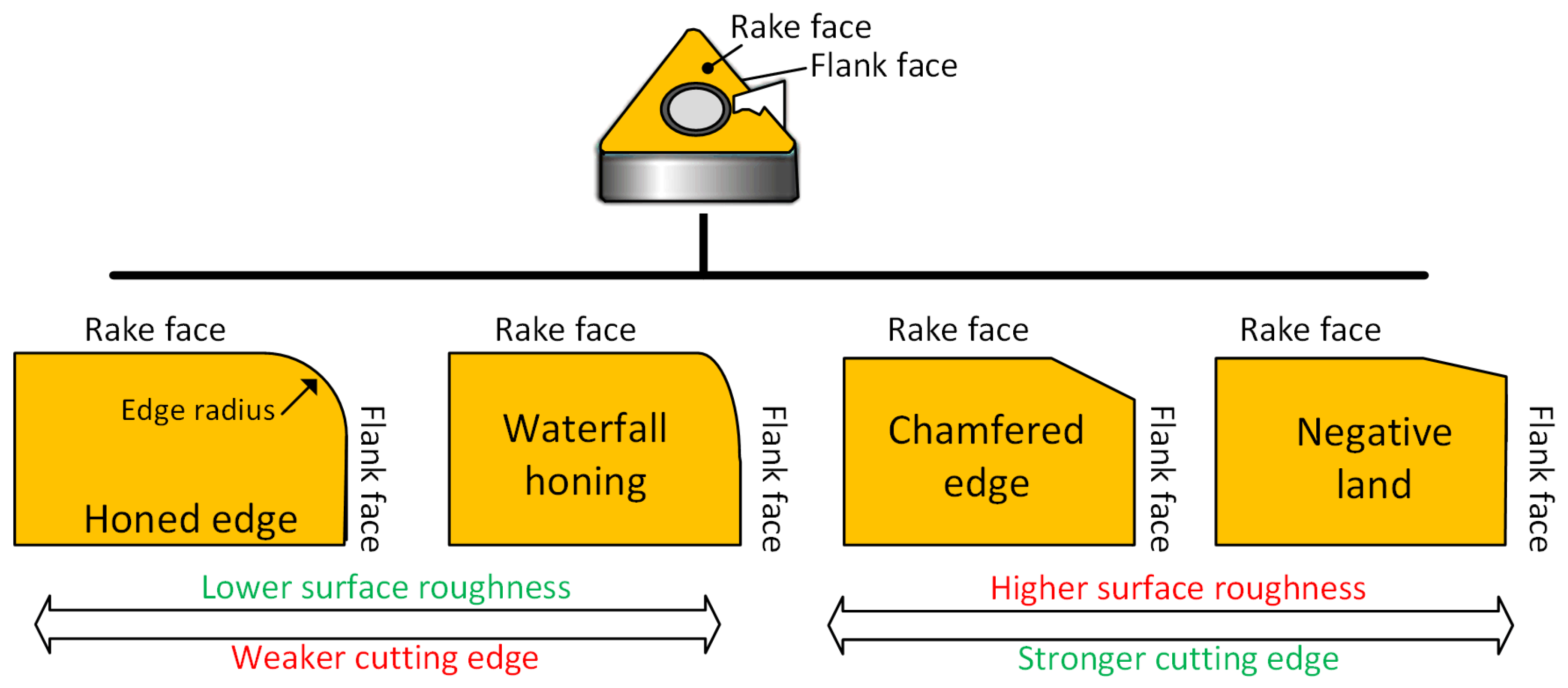
Figure 2. Common tool edge preparations.
-
Insert/cutter material (material and coating layers): The choice of tool material is very important in order to avoid chip material adhesion, which may produce poor surface finishes. To prevent this phenomenon, a tool grade with low affinity to the workpiece material should be chosen. For machining steel, carbide tools (WC) coated with TiC and TiN are effective. TiC and TiN have a lower solubility to iron than WC, which may help to prevent chip welding. Nalbant et al. [60] reported that increasing the number of coating layers decreases the friction coefficient and parallelly decreases the average surface roughness value of the workpiece. This experimentation was conducted in a CNC lathe using AISI 1030 steels as workpiece materials. The cutting tool materials compared were uncoated WC and WC coated with TiN, TiAlN and AlTiN. The best surface quality was obtained with the TiN-coated multilayered tools—using the CVD method—mainly because of its smaller friction coefficient and thermal conductivity. A similar conclusion was obtained in [61], where uncoated and TiAlN-coated end mills were analyzed in machining Al6061, and the surface roughness was considerably better under the coated tools. However, other researchers did not experimentally find a significant difference, as shown in [62], where micromilling operations in Inconel 718 with different end mill coatings (AlTiN, nACo and TiSiN) were studied.
3.2. Machine Tool/Fixturing Factors
Machine tool/fixturing factors are usually the most difficult to modify for better surface roughness generation, and they are usually seen as fixed factors whose impacts should be minimized by other means. Two main factors may be identified:
-
The tilt of the spindle: In milling, if the cutter is perfectly flat against the workpiece, the finished surface is usually recut by the back side of the cutter due to the axial run-out of tool inserts or slight axial deflection. The spindle can also be slightly tilted towards the back side of the tool, which brings the back side of the cutter below the upper side of the cutter, producing the back cutting phenomenon (Figure 3). Furthermore, after the cut, the edges may carry small chips that may scratch the surface at the back side, and the increased cutter contact may induce chatter [63]. These phenomena subsequently reduce the surface quality and tool’s life. In order to avoid these phenomena, the spindle may be tilted very slightly in the direction of the feed to provide small relief behind the cut [63]. However, too much spindle tilt may be not compensated during cutting and may produce scallops, which are magnified as cutter diameter increases, producing waviness errors that may affect product performance [64].
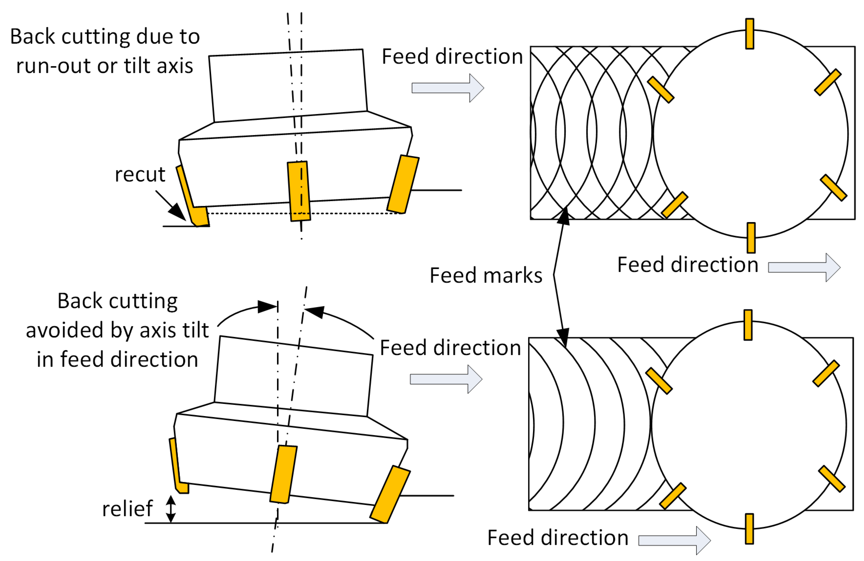
Figure 3. Back cutting effect and slight tilt of spindle in feed direction to minimize it (exaggerated representation).
-
Rigidity of machine tool/fixturing/workpiece: The rigidity of the system defined by the machine tool, fixturing and workpiece will influence the stability of the cut and the magnitude of vibrations or chatter generated [34]. Baek et al. [65] developed a dynamic surface roughness model for a face-milling operation of AISI 1041 steels by considering the static and dynamic characteristics of the cutting process. They studied the surface roughness generation of face milling processes and modeled the roughness parameters by considering the run-out effect, the forced vibration occurring in the intermittent cutting process and the static deflection. The authors modeled the face-milling operation as a dynamic system of one degree of freedom while considering the damping and stiffness effects of the cutting tool. The identification of the parameters of the cutting system was obtained by tests of the impact to the tool and workpiece.
3.3. Workpiece Factors
Workpiece factors are related to the type of material, hardness and initial temperature since these factors will determine the plastic deformation that occurs at the cutting zone. The main effects of these factors are as follows:
-
Workpiece materials: The surface roughness may completely differ across different workpiece materials since the particularities of chip formation will depend on material properties. Routara et al. [66] studied the influence of machining parameters on surface quality produced in end milling operations under three different workpiece materials, namely brass, aluminum and mild steel. As expected, the results showed that the response surface models derived for roughness prediction are specific to workpiece materials. Interestingly, the effect of cutting parameters on the roughness parameters was also different for different materials. On the other hand, the use of free-machining additives generally improves machinability since these additives assist in chip formation and lubricate the tool face, reducing adhesion and cutting forces [67]. Recent research works addressed the behavior of composite materials and the influence of process parameters on surface generation and chip formation. They explored mechanisms to mitigate delamination drilling-induced damage, which is detrimental to surface integrity, and explored the use of sustainable fibers with better delamination properties [68].
-
Hardness: For the same workpiece material, differences in hardness may contribute notably to surface roughness generation. In general, high hardness values may increase the wear rate and have a negative impact on the surface roughness, whereas low hardness values may produce a built-up edge formation, increasing the surface roughness. Furthermore, milling hard workpiece materials with low entering angles produces high axial cutting forces, which may lead to back cutting and increase surface roughness. Chavoski and Tajdari [69] analyzed the influences of the spindle speed and workpiece hardness on the surface roughness in turning AISI 4140 with CBN tools. From the experimentation, it was observed that, when increasing hardness, there is a decrease in the surface roughness, but when hardness exceeds 55 HRC, the surface roughness increases considerably. Özel et al. [56] reported that a lower workpiece surface hardness results in better surface roughness when turning AISI H3 steels from 50 to 55 HRC. Similarly, Desale and Jahagirdar [70] studied the influences of different workpiece hardness values (from 55 HRC to 62 HRC) on the surface roughness of tool steels, showing a higher roughness value when hardness increases. Chen [71] studied surface roughness values when cutting hardened steel (45–55 HRC) with different CBN tools and stated that the harder the workpiece material, the lower the surface roughness obtained for a given set of operating parameters.
-
Workpiece temperature: The workpiece temperature may influence the cutting process since the material becomes softer and easier to cut. Amin et al. [72] studied the influence of workpiece preheating on surface roughness in the end milling of hardened steel D2. The authors showed that preheating the workpiece produces roughness values that are substantially lower in part due to lower tool wear rates, which is mainly explained by the lower hardness in the preheating state. In recent years, to improve the machinability of hard materials, thermal-assisted machining processes have been proposed, resulting in significant reductions in cutting forces and surface roughness. Baek et al. [73] applied high-frequency induction and a laser beam to heat the workpiece before cutting in milling AISI 1045 steels and Inconel 718. Under both heating methods and materials, the cutting forces were reduced, and the surface roughness improved. Parida and Maity [74] showed that heating Inconel 718 alloys to 600 °C before turning resulted in a decrease of around 20% in the surface roughness with respect to the surface roughness obtained without previous heating. Mac et al. [75] studied the milling process of AISI D2 steels while heating the workpiece up to 400 °C using an induction coil. The resulting surface roughness value obtained in these processes was observed to be 0.1 µm at 400 °C, which is much lower than that obtained using the conventional process, which resulted in 0.17 µm. Similarly, Kalantari et al. [76] analyzed laser-assisted turning operations in Ti-6Al-4V, and they also showed a surface roughness improvement at all machining conditions tested.
4. Operational Factors
4.1. Cutting Parameters
Operational factors are commonly modified by operators and process planners in order to set the best trade-off between quality, costs and productivity. Among them, cutting parameters are the most straightforward parameters to change in order to reach a specific surface roughness quality. The main cutting parameters with a direct impact on the surface roughness are as follows:
-
Feed rate: The feed rate, together with the geometry of the cutting tool nose, is responsible for the geometry of the tooth marks at the workpiece surface. The feed rate is a dominant parameter in machining, and it produces a high increase in surface roughness when it increases [77]. In fact, the feed rate is the main factor used in kinematic models for surface roughness prediction, and in almost all experimental studies, the feed rate is one of the most significant parameters related to surface roughness. When the feed rate decreases, the surface roughness decreases since the feed marks responsible for roughness are less pronounced. However, at very low feeds, other effects such as side flow arise, and the surface roughness is kept constant or even increases [79].
-
Axial depth of cut: The influence of the depth of cut on the surface roughness is usually less important than the feed rate or cutting speed. In fact, some investigations show that it is not a significant factor, while other investigations show the opposite. For instance, Tammineni and Yedula [80] studied face milling operations in Al 1050 aluminum alloys, and they showed that surface roughness depends on the cutting factor feed rate and cutting speeds, but the effect of the depth of cut was observed to be unclear. Ding et al. [81] reported that the axial depth of cut contributes the most to the surface roughness in the hard milling of AISI H13. In their experimentation, an end mill operation was studied, and the increase in the axial depth of cut produced an increase in the cutting forces and in the surface roughness, probably because of the vibrations and deflections of the cutter. However, other researchers have presented different trends. Darwish [82] studied finishing turning operations in Inconel 718 alloys and reported that the depth of cut was the second most important factor affecting the surface roughness after the feed rate, and the effect of the depth of cut was more pronounced at high feed rates, where the surface quality improved when the depth of cut increased.
-
Radial depth of cut: In milling, the radial depth of cut is also referred to as stepover or cutting engagement. As a general practice, cutting with the full diameter of the tool should be avoided since the cutting starts with a zero chip thickness, which produces higher surface roughness and higher tool wear rates [34]. Therefore, the radial depth of cut at two-thirds of the tool is commonly recommended in milling operations due to its minimum effect on surface roughness and good material removal rate. However, some researchers have shown the radial depth of cut to have an important role in end milling operations. Jasni and Lajis [78] studied an end mill operation in AISI D2 hardened steels under different cutting speeds and radial depths of cut, and both parameters were equally defined as critical, increasing the surface roughness when the cutting speed decreases or when the radial depth of cut increases, probably due to the increase in cutting forces and tool deflection. A similar trend was observed in [37], where a higher radial depth of cut in side milling operations produced rougher surfaces in S45C steels. More recently, the effect of the relative radial position of the cutter with respect to the workpiece when cutters are bigger than workpiece dimension in flat milling was reported in [83]. This relative position of the cutter produces a predominantly up-milling or down-milling cut, which leads to variations in cutting forces, vibrations and surface roughness. In the experimental results regarding SAE 1045 workpieces, a significant influence existed on surface roughness generation, and the worst surface quality was obtained when the down-milling portion was higher. In ball milling, it is well known that the radial depth of cut is a critical parameter that needs to be set carefully since surface roughness in the transversal direction will be directly related to this value [84] since it acts as the feed rate in that direction.
4.2. Process Parameters
Process parameters are a subgroup of operational factors related to the way the cutting process is conducted. For instance, these include milling modes (climb or conventional milling), tool path strategies and cooling/lubricating systems. Their main characteristics and relationships with surface roughness generation are as follows:
-
Climb/conventional milling: Climb milling (i.e., down milling) is generally preferred in finishing operations since the cutter starts the cut when the undeformed chip thickness is higher [34]. Unlike climb milling, in conventional milling (i.e., up milling), the cutter starts the cut with a zero chip thickness, causing rubbing or burnishing before the chip can reach its full thickness, which may lead to higher surface roughness [63]. Michalik et al., in their study of thin-walled components from steel C45 [85], recommended the use of the climb milling method to increase the surface quality. Abbas et al. [86] also reported a 22% increase in the surface roughness when conventional milling was used compared to when down milling was used in milling single slots in AISI P20 mold steels.
-
Cutting strategies: With the use of Computer-Aided Manufacturing (CAM) systems, many different and complex cutting strategies are easily adopted in conventional machining operations, such as trochoidal, trichoidal, follow-part, zig, zig-zag, plunge, etc. Some investigations have shown that the selected strategy can have a significant impact on the surface roughness. Karkalos et al. [87] analyzed the surface roughness quality of two strategies for slot machining in Al 6082 alloys: conventional and trochoidal. The results showed that the trochoidal strategy provided a superior surface quality. Uzun at al. [88] studied four different strategies in milling AISI X210Cr12 steels, namely trochoidal, follow part, zig and zig-zag, and observed that the best surface roughness value was achieved under the follow part and trochoidal strategies.
-
Coolant: Besides being used to reduce the temperature at the tool–chip interface, cutting fluids are employed in machining operations to reduce the adhesion of the work material to the edges of the tool, improving the surface roughness. Cutting lubricants are particularly effective at low cutting speeds and feed rates where the emergence of the built-up-edge phenomenon may be reduced. From previous works in turning steels [89][90], it can be seen that under dry cutting strategies, the adhesion of the work material to the tool has the highest adhesion rate, increasing the surface roughness. However, the quantity of the adhered material is reduced under flood cooling. Under other coolant strategies, such as minimum quantity lubrication (MQL), the amount of material adhered is commonly higher than that under flood cooling but lower than dry machining [91]. Yan et al. [92] proved that MQL systems, when used in milling 50CrMnMo steels, can reduce tool wear, improve tool life and generate a better surface finish mainly by reducing the friction in the chip–tool and workpiece–tool interfaces, i.e., reducing the adhesion. A maximum quantity of lubricant from which there is no additional reduction in the adhered material has also been identified [91]. Furthermore, MQL requires a correct setup in terms of both the flow rate and nozzle position. Hadad and Sadeghi [90] found that the nozzle position may be critical to MQL performance in turning AISI4140 steel alloys, and lower surface roughness values can be achieved through the supply of oil mist to both the rake and flank faces. Similarly,
5. Processing Factors
Processing factors are related to those that are specific to the cutting phenomenon. These factors are highly related to setup and operational factors. For instance, a built-up edge phenomenon may appear if the cutting speed is too low, with a very high impact on the surface roughness. However, when using the correct cutting tool and cutting parameters, a BUE may not appear. The following relevant processing factors can be found:
-
Built-up edge (BUE): BUE formation may be produced at the tip of the tool, as shown in Figure 4, modifying the tool nose radius and generating higher surface roughness values. The primary cause of a BUE in machining is the adhesion of workpiece material to the tool’s cutting edge during machining operations. The high pressures and temperatures at the cutting interface cause this adhesion. Various factors, including the material being machined, cutting conditions and tool material, can influence the exact mechanisms responsible for the development of a BUE. This phenomenon is particularly important when machining soft materials or using low cutting speeds, although other factors, such as tool geometry and material, cutting conditions or use of lubricants, may interact [93].
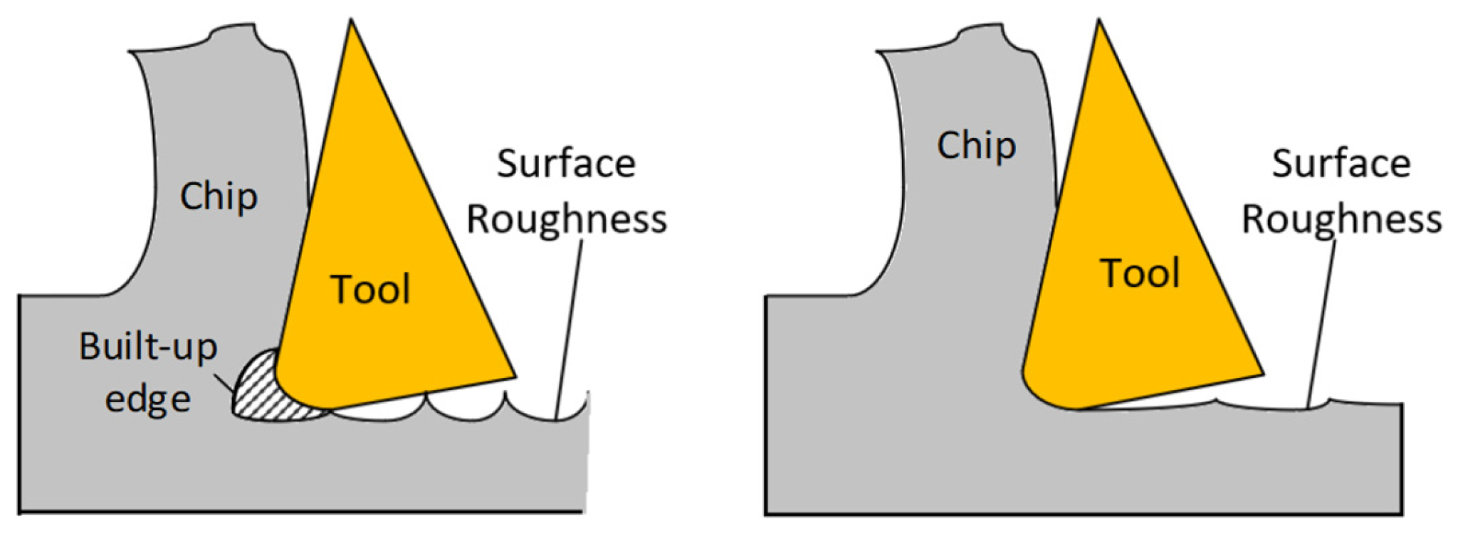
Figure 4. Built-up edge formation and differences in surface roughness generation.
-
Vibrations: Vibrations may have a clear impact on dimensional accuracy, surface roughness, and tool life. Many research works have analyzed the effect of vibrations on surface roughness. Baek et al. [65] studied the generation of surface roughness profiles in face milling operations with AISI 1041 workpiece materials and modeled the process while considering both static and dynamic components. The authors derived a surface roughness model for prediction purposes based on the relative displacement between the workpiece and the cutting tool while considering cutting forces, insert run-out error, insert edge profile and cutting conditions (cutting speed, feed rate and depth of cut). Chang et al. [94] proposed measuring the vibrations from the spindle using a capacitive displacement sensor to predict the surface roughness. The system was modeled as a cantilever beam, and the first mode shape was assumed to be the main vibration that determines surface roughness generation. A simple linear model between the measured surface roughness and the roughness calculated using spindle motion was developed. Similarly, Abouelatta and Mádl [95] reported a correlation between vibrations and surface roughness in turning free-cutting steel, and a surface roughness model based on vibrations and cutting parameters was built for prediction purposes with a good performance.
-
Tool wear: Many research works have shown that an increase in tool wear produces an increase in surface roughness over cutting time [96][97]. However, many others suggest that at the beginning of the wear-out process, the roughness values exhibit a falling and rising trend with the machining time [71][98]. Yan et al. [92] observed that high roughness values are generated when the cutting insert is totally new. When the insert starts to be worn, the radius of the tool nose increases and the surface roughness is improved, reducing the teeth marks. Afterwards, a high increase in the tool wear produces irregularities in the nose radius, and the surface roughness rapidly increases. Other studies have shown that the forces and the surface roughness tend to increase as the tool wear increases [99][100]. Since the cutting temperature is the main factor that influences tool wear progression, coolants are commonly used to reduce the tool wear rate.
-
Plastic side flow: The surface roughness is closely related to the feed rates. However, when low or very low feed rates are applied, the shearing mechanism is replaced by a ploughing mechanism since the chip is not thick enough for removal. Thus, the material is plastically deformed rather than forming a sheared chip, and the accumulation of the deformed material around the tool produces a rougher surface, as shown in Figure 5 [101]. Kishawy et al. [102] studied hard turning operations in 52,100 steels and they showed that more side flow is generated when a higher nose radius is used, increasing the surface roughness. Similarly, Thiele and Melkote [101] proved that a larger cutting edge radius results in more ploughing, and thus, more material is pressed under the tool, which leads to an increased surface roughness.
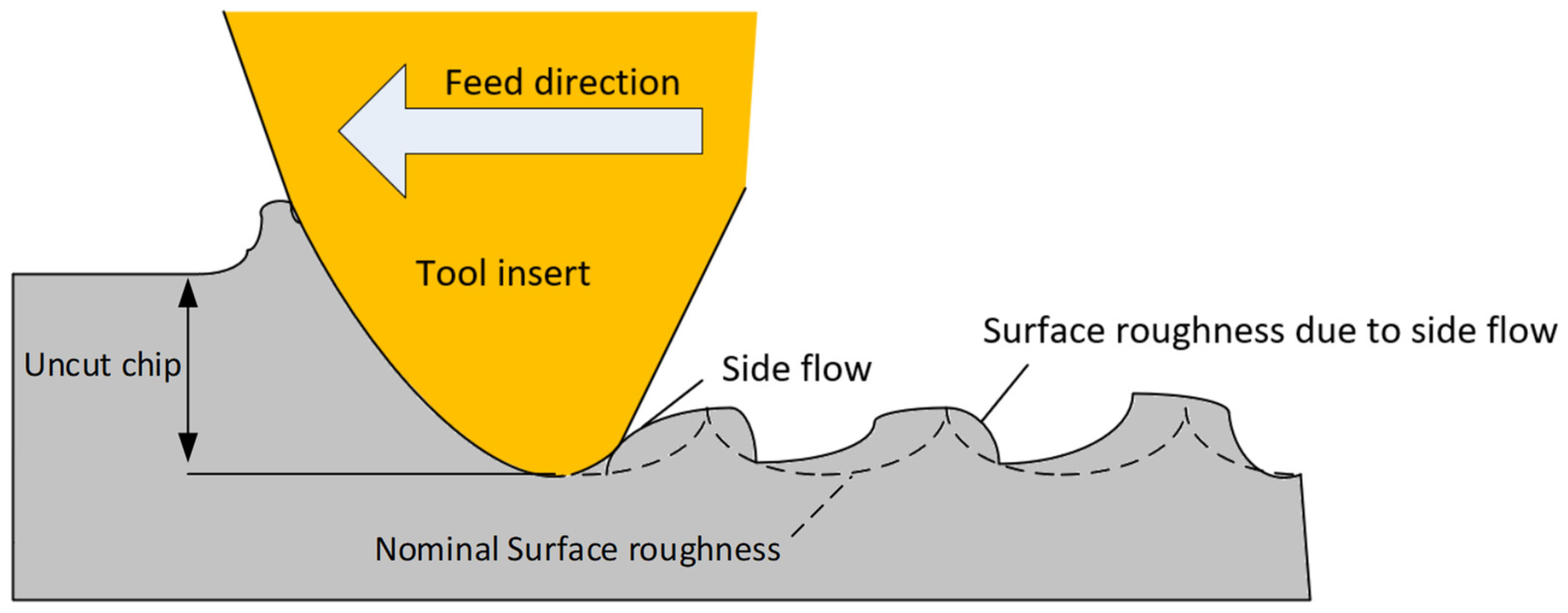
Figure 5. Plastic side flow in machining.
References
- ISO 25178-2; Geometrical Product Specifications (GPS)—Surface Texture: Areal Part—2: Terms, Definitions and Surface Texture Parameters. International Organization for Standardization: Geneva, Switzerland, 2023.
- Wang, X.; Feng, C.X. Development of Empirical Models for Surface Roughness Prediction in Finish Turning. Int. J. Adv. Manuf. Technol. 2002, 20, 348–356.
- Stephenson, D.A.; Agapiou, J.S. Metal Cutting Theory and Practice; CRC Press: Boca Raton, FL, USA, 2016.
- He, C.L.; Zong, W.J.; Zhang, J.J. Influencing Factors and Theoretical Modeling Methods of Surface Roughness in Turning Process: State-of-the-Art. Int. J. Mach. Tools Manuf. 2018, 129, 15–26.
- Khorasani, A.M.; Yazdi, M.R.S.; Safizadeh, M.S. Analysis of Machining Parameters Effects on Surface Roughness: A Review. Int. J. Comput. Mater. Sci. Surf. Eng. 2012, 5, 68.
- Boothroyd, G. Fundamentals of Metal Machining and Machine Tools; CRC Press: Boca Raton, FL, USA, 1988; Volume 28.
- Shaw, M.C. Metal Cutting Principles; Oxford University Press: New York, NY, USA, 2005; Volume 2.
- Ghatge, D.; Ramanujam, R. Sustainable Machining: A Review. Mater. Today Proc. 2023, in press.
- Jawahir, I.S.; Schoop, J.; Kaynak, Y.; Balaji, A.K.; Ghosh, R.; Lu, T. Progress Toward Modeling and Optimization of Sustainable Machining Processes. J. Manuf. Sci. Eng. Trans. ASME 2020, 142, 110811.
- Sarikaya, M.; Gupta, M.K.; Tomaz, I.; Danish, M.; Mia, M.; Rubaiee, S.; Jamil, M.; Pimenov, D.Y.; Khanna, N. Cooling Techniques to Improve the Machinability and Sustainability of Light-Weight Alloys: A State-of-the-Art Review. J. Manuf. Process. 2021, 62, 179–201.
- Rajemi, M.F.; Mativenga, P.T.; Aramcharoen, A. Sustainable Machining: Selection of Optimum Turning Conditions Based on Minimum Energy Considerations. J. Clean. Prod. 2010, 18, 1059–1065.
- Pimenov, D.Y.; Mia, M.; Gupta, M.K.; Machado, Á.R.; Pintaude, G.; Unune, D.R.; Khanna, N.; Khan, A.M.; Tomaz, Í.; Wojciechowski, S.; et al. Resource Saving by Optimization and Machining Environments for Sustainable Manufacturing: A Review and Future Prospects. Renew. Sustain. Energy Rev. 2022, 166, 112660.
- Korkmaz, M.E.; Gupta, M.K.; Ross, N.S.; Sivalingam, V. Implementation of Green Cooling/Lubrication Strategies in Metal Cutting Industries: A State of the Art towards Sustainable Future and Challenges. Sustain. Mater. Technol. 2023, 36, e00641.
- Carou, D.; Rubio, E.M.; Davim, J.P. A Note on the Use of the Minimum Quantity Lubrication (MQL) System in Turning. Ind. Lubr. Tribol. 2015, 67, 256–261.
- Davim, J.P.; Sreejith, P.S.; Gomes, R.; Peixoto, C. Experimental Studies on Drilling of Aluminium (AA1050) under Dry, Minimum Quantity of Lubricant, and Flood-Lubricated Conditions. Proc. Inst. Mech. Eng. B J. Eng. Manuf. 2006, 220, 1605–1611.
- Davim, J.P. Surface Integrity in Machining; Springer: Berlin/Heidelberg, Germany, 2010; Volume 1848828742.
- Davim, J.P. Sustainable Machining; Springer: Berlin/Heidelberg, Germany, 2017.
- Najiha, M.S.; Rahman, M.M.; Yusoff, A.R. Environmental Impacts and Hazards Associated with Metal Working Fluids and Recent Advances in the Sustainable Systems: A Review. Renew. Sustain. Energy Rev. 2016, 60, 1008–1031.
- Goindi, G.S.; Sarkar, P. Dry Machining: A Step towards Sustainable Machining—Challenges and Future Directions. J. Clean. Prod. 2017, 165, 1557–1571.
- Kroll, L.; Blau, P.; Wabner, M.; Frieß, U.; Eulitz, J.; Klärner, M. Lightweight Components for Energy-Efficient Machine Tools. CIRP J. Manuf. Sci. Technol. 2011, 4, 148–160.
- Trampus, V. Energy Saving Tactics for Machine Tools. Manuf. Eng. 2013, 150, 144.
- Feng, C.; Huang, S. The Analysis of Key Technologies for Sustainable Machine Tools Design. Appl. Sci. 2020, 10, 731.
- Denkena, B.; Abele, E.; Brecher, C.; Dittrich, M.A.; Kara, S.; Mori, M. Energy Efficient Machine Tools. CIRP Ann. 2020, 69, 646–667.
- Khan, A.M.; He, N.; Jamil, M.; Raza, S.M. Energy Characterization and Energy-Saving Strategies in Sustainable Machining Processes: A State-of-the-Art Review. J. Prod. Syst. Manuf. Sci. 2021, 2, 33.
- Masoudi, S.; Esfahani, M.J.; Jafarian, F.; Mirsoleimani, S.A. Comparison the Effect of MQL, Wet and Dry Turning on Surface Topography, Cylindricity Tolerance and Sustainability. Int. J. Precis. Eng. Manuf. Green Technol. 2023, 10, 9–21.
- Mallick, R.; Kumar, R.; Panda, A.; Sahoo, A.K. Current Status of Hard Turning in Manufacturing: Aspects of Cooling Strategy and Sustainability. Lubricants 2023, 11, 108.
- Padhan, S.; Dash, L.; Behera, S.K.; Das, S.R. Modeling and Optimization of Power Consumption for Economic Analysis, Energy-Saving Carbon Footprint Analysis, and Sustainability Assessment in Finish Hard Turning Under Graphene Nanoparticle–Assisted Minimum Quantity Lubrication. Process Integr. Optim. Sustain. 2020, 4, 445–463.
- Dash, L.; Padhan, S.; Das, A.; Das, S.R. Machinability Investigation and Sustainability Assessment in Hard Turning of AISI D3 Steel with Coated Carbide Tool under Nanofluid Minimum Quantity Lubrication-Cooling Condition. Proc. Inst. Mech. Eng. C J. Mech. Eng. Sci. 2021, 235, 6496–6528.
- Gupta, M.K.; Jamil, M.; Wang, X.; Song, Q.; Liu, Z.; Mia, M.; Hegab, H.; Khan, A.M.; Collado, A.G.; Pruncu, C.I.; et al. Performance Evaluation of Vegetable Oil-Based Nano-Cutting Fluids in Environmentally Friendly Machining of Inconel-800 Alloy. Materials 2019, 12, 2792.
- Kadam, G.S.; Pawade, R.S. Surface Integrity and Sustainability Assessment in High-Speed Machining of Inconel 718—An Eco-Friendly Green Approach. J. Clean. Prod. 2017, 147, 273–283.
- Edem, I.F.; Balogun, V.A. Sustainability Analyses of Cutting Edge Radius on Specific Cutting Energy and Surface Finish in Side Milling Processes. Int. J. Adv. Manuf. Technol. 2018, 95, 3381–3391.
- Iqbal, A.; Zhao, G.; Cheok, Q.; He, N.; Nauman, M.M. Sustainable Machining: Tool Life Criterion Based on Work Surface Quality. Processes 2022, 10, 1087.
- Duman, E.; Yapan, Y.F.; Salvi, H.; Sofuoğlu, M.A.; Khanna, N.; Uysal, A. Investigation of Ultrasonic Vibration Assisted Orthogonal Turning under Dry and Minimum Quantity Lubrication Conditions and Performing Sustainability Analyses. J. Clean. Prod. 2024, 434, 140187.
- Sandvick-Coromant. Metal Cutting Technical Guide (D) Milling; Sandvick-Coromant: Sandviken, Sweden, 2008.
- Adesta, E.Y.T.; Riza, M.; Hazza, M.; Agusman, D. Rosehan Tool Wear and Surface Finish Investigation in High Speed Turning Using Cermet Insert by Applying Negative Rake Angles. Eur. J. Sci. Res. 2009, 38, 180–188.
- Korloy Technical Information. Available online: https://sunsteel.eu/IMG/pdf/catalogue_technique_korloy.pdf (accessed on 9 January 2024).
- Chang, C.-K.; Lu, H.S. Study on the Prediction Model of Surface Roughness for Side Milling Operations. Int. J. Adv. Manuf. Technol. 2006, 29, 867–878.
- Mishra, V.; Khan, G.S.; Chattopadhyay, K.D.; Nand, K.; Sarepaka, R.V. Effects of Tool Overhang on Selection of Machining Parameters and Surface Finish during Diamond Turning. Measurement 2014, 55, 353–361.
- Kiyak, M.; Kaner, B.; Sahin, I.; Aldemir, B.; Cakir, O. The Dependence of Tool Overhang on Surface Quality and Tool Wear in the Turning Process. Int. J. Adv. Manuf. Technol. 2010, 51, 431–438.
- Franco, P.; Estrems, M.; Faura, F. Influence of Radial and Axial Runouts on Surface Roughness in Face Milling with Round Insert Cutting Tools. Int. J. Mach. Tools Manuf. 2004, 44, 1555–1565.
- Baek, D.K.; Ko, T.J.; Kim, H.S. Optimization of Feedrate in a Face Milling Operation Using a Surface Roughness Model. Int. J. Mach. Tools Manuf. 2001, 41, 451–462.
- Krüger, M.; Denkena, B. Model-Based Identification of Tool Runout in End Milling and Estimation of Surface Roughness from Measured Cutting Forces. Int. J. Adv. Manuf. Technol. 2013, 65, 1067–1080.
- Schmitz, T.L.; Couey, J.; Marsh, E.; Mauntler, N.; Hughes, D. Runout Effects in Milling: Surface Finish, Surface Location Error, and Stability. Int. J. Mach. Tools Manuf. 2007, 47, 841–851.
- Sur, G.; Motorcu, A.R.; Nohutçu, S. Single and Multi-Objective Optimization for Cutting Force and Surface Roughness in Peripheral Milling of Ti6Al4V Using Fixed and Variable Helix Angle Tools. J. Manuf. Process 2022, 80, 529–545.
- Chen, M.; Liu, G.; Dang, J.; Li, C.; Ming, W. Effects of Tool Helix Angles on Machined Surface Morphology in Tilt Side Milling of Cantilever Thin-Walled Plates. Procedia CIRP 2018, 71, 93–98.
- Daniyan, I.; Tlhabadira, I.; Mpofu, K.; Adeodu, A. Investigating the Geometrical Effects of Cutting Tool on the Surface Roughness of Titanium Alloy (Ti6Al4V) during Milling Operation. Procedia CIRP 2021, 99, 157–164.
- Çelik, Y.; Kılıçkap, E.; Yardımeden, A. Estimate of cutting forces and surface roughness in end milling of glass fiber reinforced plastic composites using fuzzy logic system. Sci. Eng. Compos. Mater. 2013, 21, 435–443.
- Shah, D.; Bhavsar, S. Effect of Tool Nose Radius and Machining Parameters on Cutting Force, Cutting Temperature and Surface Roughness-An Experimental Study of Ti-6Al-4V (ELI). Mater. Today Proc. 2020, 22, 1977–1986.
- Chang, C.S.; Fuh, K.H. An Experimental Study of the Chip Flow of Chamfered Main Cutting Edge Tools. J. Mater. Process. Technol. 1998, 73, 167–178.
- Taha Mohamed Abbas, A. Comparative Assessment of Wiper and Conventional Carbide Inserts on Surface Roughness in the Turning of High Strength Steel. J. Mater. Sci. Res. 2015, 5, 32.
- Grzesik, W.; Wanat, T. Surface Finish Generated in Hard Turning of Quenched Alloy Steel Parts Using Conventional and Wiper Ceramic Inserts. Int. J. Mach. Tools Manuf. 2006, 46, 1988–1995.
- Zhuang, K.; Fu, C.; Weng, J.; Hu, C. Cutting edge microgeometries in metal cutting: A review. Int. J. Adv. Manuf. Technol. 2021, 116, 2045–2092.
- Kumar, S.; Padmakumar, M. An Experimental Study of Applying Various Cutting Edges on Wiper Milling Inserts in Face Milling AISI 1070 Steel. Int. J. Mech. Ind. Eng. 2012, 2, 50–55.
- Dogra, M.; Sharma, V.S.; Dureja, J. Effect of Tool Geometry Variation on Finish Turning—A Review. J. Eng. Sci. Technol. Rev. 2011, 4, 1–13.
- Denkena, B.; Biermann, D. Cutting Edge Geometries. CIRP Ann. Manuf. Technol. 2014, 63, 631–653.
- Özel, T.; Hsu, T.K.; Zeren, E. Effects of Cutting Edge Geometry, Workpiece Hardness, Feed Rate and Cutting Speed on Surface Roughness and Forces in Finish Turning of Hardened AISI H13 Steel. Int. J. Adv. Manuf. Technol. 2005, 25, 262–269.
- Gürbüz, H.; Sözen, A.; Şeker, U. Modelling of Effects of Various Chip Breaker Forms on Surface Roughness in Turning Operations by Utilizing Artificial Neural Networks. J. Polytech. 2016, 19, 71–83.
- Peña-Parás, L.; Maldonado-Cortés, D.; Rodríguez-Villalobos, M.; Romero-Cantú, A.G.; Montemayor, O.E. Enhancing Tool Life, and Reducing Power Consumption and Surface Roughness in Milling Processes by Nanolubricants and Laser Surface Texturing. J. Clean. Prod. 2020, 253, 119836.
- Yılmaz, B.; Karabulut, Ş.; Güllü, A. A Review of the Chip Breaking Methods for Continuous Chips in Turning. J. Manuf. Process 2020, 49, 50–69.
- Nalbant, M.; Gökkaya, H.; Toktaş, I.; Sur, G. The Experimental Investigation of the Effects of Uncoated, PVD- and CVD-Coated Cemented Carbide Inserts and Cutting Parameters on Surface Roughness in CNC Turning and Its Prediction Using Artificial Neural Networks. Robot. Comput. Integr. Manuf. 2009, 25, 211–223.
- Haja Syeddu Masooth, P.; Jayakumar, V.; Bharathiraja, G. Experimental Investigation on Surface Roughness in CNC End Milling Process by Uncoated and TiAlN Coated Carbide End Mill under Dry Conditions. Mater. Today Proc. 2020, 22, 726–736.
- Muhammad, A.; Gupta, M.K.; Mikołajczyk, T.; Pimenov, D.Y.; Giasin, K. Effect of Tool Coating and Cutting Parameters on Surface Roughness and Burr Formation during Micromilling of Inconel 718. Metals 2021, 11, 167.
- Ingersoll-Cutting-Tools. Technical Information. Better Surface Finishes. M458; Ingersoll-Cutting-Tools: Rockford, IL, USA, 2009.
- Nguyen, H.T.; Wang, H.; Hu, S.J. Modeling Cutter Tilt and Cutter-Spindle Stiffness for Machine Condition Monitoring in Face Milling Using High-Definition Surface Metrology. Int. J. Adv. Manuf. Technol. 2014, 70, 1323–1335.
- Kyun Baek, D.; Jo Ko, T.; Sool Kim, H. A Dynamic Surface Roughness Model for Face Milling. Precis. Eng. 1997, 20, 171–178.
- Routara, B.C.; Bandyopadhyay, A.; Sahoo, P. Roughness Modeling and Optimization in CNC End Milling Using Response Surface Method: Effect of Workpiece Material Variation. Int. J. Adv. Manuf. Technol. 2009, 40, 1166–1180.
- Li, Z.; Wu, D. Effect of Free-Cutting Additives on Machining Characteristics of Austenitic Stainless Steels. J. Mater. Sci. Technol. 2010, 26, 839–844.
- Ismail, S.O.; Dhakal, H.N.; Popov, I.; Beaugrand, J. Comprehensive Study on Machinability of Sustainable and Conventional Fibre Reinforced Polymer Composites. Eng. Sci. Technol. Int. J. 2016, 19, 2043–2052.
- Chavoshi, S.Z.; Tajdari, M. Surface Roughness Modelling in Hard Turning Operation of AISI 4140 Using CBN Cutting Tool. Int. J. Mater. Form. 2010, 3, 233–239.
- Desale, P.S.; Jahagirdar, R.S. Modeling the Effect of Variable Work Piece Hardness on Surface Roughness in an End Milling Using Multiple Regression and Adaptive Neuro Fuzzy Inference System. Int. J. Ind. Eng. Comput. 2014, 5, 265–272.
- Chen, W. Cutting Forces and Surface Finish When Machining Medium Hardness Steel Using CBN Tools. Int. J. Mach. Tools Manuf. 2000, 40, 455–466.
- Amin, A.K.M.N.; Dolah, S.B.; Mahmud, M.B.; Lajis, M.A. Effects of Workpiece Preheating on Surface Roughness, Chatter and Tool Performance during End Milling of Hardened Steel D2. J. Mater. Process. Technol. 2008, 201, 466–470.
- Baek, J.T.; Woo, W.S.; Lee, C.M. A Study on the Machining Characteristics of Induction and Laser-Induction Assisted Machining of AISI 1045 Steel and Inconel 718. J. Manuf. Process. 2018, 34, 513–522.
- Parida, A.K.; Maity, K. Study of Machinability in Heat-Assisted Machining of Nickel-Base Alloy. Measurement 2021, 170, 108682.
- Mac, T.B.; Luyen, T.T.; Nguyen, D.T. Assessment of the Effect of Thermal-Assisted Machining on the Machinability of SKD11 Alloy Steel. Metals 2023, 13, 699.
- Kalantari, O.; Jafarian, F.; Fallah, M.M. Comparative Investigation of Surface Integrity in Laser Assisted and Conventional Machining of Ti-6Al-4 V Alloy. J. Manuf. Process 2021, 62, 90–98.
- Cakir, M.C.; Ensarioglu, C.; Demirayak, I. Mathematical Modeling of Surface Roughness for Evaluating the Effects of Cutting Parameters and Coating Material. J. Mater. Process. Technol. 2009, 209, 102–109.
- Jasni, N.A.H.; Lajis, M.A. Surface Topography in Machining of AISI D2 Hardened Steel. Appl. Mech. Mater. 2013, 315, 660–664.
- Grzesik, W. A Revised Model for Predicting Surface Roughness in Turning. Wear 1996, 194, 143.
- Tammineni, L.; Yedula, H.P.R. Investigation of Influence of Milling Parameters on Surface Roughness and Flatness. Int. J. Adv. Eng. Technol. 2014, 6, 2416.
- Ding, T.; Zhang, S.; Wang, Y.; Zhu, X. Empirical Models and Optimal Cutting Parameters for Cutting Forces and Surface Roughness in Hard Milling of AISI H13 Steel. Int. J. Adv. Manuf. Technol. 2010, 51, 45–55.
- Darwish, S.M. Impact of the Tool Material and the Cutting Parameters on Surface Roughness of Supermet 718 Nickel Superalloy. J. Mater. Process. Technol. 2000, 97, 10–18.
- Pimenov, D.Y.; Hassui, A.; Wojciechowski, S.; Mia, M.; Magri, A.; Suyama, D.I.; Bustillo, A.; Krolczyk, G.; Gupta, M.K. Effect of the Relative Position of the Face Milling Tool towards the Workpiece on Machined Surface Roughness and Milling Dynamics. Appl. Sci. 2019, 9, 842.
- Buj-Corral, I.; Vivancos-Calvet, J.; Domínguez-Fernández, A. Surface Topography in Ball-End Milling Processes as a Function of Feed per Tooth and Radial Depth of Cut. Int. J. Mach. Tools Manuf. 2012, 53, 151–159.
- Michalik, P.; Zajac, J.; Hatala, M.; Mital, D.; Fecova, V. Monitoring Surface Roughness of Thin-Walled Components from Steel C45 Machining down and up Milling. Measurement 2014, 58, 416–428.
- Abbas, A.T.; Abdelnasser, E.; Naeim, N.; Alqosaibi, K.F.; Al-Bahkali, E.A.; Elkaseer, A. Effect of Milling Strategy on the Surface Quality of AISI P20 Mold Steel. Metals 2024, 14, 48.
- Karkalos, N.E.; Karmiris-Obratański, P.; Kurpiel, S.; Zagórski, K.; Markopoulos, A.P. Investigation on the Surface Quality Obtained during Trochoidal Milling of 6082 Aluminum Alloy. Machines 2021, 9, 75.
- Uzun, M.; Usca, Ü.A.; Kuntoğlu, M.; Gupta, M.K. Influence of Tool Path Strategies on Machining Time, Tool Wear, and Surface Roughness during Milling of AISI X210Cr12 Steel. Int. J. Adv. Manuf. Technol. 2022, 119, 2709–2720.
- Dhar, N.R.; Ahmed, M.T.; Islam, S. An Experimental Investigation on Effect of Minimum Quantity Lubrication in Machining AISI 1040 Steel. Int. J. Mach. Tools Manuf. 2007, 47, 748–753.
- Hadad, M.; Sadeghi, B. Minimum Quantity Lubrication-MQL Turning of AISI 4140 Steel Alloy. J. Clean. Prod. 2013, 54, 332–343.
- Sreejith, P.S. Machining of 6061 Aluminium Alloy with MQL, Dry and Flooded Lubricant Conditions. Mater. Lett. 2008, 62, 276–278.
- Yan, L.; Yuan, S.; Liu, Q. Influence of Minimum Quantity Lubrication Parameters on Tool Wear and Surface Roughness in Milling of Forged Steel. Chin. J. Mech. Eng. 2012, 25, 419–429.
- Atlati, S.; Haddag, B.; Nouari, M.; Moufki, A. Effect of the Local Friction and Contact Nature on the Built-Up Edge Formation Process in Machining Ductile Metals. Tribol. Int. 2015, 90, 217–227.
- Chang, H.K.; Kim, J.H.; Kim, I.H.; Jang, D.Y.; Han, D.C. In-Process Surface Roughness Prediction Using Displacement Signals from Spindle Motion. Int. J. Mach. Tools Manuf. 2007, 47, 1021–1026.
- Abouelatta, O.B.; Mádl, J. Surface Roughness Prediction Based on Cutting Parameters and Tool Vibrations in Turning Operations. J. Mater. Process. Technol. 2001, 118, 269–277.
- De Aguiar, M.M.; Diniz, A.E.; Pederiva, R. Correlating Surface Roughness, Tool Wear and Tool Vibration in the Milling Process of Hardened Steel Using Long Slender Tools. Int. J. Mach. Tools Manuf. 2013, 68, 1–10.
- Grzesik, W. Influence of Tool Wear on Surface Roughness in Hard Turning Using Differently Shaped Ceramic Tools. Wear 2008, 265, 327–335.
- Gu, J.; Barber, G.C.; Jiang, Q.; Tung, S. Surface Roughness Model for Worn Inserts of Face Milling: Part I—Factors That Affect Arithmetic Surface Roughness. Tribol. Trans. 2001, 44, 47–52.
- Khan, S.A.; Umar, M.; Saleem, M.Q.; Mufti, N.A.; Raza, S.F. Experimental Investigations on Wiper Inserts’ Edge Preparation, Workpiece Hardness and Operating Parameters in Hard Turning of AISI D2 Steel. J. Manuf. Process. 2018, 34, 187–196.
- Siller, H.R.; Vila, C.; Rodríguez, C.A.; Abellán, J.V. Study of Face Milling of Hardened AISI D3 Steel with a Special Design of Carbide Tools. Int. J. Adv. Manuf. Technol. 2009, 40, 12–25.
- Thiele, J.D.; Melkote, S.N. Effect of Cutting Edge Geometry and Workpiece Hardness on Surface Generation in the Finish Hard Turning of AISI 52100 Steel. J. Mater. Process. Technol. 1999, 94, 216–226.
- Kishawy, H.A.; Haglund, A.; Balazinski, M. Modeling of Material Side Flow in Hard Turning. CIRP Ann. Manuf. Technol. 2006, 55, 85–88.
More
Information
Subjects:
Engineering, Manufacturing
Contributors
MDPI registered users' name will be linked to their SciProfiles pages. To register with us, please refer to https://encyclopedia.pub/register
:
View Times:
2.4K
Revisions:
2 times
(View History)
Update Date:
25 Mar 2024
Table of Contents


Notice
You are not a member of the advisory board for this topic. If you want to update advisory board member profile, please contact office@encyclopedia.pub.
OK
Confirm
Only members of the Encyclopedia advisory board for this topic are allowed to note entries. Would you like to become an advisory board member of the Encyclopedia?
Yes
No
${ textCharacter }/${ maxCharacter }
Submit
Cancel
Back
Comments
${ item }
|
${ item.createdUser.fullName }
${ item.createdAt }
${ item.vote }
${ item.reply }
Delete
${ reply.createdUser.fullName }
${ reply.createdAt }
${ reply.vote }
Delete
There is no reply to this comment~
${ item.replyTextCharacter }/${ item.replyMaxCharacter }
Submit
Cancel
More
No more~
There is no comment~
${ textCharacter }/${ maxCharacter }
Submit
Cancel
${ selectedItem.replyTextCharacter }/${ selectedItem.replyMaxCharacter }
Submit
Cancel
Confirm
Are you sure to Delete?
Yes
No