1. Introduction
The term distributed propulsion (DP) refers to the use of multiple propulsive units, i.e., fans or propellers, hereafter generally referred to as ‘thrusters’, having the primary aim of providing the thrust necessary for the aircraft to fly in the different operating phases
[1][2][3]. The minimum number of propulsive units required to define DP is not distinctively defined in the literature; according to
[4] a minimum number of three propulsive units is sufficient to use the term DP, whereas according to ref.
[5] it is not necessary to define a minimum number since DP is defined as “
spanwise distribution of the propulsive thrust stream such that overall vehicle benefits in terms of aerodynamic, propulsive, structural, and/or other efficiencies are mutually maximized to enhance the vehicle mission”.
In fact, DP was widespread at the beginning of aeronautic history. Indeed, as reported in
[1], the first uses of this propulsive solution date back to the 1920s, mainly in the field of airships. Over the years, various solutions have been explored, both in medium- and long-range transport aircraft and in general aviation, but this solution has never really shown itself to be an effective competitor to traditional installations. The use of only two engines allowed airlines to reduce maintenance time and costs, so the twin-engine solution proved to be the most successful in the evolution of transport aviation
[6]. In recent years, the race for engineering solutions that could meet the requirements of an environmentally sustainable aviation has boosted the research on innovative powertrains that could lower fuel consumption, pollutant emissions and noise. In this context, a great emphasis is placed on the study of electric or hybrid-electric powertrains: the first, are equipped with electric motors and powered by batteries, whereas the latter can be assembled with combinations of thermal engines and electric motors and/or can have different energy sources on board, such as fuel (traditional or alternative) and batteries. A wide discussion on electric and hybrid-electric powertrains and aircraft is proposed in refs.
[7][8]. Electric propulsion represents a new opportunity for the application of DP, and this recently regained huge scientific interest.
2. General Features of Distributed Propulsion
Theoretically, the application of DP on transport aircraft can introduce some general advantages of aerodynamic and propulsive nature. Distributed thrusters can be designed to both provide thrust and energize the air flow over the wing to increase lift coefficients; with this strategy, maximum lift coefficients larger than those achievable by only deploying a high-lift device can be reached, allowing lower take-off/landing speeds, with a consequent reduction in the required runway length; this aspect is crucial for the categories of general and regional aviation, for which the use of small airports with shorter runways than big hubs would enable the creation of new routes and connections and, consequently, the expansion of these sectors
[9]. This DP utilization and arrangement can be qualitatively identified as
high-lift DP. Another aerodynamic benefit obtainable by DP application is the potential increase in the aircraft lift-to-drag ratio L/D; this is possible by considering the extra lift capability provided by the DP, which enables the design of a smaller wing area to trim the aircraft weight.
Another strategy to exploit DP for introducing aerodynamic benefits is the possible coupling with BLI; furthermore, it is possible to use differential thrust to control the aircraft along the yaw axis, and the implementation of advanced propulsion-related control techniques may allow the reduction of the tail wetted surface
[10][11][12]. Regarding the propulsive advantages, the inner redundancy of DP allows, in the event of a single propulsive unit failure, the possibility to maintain symmetrical thrust by increasing the thrust level of a neighboring propulsive unit by a factor of
n/
n − 1, where
n is the number of thrusters installed on the half wing. The larger the number of thrusters installed, the less overthrust will be required to the individual thrusters. The beneficial effects can be enhanced if DP is coupled with electric propulsion (distributed electric propulsion, DEP) as the efficiency of the electric motors is almost independent from their size and multiple propulsive units can be integrated without loss of propulsive efficiency. In addition, in hybrid-electric solutions, uncoupling the thermal propulsive unit from the electric thrusters allows the thermal engines and electric motors to work at optimal RPM, reducing losses in the propulsion chain
[13][14]. In full-electric solutions, higher efficiency and lower maintenance costs are achieved
[15]. Additionally, DEP provides an advantage in the flexible placement of propulsors, allowing for the utilization of noise shielding from airframe surfaces
[16]. To properly assess the potential noise reduction benefits of DEP, however, integration of specific prediction models in conceptual design are of key relevance, as discussed in
[17][18].
On the other hand, there are also some drawbacks that need to be overcome to foster an actual integration of DP. The increase in the number of components may introduce issues in thrusters–aircraft integration; compliance with regulation or certification is still an unknown. Furthermore, if the propulsive units are podded, this may cause an increase in friction drag
[19]. Regarding the use of DP in approach and landing phases, it is still to be thoroughly assessed whether the utilization of this technology is effective, as the use of propulsors aiming at increasing lift also involves an increase in thrust, in contrast to requirements on approach descent rates and speed
[20]. In case of full-thermal DP, the re-distribution of thrust to multiple propulsive units has detrimental effects on specific fuel consumption; in fact, scaling down the engine size causes a reduction in the thermal efficiency and thus an increase in the specific fuel consumption
[21][22][23]. This is a major issue, that significantly favors the development of DP in the direction of electric and hybrid-electric applications. The latter can involve the use of a thermal engine that, by powering electric generators, supplies power to multiple electric motors connected to the fans; this propulsive architecture is referred to as turboelectric distributed propulsion, TDEP. If in this architecture a battery pack can also provide power to the electric motors, it is defined as serial distributed electric propulsion. In this regard, it is worth highlighting that the use of a battery for DEP has a significant impact on aircraft infrastructure and ground operations. The need to recharge batteries on the ground determines the need to install proper charging areas at airports
[24], which currently do not exist; as battery recharging could be a relevant factor affecting ground operation efficiency, appropriate strategies must be adopted to minimize turnaround time
[25][26]. Definitely, DEP can benefit from the following advantages: (i) thrusters can be easily distributed anywhere in the aircraft since power and thrust generation are decoupled, (ii) any number of thrusters can be installed since electric motor performance is not affected by scale effects
[27], and (iii) the use of a large number of thrusters may increase the overall bypass-ratio and, consequently, higher the propulsive efficiency
[28].
3. DP for Improvement of High-Lift Performance
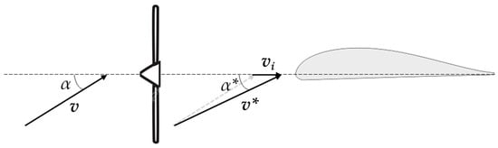
This section provides a focus on the high-lift DP, hence the research related to the potential advantages of DP applications to increase maximum lift coefficient 𝐶𝐿 𝑚𝑎𝑥 and to reduce take-off and landing required field length. Specifically, the literature regarding different aircraft categories is investigated, ranging from general aviation to commuter and regional aircraft. The high-lift effect of DP on a wing is twofold; on the one hand, it allows for a local increase in the dynamic pressure acting on the airfoil, and on the other hand it locally reduces the angle of attack of the airfoils, delaying the stall to higher angles. Both effects can be qualitatively explained by considering the simpler case of a 2D airfoil. Considering the airfoil depicted in Figure 1, the angle of attack is equal to α, and its relative wind speed is v. The presence of a propeller upstream of the airfoil superimposes the following: (i) an airflow at velocity 𝑣𝑖 (named induced velocity), which increases the actual velocity 𝑣∗ of the airflow investing the airfoil; (ii) a reduction in the angle of attack 𝛼∗, according to Equations (5) and (6):
Figure 1. Effect of induced velocity on the angle of attack of an airfoil.
Equation (2) shows that the actual velocity of the air investing the airfoil depends on the ratio 𝑣𝑖/𝑣: the higher the 𝑣𝑖/𝑣, the larger the 𝑣∗. The related increment of local dynamic pressure induced by the thruster in the downstream region can be defined as the blowing effect. Increasing 𝑣𝑖/𝑣 also introduces a reduction in the airfoil angle of attack, as Equation (2) shows.
The lift 𝑙∗ produced by the airfoil is calculated according to Equation (7)
where 𝐶∗𝑙 è is the airfoil lift coefficient associated with the airflow at speed 𝑣∗, 𝜌 is the air density, and 𝑐 is the airfoil chord. By exploiting the well-established linear relationship between the lift coefficient and the angle of attack and substituting in Equation (7) for Equations (5) and (6), the following result is obtained:
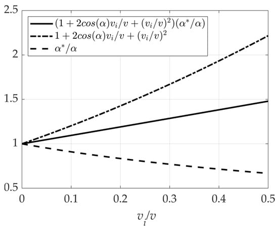
where 𝐶𝑙 is the lift coefficient associated with the airflow at speed v. This result shows that there are two corrective factors to the airfoil lift: the factor resulting from Equation (1), i.e., the term 1+2cos𝛼𝑣𝑖𝑣+(𝑣𝑖/𝑣)2, is amplifying, while the factor resulting from Equation (2), i.e., 𝛼∗𝛼, is attenuating. However, despite the two opposing effects, it can be seen from Figure 2 that the resulting trend on the lift coefficient is of amplification, i.e., there is an increase in the lift coefficient.
Figure 2. Trends of the corrective factors varying the ratio 𝑣𝑖/𝑣 for 𝛼 = 15°.
Two clarifications need to be made: (i) the result obtained here is true in the linear part of the 𝐶𝑙-α curve of the airfoil, whereas in proximity of the stall condition the relationship is not accurate; however, it has been used to obtain a qualitative description on the effect of propeller blowing; (ii) the result obtained so far on the 2D airfoil are useful to qualitatively understand the blowing effects on the wing, but it does not allow an estimate of the stall behavior of a finite wing, since the stall phenomenon is very complex and three-dimensional, and it needs advanced simulation tools (CFD or experimental tests). In the following, studies of high-lift DP applications to aircraft designs are discussed.
In ref.
[29] a numerical campaign is carried out to characterise the benefits of DP in take-off conditions for a regional aircraft. To do this, a portion of an infinite rectangular wing with a single propeller is simulated by imposing periodic conditions at the boundary of the domain. The wing does not present any variation in chord length and twist, and a single slotted flap is considered a high-lift system; the propeller is located in the center of the wingspan with the forward offset with respect to the leading edge. The numerical analysis is based on an in-house high-fidelity code which solves RANS equations and models the propeller effect via the disk actuator theory. The parameters set up for the simulation are standard sea level condition and an M equal to 0.176. The numerical campaign investigates the effect of thrust and propeller diameter.
Ref.
[29] critically discusses the effect of propeller diameter and disk loading, but there is no investigation about the relative position between the propeller and wing; this aspect is investigated in ref.
[30]. A rectangular infinite wing is considered, standard sea level conditions and speed equal to 35 m/s are assumed, and propeller diameter and angular speed are kept constant and equal to 0.33 m and 8045 rpm, respectively. A fowler flap is selected as high-lift technology, extended to 30% of the wing chord. In addition to the wing-propeller relative position, the paper also investigates the effect of tilting the propeller downward; RANS simulations are used for the numerical assessment. The effective lifting coefficient
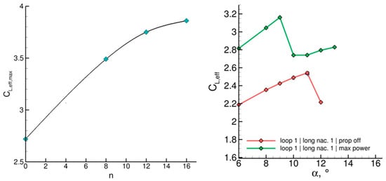
𝐶𝐿,𝑒𝑓𝑓is defined as the lift coefficient generated by the wing and the component of the propeller thrust in the direction perpendicular to the airflow. The results of 3 (left) highlight that the vertical position Z of the propeller (normalized with the radius R) has a significant impact on the 𝐶𝐿,𝑒𝑓𝑓 compared to the isolated case at the same angle of attack(grey lines); namely, the isolated cases refer to the simulations carried out with isolated propeller and wing, without considering any mutual aerodynamic interaction. 3 (center) reports the correlation between the horizontal position of the propeller X (normalized with the wing chord c) and 𝐶𝐿,𝑒𝑓𝑓, highlighting that the horizontal wing–propeller relative position does not significantly impact the lift coefficient. In fact, for angle of attack values close to 6°, the 𝐶𝐿,𝑒𝑓𝑓 is constant for X varying from −0.5 c to −0.3 c, whereas if the angle of attack increases up to 14° an increment of 2.7% is obtained moving the propeller in the horizontal direction from −0.2 c to −0.5 c. The same chart shows that there is a correlation between X and Z in order to maximize the 𝐶𝐿,𝑒𝑓𝑓. Lastly, the effects of tilt angle θ of the propeller on 𝐶𝐿,𝑒𝑓𝑓
are depicted in 3 (right). The physical implications of a downward tilting of the propeller are (i) the actual angle of attack of the wing increases and (ii) the component of the thrust perpendicular to the undisturbed airflow raises. These two effects generate larger lift coefficients; however, attention must be paid to the stall condition, which can be anticipated for high tilting angles. This aspect is depicted by the huge drop in the lift coefficient with a θ equal to 20°.
3. 𝐶𝐿,𝑒𝑓𝑓 curve varying propeller vertical position (
left), horizontal position (
center) and tilting angle (
right). Image adapted from
[30].
Another interesting work on numerical and experimental investigations of wing–propeller interaction is proposed in ref.
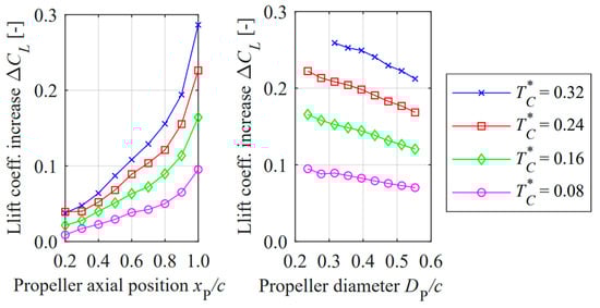
[31]. In this case, the propeller is installed in an overwing layout to comply with ground clearance constraint and to provide a shielding effect to reduce noise. The experimental set-up consists of a rectangular wing with a fowler flap of 30% chord length and a deflection of 23°. The propeller, positioned in the center of the wing, and aligned with the direction of the undisturbed flow, is made of four blades with a diameter of 0.237 m. The experimental campaign was useful to provide reference and validation to the numerical simulations. For the high-lift condition, the effect of the propeller advance ratio (i.e., the ratio of the airflow speed and the product of the angular velocity of the propeller and the propeller diameter) has also been investigated; the results highlight that lower values of advance ratio correspond to higher values of the lift coefficient. As a second step, numerical analyses have been performed to assess two interaction effects on the lift coefficient: (i) the longitudinal position of the overwing propeller and (ii) the propeller diameter. The results, reported in
4 (left), show that the closer the propeller is to the wing trailing edge, the higher the lift coefficient. This is associated with the suction effect induced by the propeller, which generates a high local speed in the airfoil upper chamber and, consequently, an increase in the lift. This effect is enhanced if the propeller provides high thrust, as shown for the curves at different thrust coefficients
𝑇∗𝐶, i.e., the ratio of the thrust generated by the propeller on the product of the dynamic pressure and the wing area. Regarding the effect of the propeller diameter, the results show that the reduction of propeller diameter is beneficial to the lift coefficient. This result highlights that, in the case of an over the wing DP, a large number of small propellers can positively affect the lift coefficient; nevertheless, if the thrust is fixed, the reduction in propeller diameter is limited by the tip Mach number. In fact, to keep constant thrust, if the radius of the propeller is reduced, the rotational speed must increase (e.g., a reduction of 5% in propeller diameter causes an increase of 10% in rotational speed, assuming a constant propeller thrust coefficient); therefore, the Mach of the propeller tip raises, and this effect is more evident for larger values of 𝑇∗𝐶.
4. Lift coefficient increases due to propeller axial position (
left) and diameter (
right). Image adapted from
[31].
Ref.
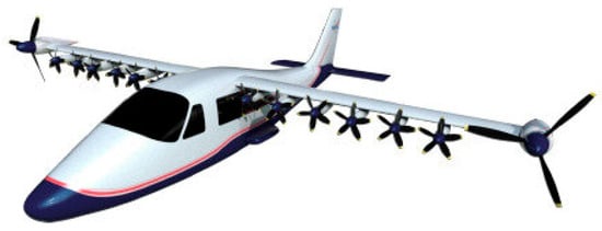
[32] describes the impact of DEP on the
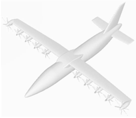
𝐶𝐿 𝑚𝑎𝑥 of a full-electric commuter aircraft powered by fuel cells. The proposed aircraft configuration exhibits distributed propellers along the wingspan and two wingtip propellers, as shown in
5; all the propellers are driven by electric motors.
5. Artistic representation of the aircraft configuration analysed in ref.
[32].
The wing-tip propeller generates a wake flow field to reduce the intensity of the wing-tip vortex and, consequently, the induced drag of the aircraft. The remaining distributed propellers, four for each half wing, are integrated to enhance the aircraft’s high-lift performance.
After the conceptual assessment, ref.
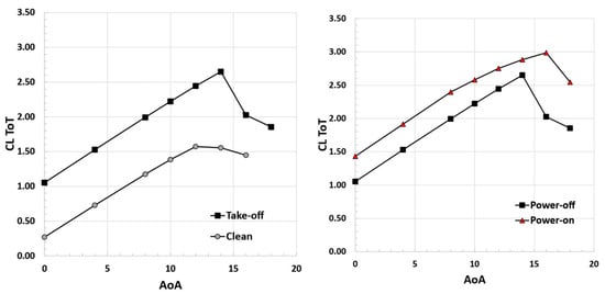
[32] provides the study of the DEP effects on high-lift performance of the aircraft. As a first step, CFD analyses have been carried out to compute the lift curve of the wing with high-lift system deployed; the aircraft, without DEP active, achieves
𝐶𝐿 𝑚𝑎𝑥= 2.65 in the take-off (TO) phase. The same analyses were repeated by simulating the DEP effect by means of the virtual disk model; this is a method, developed to be integrated in CFD analysis, that efficiently simulates the effect of propellers on fluid flow without directly modeling its geometry
[33]. The main outcomes are (i) an increase in
𝐶𝐿 𝑚𝑎𝑥 for the take-off phase equal to 13.2% and (ii) an increase in stall angle of attack by 2°; these results are shown in
6.
6. 𝐶𝐿-
α curve with DEP off (
left) and on (
right) during take-off. Image adapted from
[32].
The predicted increase in the 𝐶𝐿 𝑚𝑎𝑥 due to the DEP effect allows for an estimated reduction in the take-off length of 7% with respect to the case without DEP. It emerges, however, that the design of DEP and high-lift system should be coupled to properly assess their interaction and maximize the effect on 𝐶𝐿 𝑚𝑎𝑥.
In the context of regional transport aircraft, the European project IMOTHEP aims at investigating hybrid-electric powertrains coupled with advanced propulsive concepts, such as the DP. In ref.
[34] the effects on the maximum lift coefficient of the number of propellers and their relative position to the wing are investigated on two different aircraft. Regarding the high-lift system, a single slotted flap is considered, the propellers are distributed along the wingspan with a clearance (i.e., the distance between the tips of two consecutive propellers) equal to 18% of the propeller diameter. Several simulations based on RANS coupled with the actuator disk are carried out varying the number of the propellers between two and eight (for each half wing). For each investigated case, the propeller diameter has been increased as much as possible in order to fulfil the clearance between the propeller and not exceed a maximum pre-defined value of 4 m. Regarding the propeller position, similar results to that proposed in ref.
[30], are obtained; in particular, a position of the propeller below the wing (up to 0.4 m) maximizes the increment of the lift coefficient for a high angle of attack. The effect of increasing the number of propellers on the
𝐶𝐿,𝑒𝑓𝑓 is reported in
7 (left), showing that the maximum lift coefficient increases as the number of propellers raises. This result is consistent with those proposed in ref.
[29] and is attributable to the fact that a higher number of propellers involves single units with smaller diameters. In this case, the wing is blown by a more uniform flow (than in the case of two propellers), enhancing the wing lift capability. The effects of the
𝐶𝐿,𝑒𝑓𝑓 variation with respect to the power-off condition has also been evaluated for the case of four propellers; the results, depicted in
7 (right), show an increase of 0.64 on the maximum lift coefficient.
7. 𝐶𝐿,𝑒𝑓𝑓 increase varying the number of propellers (
left) and C
L-α curve for power-off and power-on condition (
right). Image adapted from
[34].
In the category of general aviation, NASA has proposed a large project, named SCEPTOR (Scalable Convergent Electric Propulsion Technology and Operations Research), which aims at developing technologies that show the effectiveness of DEP to reduce emissions and cost and to increase the aircraft overall efficiency (i.e., lift-to-drag ratio and propulsive efficiency)
[35][36]. Through the use of electric propulsion, the efficiency of the propulsive chain is improved, and the high aspect ratio wing design combined with DEP and wing-tip propellers, allow for a reduction in the energy required to fly. A sketch of the SCEPTOR aircraft is proposed in
8.
8. Sketch of the flight test demonstrator of SCEPTOR project. Image adapted from
[35].
The general study aims to investigate and exploit the beneficial effects of DP on high-lift performance, on wing design and on overall aircraft mission performance; furthermore, the project aims to investigate noise emission reductions, improvements in flight safety and the certification process for an aircraft using DEP. As discussed in the following, in this context NASA provided several studies on the characterisation of this concept. Ref.
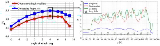
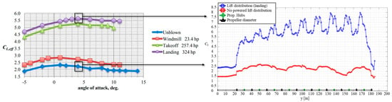
[37] investigates the DP-wing aerodynamics during take-off and landing phases via numerical simulations. DP consists of 18 propellers (9 per half wing) mounted on the leading edge and with the axis parallel to the free stream; the wing presents a fowler flap along the entire wingspan, with a chord extension of 30% of the wing chord and can deflect up to 40°. As a preliminary analysis, the effect of co-rotating and contra-rotating near-propellers has been investigated, focusing on the effects on the lift distribution and lift coefficient. In the contra-rotating scheme, propellers alternate their rotation such that if a propeller rotates clockwise, adjacent propellers rotate anti-clockwise. The simulations have been carried out considering a freestream velocity of 118 km/h. The results highlight that the co-rotating solution exhibits a higher lift coefficient, as depicted in
9 (left), due to a more homogeneous lift distribution. In fact, as shown in
9 (right), in the case of counter-rotating propellers the alternate rotation introduces huge variations in the lift distribution where the peaks (valleys) are related to the upwash (downwash) generated by two adjacent propellers. These effects on the lift distribution introduce a general reduction in the lift with respect to the co-rotating scheme; hence, the co-rotating DP is suggested as the concept to be developed.
9. Effect of co-rotating and contra-rotating DP on lift coefficient (
left) and lift distribution (
right). Image adapted from
[37].
The effects of the co-rotating scheme on the lift coefficient compared to the unblown case are then investigated varying the DP thrust. The simulation results show that increments of 𝐶𝐿,𝑒𝑓𝑓
up to 2.4 can be attained if propellers generate their maximum thrust, as reported in 10 (left). The blowing effect of the DP is well highlighted in 10 (right), which shows a huge increment of the spanwise local lift coefficient with respect to the unblown case. According to the authors, the increment of lift coefficient allows a reduction in wing area of 42%, with a positive consequence on friction drag reduction and on increases of lift-to-drag ratio in cruise condition.
10. 𝐶𝐿,𝑒𝑓𝑓-
α curve (
left) and lift distribution (
right) of powered and unpowered wing with flap deflection of 40°. Image adapted from
[37].
An assessment of the effect of rotor failures on the high-lift performance has been performed and discussed in
[37]. The results showed that high reductions of
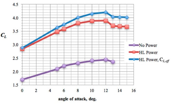
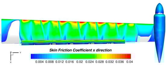
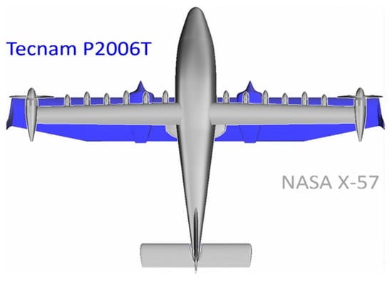
𝐶𝐿,𝑒𝑓𝑓occur in the case of multiple failures of propellers and adversely affect the high-lift performance; hence, a comprehensive failure analysis and off-design scenarios must be taken into account when sizing the DP high-lift system of an aircraft. Another in-depth focus on DP low-speed performance was provided in ref. [38], where a numerical analysis of DEP mounted on the wing of the NASA X-57, a retrofit of the Tecnam P2006T aircraft, is carried out. The concept has 12 high-lift propellers on a high aspect ratio wing with a flap that can be deflected up to 30°. Simulations have been computed by solving RANS coupled with an actuator disk to model the effect of the propellers; a freestream speed of 108 km/h and standard sea level conditions have been considered. The results, depicted in 11 (left), show that DEP can increase 𝐶𝐿 by 1.4 if compared to the solution with DEP not activated; the effect is even larger if the contribution of the propeller thrust is considered (𝐶𝐿,𝑒𝑓𝑓): in this case the increment is of about 1.8. Lift coefficient increases up to an angle of attack close to 12°, then the flow separation occurs in the inboard and outboard region of the wing, as depicted in 12.
11. CL-
α curve of the NASA X-57. Image adapted from
[38].
12. Evidence of the separation area (grey colored) for
α = 13°. Image adapted from
[38].
Low-speed performance of the Cirrus SR22 aircraft retrofitted with DEP has been evaluated in ref.
[39]. Cirrus SR22 is a general aviation aircraft with an entry into service in the early 2000s, whereas the previously described Tecnam P2006T is a more recent aircraft. The distributed propellers, driven by electric motors and batteries, are placed on the leading edge of the wing; the number of propellers is considered variable and equal to 2
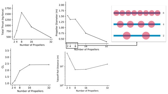
N, with N = {1,2,3,4,5}. A constrained optimization procedure was set to minimize the rolling take-off run length; among the constraints, the most relevant are related to the cruise range and the tip Mach number of propellers (limited to 0.8). Propeller aerodynamic performance is evaluated by using blade element momentum (BEM) theory, whereas propeller–wing interaction is modeled using the VLM (Vortex Lattice Method). The results showed that the number of propellers strongly influences the take-off performance of the aircraft; in particular, increasing the number of propellers up to 16 can significantly reduce the take-off rolling runway (
13 (bottom right)). This occurs because the number of propellers significantly impacts the amount of generated thrust and the lift coefficient (blowing effect). Regarding the first point, the aircraft total thrust increases if the number of propellers raises to eight (
13 (top left)); this happens because, in this study, propeller tips cannot overlap; therefore, the diameter is constrained to the wingspan. As depicted in
13 (top right), the propeller diameter reduces and the total disk area increases as the number of propellers increases, leading to the generation of a larger thrust than with two propellers. As the number of propellers increases more than eight, the wingspan constraint implies a reduction in propellers diameter, hence not allowing for a further increase in thrust. The increase of the number of propellers generates a beneficial effect in terms of the maximum lift coefficient (
13 (bottom left)), which may be larger of a factor of 2.2 than the two propellers. It is worth noting that lift coefficient curves increase until the number of propellers reaches 16, and then flattens for higher numbers of propellers (>16); this is related to two effects: the reduction in the propeller diameter, which implies lower propeller diameter–chord ratios, and the reduction in thrust (see
13 (top left)). The combination of the two effects causes a less intense blowing effect that limits the extra lift.
13. Effect of number of propellers on thrust (
top left), propeller diameter (
top right), aircraft lift coefficient (
bottom left) and take-off rolling distance (
bottom right). Image adapted from
[39].
In ref.
[40], the methodology proposed in
[39] was applied on the NASA-X57 aircraft, considering the entire take-off run and introducing a noise constraint in the optimization procedure to assess its effect on take-off performance; noise is modeled according to the method proposed in ref.
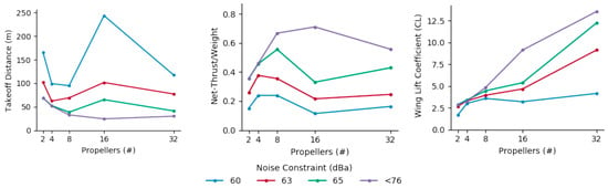
[41]. The main results are reported in
14 and show the effect of noise constraints on take-off distance (
14 (left)), propeller thrust (
14 (center)) and lift coefficient (
14 (right)). The main physical effect of the noise constraints is a limit on the Mach at the tip of the propeller; this limit imposes a reduction in propeller angular speed and, consequently, in propeller thrust. Hence, by imposing stricter noise constraints, i.e., lower noise emissions, implies a lower thrust; this leads to a lower induced speed on the wing and, hence, an attenuation of the blowing effect that reduces the lift coefficient. The two combined effects reflect an increase in take-off field length. The penalizing effect on the lift coefficient, as the noise constraint becomes stricter, is more pronounced for a high number of propellers (≥8); in these cases, the reduction in propeller diameter leads to increases in angular speed to supply an equivalent level of thrust, and hence, the tip propeller speed matches the earlier constraint on tip Mach.
14. Take-off field length (
left), thrust-to-weight ratio (
center) and lift coefficient (
right) vs. number of propellers. Image adapted from
[40].
4. DP for Improvement of Lift-to-Drag Ratio
The wing design has always been a compromise between the low-speed and high-speed performance and requirements, leading to a less-than-optimal wing design. The presence of DP may, in addition to the previously discussed increase in aircraft high-lift capability, enable a reduction in the wing wetted surface; this could represent a potential performance benefit during the high-speed phase, theoretically leading to higher lift-to-drag ratio L/D and, hence, to lower energy required to fly. The topic has been investigated in the available literature, as discussed in the following. In particular, the relevant references are carefully reviewed considering regional and short–medium range and general aviation DP applications.
Ref.
[42] describes the effect of DEP on overall aircraft performance, as L/D and block fuel consumption. This aspect has been investigated by designing three different regional aircraft which mount 2, 6 and 12 propellers, respectively. The TLARs define a range of 1000 nm, a cruise Mach and an altitude of 0.55 and 27,000 ft, respectively, and a number of passengers equal to 70. The propellers are powered by a turboelectric powertrain; the thermal turboshafts and generators are located in the upper part of the fuselage and are symmetrical with respect to the wing position, whereas the electric motors are positioned in the wing nacelles. The reference baseline to perform comparisons is considered the 2-propeller configuration.
15 reports an artistic representation of the aircraft previously described.
15. View of the three aircraft (
left) and powertrain integration scheme (
right). Image adapted from
[42].
A multidisciplinary design and optimization framework, involving propulsive, aerodynamics and system sizing, and the related performance assessment, is used to develop the three configurations; the wing–propeller interaction is evaluated by means of RANS solver coupled with the actuator disk to model the action of the propellers. Table 3 reports the main results of the design process; some interesting outcomes for the three aircraft configuration can be discussed. First, the DP introduces significant reductions in the vertical tail surface; indeed, maintaining a vertical tail sizing requirement for each configuration based on the one engine inoperative scenario, the DP with 12 propellers allows for a reduction of 52% of the tail surface, and the DP with 6 propellers allows for a reduction of 24.6% of the tail surface. Furthermore, an increase in 𝐶𝐿 𝑚𝑎𝑥
equal to 5.5% and 11%, and an increase in W/S equal to 5.2% and 10.6%, is estimated for the DP with 6 and 12 propellers, respectively. The increment of W/S allows for a wing area reduction of 7.9% and 12.6% for the 6 propeller and 12 propeller configurations, respectively. Notwithstanding, these significant effects on the reduction of overall aircraft friction drag, in the evaluations made in ref.
[42], do not lead to overall benefits in L/D resulting from the presence of DP; hence, the installation of the distributed propulsion also introduces drag increases that may undermine the beneficial effect in terms of wing design. In general, the slight benefit obtained in terms of block fuel for the DP configurations is more attributable to reductions in powertrain mass and MTOW than to an actual aerodynamic benefit.
A subsequent focus on this topic, with a more in-depth discussion of the lift-to-drag ratio of the aircraft is provided in ref.
[43]; the layout with 12 propellers is considered. The numerical assessments are based on RANS equations coupled with the actuator disk model; the simulations focus on the wing and propeller only, excluding other aircraft components, such as the fuselage or the vertical tail. The rationale of this choice is to simulate only the wing–propeller interaction. The results show that the baseline configuration with two propellers presents an L/D = 17.73, while the configuration with 12 propellers exhibits a lower value of 17.36. This result is related to the wing–propeller interaction, which causes a non-uniform load repartition on the propeller: the upwash occurring in the proximity of the leading edge of the wing, leads to an asymmetric load on the propeller area according to the direction of the propeller rotation. This negatively affects the wing lift distribution, leading to a slight increase in the wing drag. In a second step, to improve the L/D the DP were shifted towards the wingtip; this resulted in an increase in L/D of 0.11 compared to the previous case, due to a beneficial effect on the wingtip vortex. Finally, to further improve the DP design, the thrust of each individual propeller was optimized to reduce the required power by acting on individual pitch angles. This resulted in a non-homogeneous thrust repartition where the wing-tip propeller generates the highest thrust, among the other propellers, which, in turn, reduces the intensity of the wing-tip vortex and further increases L/D of 0.24, to gain a value comparable to that of the two-propeller baseline. Overall, the DP, hence, does not provide a significant benefit on aircraft cruise aerodynamic performance in this case. The results obtained in ref.
[43], however, are not in contrast with the theory because in this case the wing was not re-designed together with the DP but was only retrofitted with this propulsion system. A redesign of the wing, taking into account the extra lift provided by the DP, could instead lead to smaller wing wetted area, contributing to a drag reduction.
A more comprehensive performance analysis is carried out in ref.
[44], which presents a multidisciplinary design optimization to assess the performance of a hybrid-electric aircraft with electric-driven distributed fans. Specifically, the case study is a 150 passenger transport aircraft, which mounts a hybrid-electric powertrain with a serial architecture. It has two turboshafts (coupled with the generators) located in the aft fuselage, and the battery packs are hosted in the aircraft fuselage. DEP is positioned in the upper part of the wing, resembling the over-the-wing concept. A sketch of the aircraft and a scheme of the powertrain are reported in
16.
16. Aircraft view (
left) and powertrain scheme (
right). Image adapted from
[44].
The MDO framework evaluates several aspects, geometry, aerodynamics, structural mass and system mass, which are computed via low-fidelity models based on statistical and/or semi empirical equations which are well-established in the literature. Several MDO analyses have been carried out varying the number of fans 𝑛𝑓
= {16, 32, 48} and the range R = {600, 900, 1200, 1500} nm, and considering fuel and energy consumption as figures of merit. To assess the benefit of DP, the optimum configurations are compared with a baseline thermal configuration designed according to the same TLARs. The results highlight that hybrid-electric configurations can reduce fuel consumption or required energy only if a limited range is considered. The maximum range compatible with any gain in fuel or energy consumption, named breakeven range, depends on 𝑛𝑓, it emerges that DP does not improve L/D and, overall, a reduction in fuel consumption can be achieved. Regarding the effect on L/D, it can be noted that the best configuration has 16 fans, since it exhibits the lowest wetted surface, but L/D is still lower than the baseline configuration. Looking at the fuel consumption, it can be noted that a reduction of up to 18% can be achieved in the case of 32 fans for the 600 nm range. This result is more related to the presence of batteries onboard, which generate sufficient energy to reduce fuel consumption, than to aspects related to DEP.
In ref.
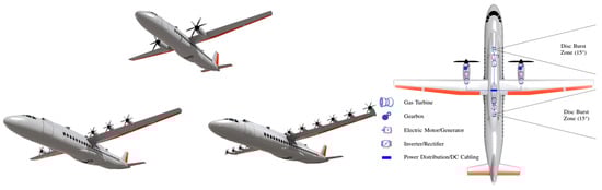
[45] a conceptual design methodology which integrates the aero-propulsive interaction between DP and wing is proposed. The methodology exploits the well-known theory of propellers and assesses the effects of the DP integration in the design process of a regional aircraft, specifically regarding possible impacts on the powertrain sizing matching chart, the aircraft weight and the mission performance. Two different regional aircraft are designed, one mounting a turboelectric powertrain and another with a serial one. Both aircraft are compared with a thermal baseline designed according to the same TLARs (i.e., range of 825 nm and 78 passengers); a sketch of the three configurations is depicted in
17. Regarding the first point, the improvement of low-speed aircraft performance (in terms of lift coefficient) due to DP allows the ability to enlarge the design space and select a higher wing loading (W/S); this, in turn, has a positive effect on the wing area, which is reduced by 18.3% and 36.2% for serial and turboelectric configuration, respectively. The reduction of the wetted area has a direct effect on aircraft L/D (in cruise condition), which rises by 5.1% and 5.7% for serial and turboelectric configurations, respectively. The weight of the hybrid-electric aircraft is higher than the thermal configuration due to the penalties introduced by the electric components; this aspect is more relevant for the serial configuration which holds a battery on board; a heavy component with very low specific energy (500 Wh/kg in this case study). This increment of weight is the main cause of the increase in fuel consumption, which is only partially limited by the better L/D of DP configurations, but not sufficient to introduce an overall benefit.
17. Thermal baseline configuration (
left), serial configuration (
center) and turboelectric (
right). Image adapted from
[45].
Moving to general aviation cruise DP applications, it is useful to recall some results of the aforementioned SCEPTOR project; specifically, ref.
[46] discusses on the overall performance of the DP retrofitted Tecnam P2006T. The retrofitting strategy provides (i) distributed propellers along the leading edge of the wing to improve the high-lift capability and (ii) larger cruise propellers located on the wingtips to generate the cruise requested thrust and to lower induced drag by reducing the intensity of the wingtip vortex. The energy source is a battery pack installed in the aircraft fuselage which powers the electric motors directly connected to the propellers. A comprehensive multidisciplinary aircraft design led to the DP-retrofitted configuration, named X-57, whose features are sketched in
18. The wing area reduction provided by the integration of the DP propulsion system is numerically and graphically evident.
18. Wing planform comparison between X-57 and P2006T. Image adapted from
[46].
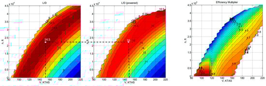
The L/D evaluated in cruise for the powered and unpowered case is depicted in 18 (left/center). The effect of wingtip propellers for several combinations of speed and altitude shows that an improvement of L/D in the range 5–10% is attainable. More significantly, the comparison with the Tecnam P2006T is shown in 18 (right), taking as a figure of comparison the efficiency multiplier; this has been defined as the ratio between the energy requested by the NASA X-57 and by the Tecnam P2006T to accomplish the mission (computed as the integral, over the flight time, of the product between the aircraft speed and the thrust supplied by the propellers). The results highlight that the retrofitted aircraft is able to reduce energy consumption by up to five times. This result is mainly attributable to the higher L/D of the retrofitted configuration which, even for weights of 130 kg higher than the reference configuration, can reduce the energy needed to accomplish the flight. Hence, this result is the opposite of what was found for the regional aircraft DP applications.
18. Effect of wing-tip propellers on L/D (
left/
center) and efficiency multiplier map comparison with the baseline (
right). Image adapted from
[46].
A similar approach has been adopted in ref.
[47], which describes the conceptual design and optimization of a full-electric light aircraft which resembles the configuration of NASA X-57. The examined fixed-wing DEP aircraft incorporates propellers positioned on both the leading edge of the wing and the wingtip. For the low-order analysis, OpenVSP has been chosen as the design tool, employing the VLM to model the wing aerodynamics and treating the propellers as actuator disks. The methodology is composed of the following steps: (i) design of the wing via optimization algorithm to maximize L/D at a 0° angle of attack and working on six design variables, namely, root chord, tip chord, wingspan, twist angle, incidence angle and dihedral angle; (ii) design choice to reduce the reference wing surface by 15% due to the potential lift increasing effect of DP; (iii) verification via CFD analysis that the wing calculated at the second step exhibits higher L/D than the wing at the first step; (iv) optimization of the distributed propellers and wing-tip propeller; diameters and advance ratio are the design variables and the objective functions are the lift coefficient at take-off and the aero-propulsive efficiency; and (v) finally, a sensitivity analysis of the number of distributed propellers coupled with the nacelle is performed via CFD analysis. The main objective of this latter step is to maximize aircraft L/D in cruise. Following these steps, a configuration with 10 distributed propellers has been selected. Optimal L/D is computed via CFD analyses in order to assess the potential gain of this configuration with respect to the configuration designed at step (i); the results have highlighted an L/D improvement of 1.7% with respect to the configuration designed at first step.
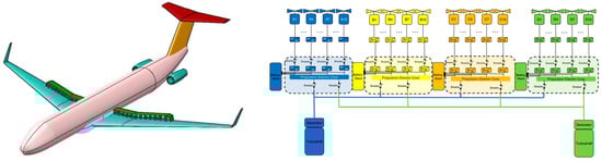
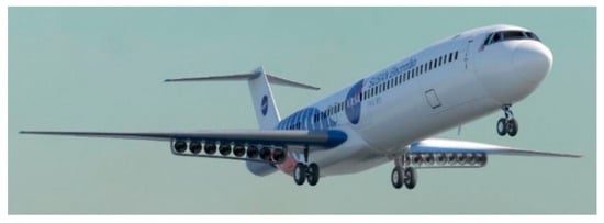
More recent concepts continue to explore the potential benefits of distributed propulsion. NASA is currently exploring innovative alternatives aimed at reducing the number of hydrocarbon fuel-consuming and power-generating engines from two to one. An example of such a concept in development is the Subsonic Single Aft Engine (SUSAN) Electrofan
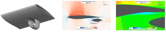
[48], designed to achieve a 20 MW class Electric Aircraft Propulsion (EAP) system, contributing to the aircraft’s electrification and fuel consumption reduction. The SUSAN Electrofan features a series/parallel partial hybrid-electric powertrain, utilizing a fuel-burning aft-fuselage propulsor connected to Megawatt-class power generators that support wing-mounted electric propulsors (see
19). The aft fuselage turbofan incorporates BLI (see
Section 4) and is designed to deliver 35% of the total aircraft thrust, while wing propulsors adopt under wing distributed electric propulsion (DEP) configurations, which is responsible for the remaining 65% of aircraft thrust. The current version of the SUSAN Electrofan has sixteen low FPR ducted fans distributed evenly across both wings, providing the propulsion system with the benefit of an ultra-high overall bypass ratio. The DEP systems each adopt an integrated mail-slot nacelle configuration that helps to reduce the wetted area associated with the inclusion of many small individual propulsors. Preliminary low-order multidisciplinary design optimization evaluations suggest that, compared to a reference aircraft based on 2020 technology levels with the Boeing 737-8 as a reference, the SUSAN Electrofan could potentially achieve an 11.1% reduction in block fuel for a 750 nm mission
[48][49].
19. Representation of SUSAN transport aircraft concept. Image adapted from
[48].
However, the configuration is still under extensive investigation, and different developments and updates are to be expected. The arrangement of the ducted fans has been the subject of numerous architectural analyses, by means of numerical aerodynamic simulations. Specifically, as discussed in detail in ref.
[50], a comparison between overwing and underwing installed ducted fans was conducted. Specifically, in both cases the DPs are mounted near the trailing edge, in the suction and pressure areas of the wing, respectively;
20 (left) and
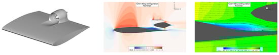
21 (left) represent the two installations, showing a single propulsive unit. The main advantage of the overwing layout lies in the fact that the suction provided by the fans increases the overall suction of the wing, thus providing increases in lift and energisation of the boundary layer, preventing its separation. However, for applications in the transonic flight, such a configuration could result in flow accelerations that cause an onset of shockwaves that can compromise the quality of the fans’ ingested flow. The preliminary CFD analyses proposed in ref.
[50] specifically highlight these effects, as reported in
20 (center) (shock wave on the suction side) and
20 (right) (flow separation pocket in the inlet region). A further potential disadvantage of overwing assembly is related to the increase in the local pressure due to the presence of the propulsor, and the fostering of turbulent boundary layer transition, which prevents the implementation of natural laminar flow technologies to reduce drag.
20. SUSAN overwing ducted fans: 3D view (
left), center plane Mach contours (
center), center plane velocity contours (
right). Image adapted from
[50].
21. SUSAN underwing ducted fans: 3D view (
left), center plane Mach contours (
center), center plane velocity contours (
right). Image adapted from
[50].
The underwing configuration, on the other hand, is beneficial specifically in removing or mitigating the unfavourable aspects of the overwing assembly at the expense, however, of a penalized pressure field in the underside of the wing due to fan suction; this aspect reduces the wing’s lifting capacity. This feature must be carefully taken into account when designing the wing. 21 (center) shows that the shock wave in the suction area is more attenuated and that there is no flow separation in this area of the wing. In addition, the separation pocket at the fan inlet due to the adverse pressure gradient is much smaller than in the previous case, as depicted in 21 (right).
4. Multiple Discrete Propulsive Units
In the previous sections researchers have discussed the characteristics, performance and aircraft integrations of the literature applications of DP concepts, i.e., the one with fans/propellers distributed along the span, with airframe-synergic aerodynamic behaviour. In this section, instead, researchers will briefly discuss the multiple discrete engines, a definition that refers to the use of a large number of propulsive units sized mainly to generate the thrust required to fly. The use of such a solution has been used in the past for reasons related to the achievable maximum power of the state-of-the-art engines and/or to large aircraft thrust requirements. An example of an aircraft using such arrangement was the Antonov An-225 Mriya
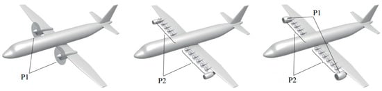
[51], which had three engines on each half wing. To exploit this concept to achieve other benefits than the simple accomplishment of required thrust, novel configurations with a large number of discrete engines have been proposed in the literature. Ref.
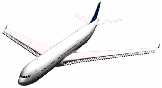
[19] aims at assessing the effects of full-thermal DP allocating several podded engines under the wing, as depicted in
22. The effects of thrust subdivision on engine performance (SFC), engine weight, nacelle weight and drag, bending relief and vertical tail sizing have been investigated. Regarding SFC, it has been demonstrated that the overall thermal efficiency reduces and, consequently, SFC increases. The same occurs for the engine weight, specifically; even if the weight of the engine’s main components is reduced, other systems are not scalable, and this causes an increase in overall propulsion weight. Nacelle drag scale nonlinearly, so an excess of wetted surface is expected, causing a lower L/D of the aircraft. Bending relief is the static stress reduction generated by weight distributed along the wingspan; the proposed DP allows for mitigation of the stress induced by lift. Finally, thanks to thrust vectoring, it is possible to reduce vertical tail size. All these aspects have been inserted in a conceptual design methodology aiming at assessing the benefits of DP on a short–medium range aircraft. The results highlight that the detrimental effect introduced by the SFC increase overwhelms all the partial beneficial effects introduced by DP; in fact, the aircraft with DP is heavier and the block fuel consumption is higher than a reference conventional benchmark with two turbofans.
22. Tube-and-wing with full-thermal multiple discrete engines. Image adapted from
[19].
In ref.
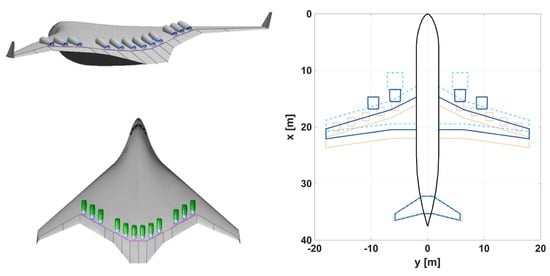
[52] a BWB integrating 12 thermal propulsive units is presented to benefit from both the potential high lift-to-drag ratio of the BWB and from the integration of the engines into its structure to reach a noise shielding by configuration. However, as demonstrated in ref.
[23], splitting the thrust over multiple thermal propulsion units results in the installation of smaller engines, which show lower efficiency and higher specific consumption
[19]. Hence, the features of thermal aero engines seem to be not suitable for this application, as reducing their dimension leads to a loss of performance, reflected in an overall higher fuel consumption; furthermore, a larger number of thermal engines unnecessarily increases the time and the cost of standard and non-standard maintenance operations. On the other hand, these unfavorable characteristics are not present for electric motors, which do not show any dependence of their efficiency with the size and require less maintenance than the corresponding thermal engines
[53]. Thus, multiple discrete electric motor applications have been considered for integration on full-electric aircraft, as investigated in
[54]; even if in this research the optimum number of electric motors does not exceed four, the possibility of designing a next generation electric aircraft with a larger number of discrete propulsive units remains open. A schematic of refs.
[52][54] is reported in
23.
23. BWB with 12 thermal engine (
left) and tube-and-wing with DP (
right). Images adapted from
[52][54].
5. Experimental Assessment: Scaled Demonstrators
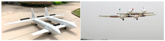
To conclude the DP general review, it is also worth mentioning that some experimental studies aimed at assessing the aerodynamic and aeromechanical characteristics of distributed propulsion aircraft by means of scaled flying models. In this regard, the activities described in ref.
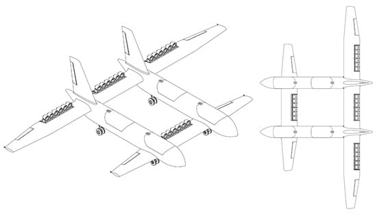
[55] are of particular note and involve design and flight testing activities on a flying model with short take-off and landing (STOL) features and equipped with DEP; specifically, the experimental activities, both on the ground and in flight, of an aircraft with a mass of 40 kg having a tandem wing configuration and twin-fuselage are described. A view of the aircraft developed in ref.
[55] is proposed in
24.
24. Views of the flying model DEP demonstrator. Image adapted from
[56].
The tandem lifting architecture consists of two wings staggered both vertically and horizontally and provides advantages in terms of aerodynamics, i.e., more lift generated compared to an equivalent monoplane and stall stability. The arrangement of the 24 DP units comprises 4 distinct groups of 6 propulsive elements each; a single group is placed on the front wing, while the remaining are installed on the rear wing. To enhance the aircraft’s STOL capabilities, during low-speed phases the propulsive groups placed inboard the two wings rotate together with the flap on which they are installed; the outboard pro-pulsive groups provide the necessary horizontal thrust. Further details on the multidisciplinary design activities of this demonstrator are available in refs.
[56][57].
This aircraft was designed to be an experimental research laboratory and thus to validate numerical design activities and to identify the aeromechanical and aero-propulsive characteristics of such an innovative concept. Pictures of the demonstrator on the ground and in flight are shown in 25. Among the various experimental activities, on the ground and airborne, the aero-propulsive interactions were tested, both in terms of aerodynamic forces, i.e., lift and drag, and effects on stall behaviour; the aeromechanical characteristics of manoeuvrability and stability were also preliminarily assessed. Among the main results obtained, an increase in the lift coefficient due to the DEP effect of approximately 0.2 was estimated.
25. Experimental flying model: ground (
left), airborne (
right). Image adapted from
[55].
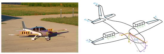
Another interesting flight test campaign on DEP is reported in ref.
[58]; a 1:5 scaled model of the Cirrus SR22T aircraft has been retrofitted with distributed propulsion according to the schema proposed in
26. The primary aim of this experimental activity is to characterise the aircraft flight dynamics by focusing on the influence of the throttle effects on the stability and control derivatives.
26. Scaled model (
left) and possible controls input scheme (
right). Image adapted from
[58].
The study emphasizes the strong inherent interconnections that occur between propulsion and aerodynamics and how these impact on the control features of the aircraft. Lift, pitch and roll are related to the throttle levels; hence this additional input should be used in aircraft control system definition. Additional details on the development and design of the dynamically scaled flying model are collected in ref.
[59].
Other insights on development, manufacturing and testing of non-conventional distributed electric propulsion scaled flying models are available in refs.
[60][61][62].
 +1 credit