Your browser does not fully support modern features. Please upgrade for a smoother experience.
Submitted Successfully!
 +1 credit
Thank you for your contribution! You can also upload a video entry or images related to this topic.
For video creation, please contact our Academic Video Service.
| Version | Summary | Created by | Modification | Content Size | Created at | Operation |
|---|---|---|---|---|---|---|
| 1 | Francesco Fusco | -- | 12015 | 2024-02-09 12:11:37 | | | |
| 2 | Jason Zhu | Meta information modification | 12015 | 2024-02-18 03:06:17 | | |
Video Upload Options
We provide professional Academic Video Service to translate complex research into visually appealing presentations. Would you like to try it?
Cite
If you have any further questions, please contact Encyclopedia Editorial Office.
Fusco, F.; Castrillo, V.U.; Giannetta, H.M.R.; Albano, M.; Cavallini, E. Wireless Communications and Power Transfer on Intra-Vehicular Applications. Encyclopedia. Available online: https://encyclopedia.pub/entry/54967 (accessed on 06 June 2026).
Fusco F, Castrillo VU, Giannetta HMR, Albano M, Cavallini E. Wireless Communications and Power Transfer on Intra-Vehicular Applications. Encyclopedia. Available at: https://encyclopedia.pub/entry/54967. Accessed June 06, 2026.
Fusco, Francesco, Vittorio Ugo Castrillo, Hernan Maximiliano Roque Giannetta, Marta Albano, Enrico Cavallini. "Wireless Communications and Power Transfer on Intra-Vehicular Applications" Encyclopedia, https://encyclopedia.pub/entry/54967 (accessed June 06, 2026).
Fusco, F., Castrillo, V.U., Giannetta, H.M.R., Albano, M., & Cavallini, E. (2024, February 09). Wireless Communications and Power Transfer on Intra-Vehicular Applications. In Encyclopedia. https://encyclopedia.pub/entry/54967
Fusco, Francesco, et al. "Wireless Communications and Power Transfer on Intra-Vehicular Applications." Encyclopedia. Web. 09 February, 2024.
Copy Citation
In the world of space systems and launchers in particular, there is always a strong demand for the reduction of the weight of all components/subsystems that are not related to the payload and simplification of the integration phase. A possible solution to both these problems is the replacement of cables and connectors with wireless systems for communication and power supply.
launcher
aerospace
wireless communication
wireless power transfer
1. Wireless Systems for Communications
1.1. Standards for WPAN and WBAN
WPANs are used to transmit information over relatively short distances between participating nodes. Unlike WLANs, connections made via WPAN involve little or no infrastructure at all. This enables implementing small, energy-efficient and cost-effective solutions for a wide range of devices.
The IEEE 802.15 working group has defined three classes of WPAN differentiated by data rate, battery consumption and QoS. The high-data-rate WPAN (802.15.3) is suitable for multimedia applications requiring very high QoS. Medium-speed WPANs (802.15.1/Bluetooth) are designed to replace the cables of consumer electronic devices and, in their first versions, were oriented for use on mobile phones and Personal Digital Assistants (PDAs) with a QoS suitable for voice applications (9.6 ÷ 64 kpbs). The latest class of IEEE WPAN, Low-Rate (LR) WPAN (802.15.4), is intended to support applications with low (or ultra-low) power and cost requirements, generally a limited need for data rates and QoS and not already addressed by 802.15.1 or 802.15.3 WPANs. LR-WPAN applications typically have a limited need for data rates and QoS.
It is worth observing that there are also other protocols used for LR-WPAN not based on 802.15.4 (a survey of LR-WPAN is shown in [1]), such as ANT, a proprietary protocol (created by ANT Wireless, a division of Dynastream Innovation Inc., then bought by Garmin [1]) operating in the 2.4 GHz Industrial, Scientific and Medical (ISM) band with a data rate which varies from 20 to 60 kbps, and Z-Wave, a proprietary standard developed by Zen-Sys, initially closed and then opened in 2016, operating between 865 and 926 MHz (depending on the regulation of the various countries) with supported data rates equal to 9.6/40/100 kbps (depending on the used modulations).
WBANs are used to operate near or inside the human body to offer real-time monitoring of a patient’s health status and diagnose life-threatening diseases. However, they can also support non-medical applications. The standard to be considered for this type of network is IEEE 802.15.6.
1.1.1. IEEE 802.15.1 and Bluetooth
Bluetooth is a short-range, low-bandwidth WPAN technology. Originally published as IEEE 802.15.1, it has then been managed outside the IEEE by the Bluetooth Special Interest Group (SIG). It operates in the 2.4 GHz ISM band and uses the Frequency Hopping Spread Spectrum (FHSS or the FH-CDMA) transmission scheme. Bluetooth wireless devices and networks are mainly designed for low-power applications using batteries as a power supply. In particular, most Bluetooth devices transmit at a power level of 1 mW (0 dBm) [2].
Bluetooth Low Energy version family (which includes BLE 4.x, Bluetooth 5 @ 2 Mbps and Bluetooth 5 Coded) is certainly the most interesting version and deserves an in-depth examination. Compared to Bluetooth Classic, 40 channels are used, each with a bandwidth of 2 MHz. These channels can be of two types: advertising channels, used for “discovery” functions of devices that can be associated with the network, connection initialization, data broadcasting and data channels used for communication between two connected devices. The adaptive frequency hopping (AFH) mechanism is also supported in order to reduce interference with 802.11-based networks. Four possible roles are expected for a device within a BLE network: peripheral, central, broadcaster and observer [3]. Broadcast and peripheral devices use advertising channels to transmit and receive broadcast data, respectively. A device with the central role is responsible for creating and managing connections with devices with the peripheral role. After a connection between two devices is initiated, they, respectively, acquire the role of master and slave according to the role assigned to them during the connection initialization procedure [3]. The master communicates access to the medium using a TDMA (Time Division Multiple Access)-based polling mechanism, in which it periodically polls its slaves for their corresponding Connection Events (CEs). CEs are uniformly spaced within a configurable periodic interval called a connection interval (CI) [4]. Frequency hopping is used in such a way that each CE uses a different channel. Thanks to these mechanisms, it is possible to obtain very low latencies. Finally, in the classic version of Bluetooth, a network is limited to a “piconet” of eight members, with a master and up to seven slaves (several piconets could still be combined to form a “scatternet”, in order to enable a network topology hierarchical). In the new versions, the number of nodes belonging to a piconet is unlimited.
To ensure even greater ranges, Bluetooth has introduced the Bluetooth Mesh standard. In this case, communication is implemented using BLE advertising and scanning the three channels dedicated to this function. The mechanism used is named the “flooding”, since each network node re-forwards the incoming messages to the destination. Unlike normal BLE advertising, node transmissions in Bluetooth Mesh are not scheduled on the basis of an advertising interval, but they take place after a random pause time. The overall latency is influenced by this mechanism which, however, is necessary to decrease the probability of collision and ensure reliability and scalability of Bluetooth Mesh networks. Consequently, Bluetooth Mesh-type networks are not suitable for applications requiring low latency, such as security systems and closed-loop control and regulation systems [4].
Bluetooth is currently an active technology, commercially widespread, widely supported by COTS-type hardware devices and constantly updated. Thanks to the configurability of some parameters (such as the connection interval and the advertising interval), Bluetooth provides different performances suitable for different operating scenarios. In any case, due to the interdependence of these parameters, an evaluation (experimental or at least by simulation) is still necessary to determine the actual obtainable performances. In this regard, as highlighted in [5], it should be noted that although it is possible to satisfy both low-latency and high-reliability constraints (see the work shown in [3] related to time-critical industrial applications); the simultaneous satisfaction of both requirements for avionics wireless communications applications is not currently achieved.
1.1.2. IEEE 802.15.4
IEEE 802.15.4 (or more briefly 802.15.4) is a constantly evolving standard (a good summary of the standard historical evolution—until 2021—is reported in [6]) characterized by low-power consumption and bandwidth and intended for wireless sensor networks and for monitoring, control and supervisory applications. It does not define a complete protocol stack compliant to the Open Systems Interconnection (OSI) model, but only the PHY physical layer and the Media Access Control (MAC) sublayer of the data link layer of an OSI-compliant stack.
During its evolution, several PHYs have been defined with modulation schemes operating on different frequency bands. The most popular is the one based on the Direct Sequence Spread Spectrum (DSSS) with O-QPSK modulation operating in the 2.4 GHz ISM band, which has been widely implemented and is the reference for most other 802.15.4-based protocols. The maximum data rate supported at the physical layer is equal to 250 kbps while the coverage range is of the order of 10 m (protocols based on 802.15.4 can have wider coverage ranges, as will be seen later).
The mechanism for creating a PAN provided by the MAC sublayer has two classes of devices: Full-Function Devices (FFD) and Reduced-Function Devices (RFD). Each PAN must have an FFD designated as a network coordinator who is responsible for making the PAN apparent to other devices and is responsible for mediating the process of joining the network itself [2].
Both RFDs and FFDs can associate with the PAN coordinator and once joined to the PAN, other FFDs can act as secondary coordinators, making the PAN evident to candidate “child” devices and associating with them as sync “parents”. Furthermore, each FDD node can also communicate with another FDD node, as well as with its own coordinator and with any “child” node (while an RFD can communicate only with its parent FDD). Consequently, the standard enables implementing networks characterized by very different topologies (from star networks to mesh networks), even if no indication is given on how to route messages through multiple intermediaries or to construct the messages themselves (these operations are delegated to the higher levels of the OSI stack not defined by 802.15.4.) [2].
Once a device is associated with a PAN, two operating modes are possible (according to the original version of the standard): “beacon enabled” and “non-beacon enabled” [6]. It is useful to briefly illustrate their operation (as reported in [2][6]) because it is the basis of the other protocols that 802.15.4 and other standards covered in this document use.
In the “beacon-enabled” mode, the network coordinator divides the time into a series of constant intervals, called superframes, composed by a certain number of fixed intervals called slots, used to manage access to the shared medium. A superframe consists of two main sections. The first section is the active one and is used to exchange frames between the various nodes of the network. It is divided into two parts: contention access period (CAP) and contention-free period (CFP). In the first part, the nodes use the Carrier Sense Multiple Access with Collision Avoidance (CSMA/CA) algorithm in the “slotted” version to access the channel. In the second part, the TDMA access technique is used and the transmission channel is reserved only for nodes with specific needs in terms of throughput or delay; guaranteed time slots (GTS) are assigned to these nodes (by means of a negotiation in the CAP) in which it is possible to transmit without interference from other network nodes. The second section represents an idle time interval in which no transmissions are enabled; accordingly, all nodes can switch off their radio module and go into the sleep mode in order to save energy. Each super frame begins with the transmission of a frame beacon used by the coordinator to synchronize the nodes associated with the superframe, to describe the structure of the superframe (duration of the active and inactive sections, definition of the components participating in the active period, etc.), and to identify the network PAN.
In the “non-beacon-enabled” mode, access to the shared medium is managed exclusively through the CSMA/CA algorithm in the “unslotted” version. A periodic transmission of the beacon is not foreseen (the beacon is transmitted only following an association request initiated by an end device) and there is no synchronization service for the FFD and RFD nodes. When an RFD comes out of the sleep mode (output managed by a higher protocol layer than the MAC) it must interrogate the network coordinator to be able to transmit the pending messages. This mode enables great energy saving by the RFD nodes, which can operate in the sleep mode for longer periods, but imposes that the coordinators are always active to avoid any unanswered requests. Furthermore, the timely delivery of the messages cannot be guaranteed as the MAC sublayer of the standard does not define the “wakeup” schedule of the RFD nodes. The service provides a “best effort” quality [6].
As regards the evolution of the 802.15.4 standard, the 802.15.4e amendment has particular importance because it makes some changes to the MAC sublayer by introducing three new operating modes designed for industrial applications: time-slotted channel hopping (TSCH), deterministic and synchronous multichannel extension (DSME) and low-latency and deterministic networks (LLDN). A short description of these modes (excerpted from [4][6][7]) is shown below.
TSCH is an operating mode (inherited from the WirelessHART standard) designed for control and automation applications requiring a real-time response from the network. It is based on two main concepts: time slotting (i.e., subdivision of time into time intervals called timeslots) and channel hopping. TSCH runs on a “non-beacon-enabled” mode and uses the concept of slotframe (instead of the 802.15.4 superframe), which is a collection of timeslots that repeats periodically over time. The duration of a timeslot (which typically ranges from 6 to 10 ms) and the number of timeslots in a slotframe are configurable. The length of the slotframe is based on a trade-off between power consumption and throughput [4] (a decrease in the slot frame increases both power consumption and throughput, and vice versa). As mentioned before, in addition to time slotting, TSCH also uses channel hopping to decrease the impact of interference and fading on a channel. The nodes, in fact, have more channels available to be able to communicate (16 @ 2.4 GHz). The combination of timeslots and frequency channels creates cells that can be used for transmission by the nodes and enables a scheduling matrix of these cells to be setup both in time and in frequency. The standard defines two types of cells: dedicated cells, used exclusively by a specific transmitter to send its frames without contention, and shared cells, i.e., cells used between multiple transmitters with contention management (using, for example, CSMA/CA). Thanks to channel hopping, a first unsuccessful transmission in a given cell can be repeated in another cell in order to avoid noisy channels (due to interference, fading, etc.). If all channels were used at the same time with channel hopping, the aggregate throughput and scalability of the network could increase. However, all the slave nodes in the network usually communicate with the same master node (therefore with a centralized architecture), which is not able to receive and transmit on multiple channels simultaneously; therefore, the nodes will be forced not to transmit simultaneously regardless of the used channel-hopping scheme.
DSME is another MAC-level mode designed for applications (industrial and commercial) requiring rigorous timeliness and reliability. In particular, a superframe with a structure similar to the original version of the standard (i.e., superframe with CAP and CFP) is used, with an Enhanced Beacon (EB) inherited from the original 802.15.4 one. The mode also supports the use of multiple channels in the same superframe. The nodes transmit in the CAP using the channel number selected during association with the network, while they transmit in the CFP using the channel assigned for their guaranteed time slots (DSME-GTS). The channel assignment can also use channel diversity methods (channel adaptation or channel-hopping). DSME can also reduce the CAP in order to save energy by replacing it with CFP. Finally, DSME enables defining multi-superframes consisting of cycles of repeated superframes.
LLDN is the mode that can be used for industrial and commercial applications requiring low and well-defined latency. LLDN only supports star topology networks managed by an appropriate coordinator. In addition, it uses a specific version of the superframe based on the introduction of new timeslots: a beacon timeslot (for synchronization), timeslots for downlink and uplink (optional, use for managing data transmission in both directions), a timeslot for data transmission, a Group ACKnowledgment packet timeslot (GACK), a data retransmission slot (for failed frames indicated in the GACK), bidirectional timeslots for transmitting data to and from the PAN coordinator.
Note that the IEEE 802.15.4e amendment does not define how to implement some of the mechanisms introduced. For example, the scheduling algorithms in the case of the TSCH mode are not defined. Their implementation is, therefore, left to the developer.
Finally, it is worth mentioning the amendments 802.15.4g and the 802.15.4z. The first one defines alternative PHYs (including one based on OFDM [8]) and operates in the sub-GHz band with a coverage range of up to 1 km [4] (it can be used as a benchmark against other standards operating in the sub-GHz band, in particular 802.11ah). The second one updates the UWB PHY [9], initially included in the 2011 version of the IEEE 802.15.4 with sub-GHz, 3.1 ÷ 4.8 GHz and 6.0 ÷ 10.6 GHz operating bands.
The main wireless sensor network standards for industrial applications based on 802.15.4 are described below, namely ZigBee, WirelessHART, ISA100.11a and WIA-PA. The information reported is excerpted from [2][4][10][11][12].
ZigBee
Introduced in 2004, ZigBee is the first standard implemented starting from the layers (PHY and MAC) provided by IEEE 802.15.4, with the addition of the network layer and the framework for the application layer. The architectural scheme of the protocol stack is shown in [10]. Star, tree and mesh network topologies are supported using nodes with different characteristics, namely ZigBee Coordinators (ZC), ZigBee End Devices (ZEDs) and ZigBee Routers (ZR) (see [10] for further details about network these nodes and the network topologies).
As far as the physical layer is concerned, ZigBee inherits from 802.15.4 the O-QPSK PHY operating in the 2.4 GHz band, the BPSK PHY operating in the 868 MHz (used in Europe) and 915 MHz (used in USA) bands and the FSK PHY located in the 863–876 MHz and 915–921 MHz bands [10]. The data rate can be equal to 20, 40, 100 and 250 kbps depending on the PHY and frequency band used. As regards the MAC sublayer, ZigBee supports both “beacon-enabled” and “non-beacon-enabled” versions of 802.15.4. Obviously a “non-beacon-enabled” configuration simplifies the implementation, but involves the limitations previously observed for 802.15.4. However, the ZigBee stack configurations implemented in the devices may not support the “beacon-enabled” mode.
With reference to the channel access method, ZigBee defines two versions of CSMA/CA, slotted and unslotted, used, respectively, for the beacon-enabled and non-beacon-enabled modes. In both cases, there is a back-off mechanism (i.e., waiting for a randomly calculated pause after a collision) which can cause transmission delays and non-deterministic behavior, especially in the presence of high traffic.
Interferences within the operating frequency band are managed using an approach based on a technique known as frequency agility: when a device realizes that its operating channel is subject to interference, it looks for the best channel to transmit on and, under the direction of the coordinator, shifts traffic to the newly determined configuration. Since the error statistics and the possible channel change notification always travel on the channel subject to interference, the overall network modification could take some time, resulting in a much slower solution than the frequency hopping (where a predefined hopping pattern is used).
As far as routing is concerned, two methods are provided: “tree routing”, for tree-type topologies, and “Ad hoc On-demand Distance Vector (AODV) routing” for mesh-type topologies (for further details, see [11]).
Finally, it is worth observing that for applications requiring a deterministic delay (latency) and controllable responses the star topology is the best option, even though robustness and scalability may be affected; in fact, if the connection path between two nodes is interrupted, there are no more possibilities to recover communication using alternative paths.
WirelessHART (IEC 62591)
WirelessHART is a communication standard designed for industrial automation processes. It operates in the 2.4 GHz band, uses 15 different channels supported by a PHY layer inherited from 802.15.4 and shares many characteristics with the 802.15.4e amendment.
WirelessHART combines TDMA and CSMA access methods. In particular, the advantages of TDMA and channel hopping (in slotted hopping mode) are exploited to counteract the effects of fading and interference. The operating strategies of the MAC layer are based on the Time Synchronized Mesh Protocol (TSMP) designed by Dust Networks. As in the case of TSCH, a two-dimensional array made up of timeslots and channels is used for the media access. Time slots are grouped into superframes that are continuously repeated throughout the lifecycle of the network. Variable length superframes are also supported and at least one superframe must be enabled. Other superframes can be added or removed during network operations and are managed by the network manager. The duration of the timeslot is fixed at 10 ms. The scheme used enables multiple devices to transmit at the same time using different channels. However, a single device can only use one channel per timeslot. Finally, there is a mechanism that identifies noisy channels and places them in a sort of blacklist.
The main elements of a WirelessHART network are gateway, access point (AP), network manager and field devices. Field devices, which include network sensors, have full routing capabilities. The AP, on the other hand, is only used to connect the field devices to the gateway. Finally, the network manager performs some operations necessary for the functioning of the network in a centralized manner (network configuration, scheduling and management of communications between field devices).
The basic topology supported by WirelessHART is mesh. Low latencies can only be obtained using star-type configurations and with very short superframes which, however, penalize the scalability of the network. Consequently, WirelessHART networks are constrained either by latency or by the number of nodes to connect.
Another feature of this standard is the possibility of using graph routing (for further details, see [11]), in addition to the source routing mainly used in the network commissioning phase for diagnostic and testing activities.
Finally, WirelessHART is a standard designed to support integration with industrial automation devices that comply with the HART protocol (Highway Addressable Remote Transducer), so it may have limited use depending on the application context.
ISA100.11a-2011 (IEC 62734)
ISA100.11a is a full-stack standard designed for industrial wireless sensor networks that require secure and reliable communications for non-critical closed-loop or open-loop monitoring, alerting, supervision and control applications. For the physical level, it adopts the O-QPSK DSSS modulation at 2.4 GHz as defined by the IEEE 802.15.4-2006 standard, while it replaces the MAC of that same standard with an alternative one supporting frequency hopping. The single hop coverage range is up to 100 m.
ISA100.11a is similar to WirelessHART, but unlike the latter it offers flexibility in customizing network operations. At the MAC level, it uses TDMA and CSMA/CA and channel hopping. CSMA/CA is typically used for message retries, association requests, exception reporting and burst traffic. The use of each channel is reduced by means of timeslot synchronization and channel hopping resulting in an optimization of the spectral occupation. Communications take place in timeslots with a constant and configurable duration (from 10 to 12 ms), grouped in a superframe that repeats periodically over time. The superframe length is configurable and may differ for each node. In general, longer superframes result in higher latencies but enable saving energy and a more efficient bandwidth allocation.
The way frequency hopping is used is based on slotted hopping and is similar to that of WirelessHART except that in ISA100.11a each device identifies the actual channel to use by using a preset pattern which provides a specific sequence of channels to follow when changing frequency. In order to limit collisions with 802.11 networks, the standard recommends five hopping patterns. In addition to slotted hopping, ISA100.11a also supports two further techniques: slow hopping, based on grouping several contiguous timeslots on a single radio channel (with configurable hopping periods) and hybrid hopping, which simply combines slotted and slow hopping.
The devices of an ISA100.11a network belong to two classes: Field devices and Infrastructure devices. Field devices include devices equipped with routing capabilities (the latter can be disabled to optimize network performance in terms of latency or power consumption) and I/O devices that do not support routing but only provide data and/or use data provided by other nodes. Infrastructure devices include backbone routers, gateways and system and security managers. Backbone routers act as proxies as they route data packets to their destinations through a backbone network to which the gateway is also connected. The supported topology can be either mesh or star.
A strong similarity with WirelessHART also remains in terms of routing, since the algorithms used are the same. However, there are several differences such as faster addition of a node for a dense network, higher reliability and latency in cyclic communication and less adaptability to changes.
Finally, even if the standard does not limit the number of nodes in the network, as in the case of WirelessHART, a trade-off must be made between latency and the number of nodes that can be connected, also considering the possible presence of bidirectional traffic. In fact, an increase in the number of hops or the presence of bidirectional traffic doubles the latency or halves the number of connectable nodes.
WIA-PA (IEC 62601)
Wireless Networks for Industrial Automation-Process Automation (WIA-PA) is a full-stack standard fully compatible with 802.15.4 used for industrial automation processes. The MAC sublayer is enhanced by a combination of CSMA, TDMA and frequency hopping schemes built on top of 802.15.4. To ensure the reliability of communications between network devices as well as the relative synchronization, WIA-PA uses superframes with a structure compatible with 802.15.4 and a “beacon-enabled” operating mode. It should be noted that the WIA-PA MAC substantially has anticipated the same technology then defined by the 802.15.4e amendment for the DSME operating mode. There are three frequency hopping mechanisms used: adaptive frequency switching (AFS), used during superframe communications to change channels in the presence of interference; adaptive frequency hopping (AFH), used in intra-cluster communications (a sort of sub-network in which a WIA-PA network is organized) to change the channel randomly based on the quality of the channel itself; timeslot hopping, always used in inter-cluster communications to regularly switch channels for each timeslot according to a hopping sequence defined by the network manager.
As far as the topology is concerned, WIA-PA combines a hierarchical cluster-based architecture with a mesh-type architecture between the star nodes of the cluster hierarchy (cluster heads). The main elements of the architecture are routing devices, gateway devices and field devices. The routing devices have the role of cluster heads and have the task of building and monitoring their own cluster and routing the data packets received towards the backbone network. For each network, a redundant cluster head is recommended to act as a backup in order to prevent a failure on the cluster head from compromising the entire network. The field devices, which are members of each cluster, carry out the measurements and send them to the cluster head without routing capabilities. Finally, the gateway devices receive data from the routers and enable different communication methods and for transforming the WIA-PA protocol into a different protocol. Data packets are routed using static routing.
1.1.3. WPAN Standard IEEE 802.15.3
The 802.15.3 standard, approved in its first version in 2003, defines the MAC sublevel and the PHY level for high-data-rate WPAN networks [13]. The MAC enables quick and easy network formation, provides excellent QoS, security through AES encryption with 128 bit key in the CCM (Counter with Cipher block chaining—Message authentication code) mode [14], and methods for coexisting with other wireless networks in the same band. The PHY operates in the unlicensed 2.4 GHz band with supported data rates of 11 up to 55 Mbps at distances greater than 70 m. In the subsequent versions, the efficiency of the MAC sublayer has been improved, a 60 GHz operating frequency band has been added, new data rates with a maximum value greater than 5 Gbps have been supported, and beamforming negotiation for the transmitter (in order to increase the communication range and transmission overhead reduction) has been introduced [15]. Finally, further upgrades have been added by three new amendments, that have been available since 2017 (the interested reader can find more details in [16][17][18]). The 802.15.3 network topology involves the use of a piconet, i.e., an ad hoc wireless communication network covering a circular area with a radius of 10 m and made up of several connected devices (nodes) called DEVs (devices). One of the network nodes must necessarily assume the role of PicoNet Coordinators (PNC) in order to: manage its operation, coordinate the media access, send information to DEVs and respond to requests for association and use of the channel [19]. The operating mode of the piconet is similar to the “beacon-enabled” mode of 802.15.4 thus providing the use of superframes, a contention access period and a channel time allocation period (for further details, see to [19]). Finally, non-coordinator DEVs can also create dependent piconets relying on the PNC of the starting network (parent piconet) to allocate the time slots dedicated to their operation [19].
1.1.4. IEEE 802.15.6
This is a standard specifically dedicated to Wireless Body Area Networks (WBAN), i.e., networks designed to offer real-time monitoring of a person’s health and diagnose life-threatening diseases. Further, 802.15.6 also supports application domains not necessarily related to medicine, such as data file transfer, video streaming, gaming and social networking applications [20]. The expected coverage range is about 3–5 m [21]. The description below is excerpted from [21][22].
802.15.6 only defines the PHY layer and MAC sublayer of a WBAN. As far as the physical layer is concerned, three distinct PHYs are defined: narrow band (NB), ultra-wide band (UWB) and Human Body Communications (HBC). NB PHY supports various frequency bands (including the 2.4 GHz ISM), DBPSK, DQPSK, D8PSK and GMSK (but only in the 420 ÷ 450 MHz band) modulations and a net information data rates range from 57.5 kbps to 485.7 kbps. UWB PHY operates in two frequency bands (low band and high band), each of which is divided into channels characterized by a bandwidth of 499.2 MHz, with typical data rates range from 0.5 Mbps to 10 Mbps. Finally, HBC PHY works in two frequency bands centered, respectively, at 16 MHz and 27 MHz with a bandwidth of 4 MHz. The frame used at the physical layer, called Physical Protocol Data Unit (PPDU), is illustrated in [20] for each PHY.
Above the PHY layer, the standard defines a sophisticated MAC that controls access to the channel. The time axis is divided into beacon or superframe periods of equal length. Each superframe contains a number of slots (of equal duration) allocated to enable data transmission. Beacons are used to delimit the superframe and allocate slots. If the beacon is not used (“non-beacon” mode), the boundaries of the superframe are defined by polling frames. The network coordinator (hub) transmits the beacons in every superframe, except in idle superframes or unless it is prohibited by regulations (as in the case of the Medical Implant Communications Service—MICS—band). There are three different modes of communication. In the first one, the superframe, delimited by the beacon, is divided into phases: Exclusive Access Phases (EAP1 and EAP2), Random Access Phases (RAP1 and RAP2), Managed Access Phase (MAP) and Contention Access Phase (CAP). EAP is used to carry high-priority or emergency traffic. RAP and CAP are used for non-recurring traffic. MAP, in turn, includes Type I and Type II phases, and is used for uplink and downlink bidirectional and unidirectional traffic allocations. The second one is a “non-beacon” mode and the entire duration of the superframe is covered only by MAP. The third mode is a “non-beacon” mode like the second, but it only supports Type II unscheduled polled or posted allocations (or a combination of both).
The access mechanisms used in each period of the superframe are divided into three categories: random access, which uses CSMA/CA or Slotted ALOHA for resource allocation, improvised and unscheduled access, based on unscheduled polling/posting, and scheduled access, which defines the slot allocation in one or multiple successive superframes. The first mechanism is used in EAP, RAP and CAP, while the others are used in MAP and non-beacon modes.
1.2. Standards for WLAN
WLAN Standard IEEE 802.11
The IEEE 802.11 (or briefly 802.11) standard was created in 1997, although it only became popular in 1999, when the 802.11a and 802.11b versions were introduced. Below, a brief description extracted from [2][4] is reported.
In an architecture based on 802.11, the basic organizational unit is given by the Basic Service Set (BSS) which, from a conceptual point of view, can be seen as a set of independent wireless stations logically organized to communicate with each other. BSS can be of three types: Independent BSS (IBSS), Infrastructure BSS and Mesh BSS (MBSS). IBSS is the simplest one: all the stations communicate with each other without the aid of a centralized node or message forwarding or relaying services. In any case, each station can communicate with other stations (based on the existing topology) but cannot act as a relay for the transfer of data packets. As a result, it is not guaranteed that all the stations within an IBBS can communicate with each other. This problem is solved in MBSS, where each station establishes communications with neighboring stations for mutual message exchange while ensuring multi-hop relaying. Finally, Infrastructure BSS is the most common, and is based on a centralized architecture in which each station communicates with an access point (AP), which is responsible for forwarding direct messages to the other stations. The AP also acts as a bridge to a possible Distribution Service (DS), such as an ethernet backbone. Furthermore, a Station-To-Station Link (STSL) mode is also supported. It was established using a procedure called Direct-Link Setup (DLS) and it is available only in the case of Infrastructure BSS.
As far as OSI stack is concerned, 802.11 defines only two layers: the MAC sublayer of the data link layer (DLL) and the physical layer (PHY). The PHY layer defines a number of transmission schemes including modulation and coding techniques for wireless communications. In the MAC sublayer, the two basic access schemes are Distributed Coordination Function (DCF) and Point Coordination Function (PCF). DCF is the default scheme for 802.11-based systems and is based on CSMA/CA. On the other hand, when a PCF scheme is used, the wireless communication is organized with time slots called superframes. Each superframe period is further divided into a contention period (CP), where DCF is used, and a contention-free period (CFP), where PCF is used. An AP then periodically polls the high-priority nodes and assigns broadcast slots for time-critical applications. The PCF works only if the network infrastructure operates in a centralized mode. However, PCF is poorly supported by manufacturers. To meet the different quality of service requirements that applications may require, in addition to the previous ones, the Hybrid Coordination Function (HCF) scheme may also be available (i.e., a combination of DCF and PCF with several variations). Finally, for mesh-type network configurations an additional coordination function called Mesh Coordination Function (MCF) is available.
802.11 operates in several frequency bands. 2.4 GHz ISM band and 5 GHz Unlicensed National Information Infrastructure (UNII) band are the most commonly used. Support for one or more bands depends on the version of the standard considered. Each band is then divided into channels, and each channel can be associated with a given network using 802.11. An example of this subdivision, related to the 2.4 GHz band, is shown in [2].
The evolution of the IEEE 802.11 standard over time has been characterized by sequences of successive versions. In some cases, some versions have been grouped into a single standard. A brief overview, excerpted from [4][23], starting with the relatively new ones (802.11n/ac, 802.11ah and 802.11ad) and ending with the latest generation ones (802.11ax, 802.11be and 802.11ay), is reported below. More details for the older versions (802.11a/b/g) are available in [5].
802.11n/ac—The 802.11n version (2009), operating both in the 2.4 GHz and 5 GHz bands, supports a data rate up to 600 Mbps thanks to MIMO (Multiple Input Multiple Output) techniques (multiple antennas are used to transmit and receive data), channel bonding (in the PHY layer adjacent channels are combined in order to increase throughput) and frame aggregation (multiple frames are aggregated in order to reduce interframe intervals and headers). The 802.11ac version (2013), operating in the 5 GHz band, increases the throughput offering a data rate up to 2.34 Gbps, with a maximum theoretical potential of 6.77 Gbps in multi-antenna configurations. Compared to 802.11n, the 802.11ac version supports higher cardinality modulations, wider bandwidth channels, more MIMO spatial streams, and the down-link Multi-User MIMO (MU-MIMO) in the 5 GHz band (up to four simultaneous downlinks connected to the same AP are supported).
802.11ax—Standardized in 2020, this version is designed to operate in all bands between 2 and 7 GHz (as bands will become available for use by the 802.11 standard), in addition to the classic 2.4 and 5 bands GHz. 802.11ax also aims to improve the performance of WLAN deployments in scenarios characterized by a large number of APs and their associated nodes deployed in limited spatial regions (for example, a stadium or an airport). The theoretical maximum throughput is quadrupled compared to 802.11ac (9.6 Gbps). Commercially known as Wi-Fi 6, 802.11ax is the current standard for the current generation of Wi-Fi (note that devices marketed as Wi-Fi 6 work in the 2.4 and 5 GHz bands, while the Wi-Fi 6E nomenclature does reference to products that support the 6–7 GHz band).
802.11be Extremely High Throughput (EHT)—This version is expected to become an effective standard in 2024. The goal is to support extremely high data rates compared to 802.11ax, with very wide bandwidths and high operating frequencies. Also compared to 802.11ax, reliability should also improve thanks to the simultaneous coverage of multiple base stations. 802.11be is expected to be the potential successor to Wi-Fi 6 and will likely be certified by the Wi-Fi Alliance as Wi-Fi 7. Features expected for 802.11be include bandwidth per channel up to 320 MHz, 16 spatial streams, coordination of activities of multiple APs both at the MAC (Coordinated OFDMA, Coordinated Spatial Reuse, Coordinated TDMA) and PHY (Coordinated Beamforming, Coordinated Joint Processing) level [24], integration of the Time-Sensitive Networking (TSN) extensions defined by IEEE 802.11 to support low-latency real-time data traffic [23].
802.11ah—This version was standardized in 2016. It operates in the sub-GHz 900 MHz band, uses contention-based PHY/MAC layers, and leverages on versions prior to 802.11n, with the goal of minimizing power usage (becoming a low-power version) and improving the management of mesh-type networks. The maximum theoretical data rate is equal to 347 Mbps in extreme configurations and the communication range is several times that of the 802.11n and 802.11ac versions. 802.11ah can serve up to 8192 stations per AP with a coverage range of up to 1 km, which can be further increased with the availability of relay-type functionality. To limit interference between stations and possible collisions, it introduces the concept of Restricted Access Windows (RAW), i.e., a mechanism that restricts access to the channel to a specific group of stations in correspondence with specific time slots. The stations assigned to specific slots within a RAW compete for the medium through the Enhanced Distributed Channel Access (EDCA), i.e., a variant of the DCF parameterized on the basis of different access categories defined for the stations (it is one of the mechanisms defined by HCF). The characteristics of the RAW and the relative assignment of the stations is configurable and can change at each beacon interval. Consequently, properly configured, RAW can introduce a certain degree of determinism into the network. 802.11ah also supports other mechanisms, such as the Traffic Indication Map (TIM) and the Target Wakeup Time (TWT), through which it is possible to customize (also together with the RAW) the network in order to reduce the latency and/or obtain an energy saving by the devices implementing the network.
802.11ad/ay—Standardized in 2012, 802.11/ad is designed to work at 60 GHz. In the original version it was supposed to support a maximum data rate of 6.8 Gbps, but in the current version and in the related implementations it supports up to 4.6 Gbps (so slower than 802.11ac-compliant products). In any case, the form factor of the products is very small due to smaller used wavelengths. 802.11ay is an improvement on 802.11ad (approved in 2021), operating with the same contention-based approach and at the same frequencies, with support for channel bonding and an improved spatial spectrum reuse. The communication has a short–medium range (up to 500 m) in free space conditions with a maximum supported data rate of 176 Gbps.
As highlighted in [23], 802.11n, 802.11ac, 802.11ad, 802.11ax and 802.11ah standards are all now quite mature, however the availability of hardware for the 802.11ax and 802.11ah versions is quite recent (starting from the end of 2019 in case of 802.11ax and from mid-2020 in the case of 802.11ah). For the 802.11ay and 802.11be ETH versions (for the latter, it is worth remembering that the definitive standard is not yet released), the availability of hardware is currently very limited or absent.
Analyzing the previous figures, it is possible to conclude that for applications requiring low-power consumption and data rates lower than 1 Mbps, the most attractive version is 802.11ah. As previously mentioned, 802.11ah also offers the possibility of configuring various characteristics of the PHY and MAC levels in order to optimize some characteristics such as latency and energy consumption. For high data rates, assuming to work in the 2.4 GHz and/or 5 GHz bands, 802.11n/ac/ax versions can be used. Although the 802.11n version is slightly less energy-intensive, the related products may soon become obsolete, so the preferred choice should be 802.11ax. This version can also be used for mission-critical applications [23]. 802.11ac can be a suitable solution in the 5 GHz band, also considering its extensive commercial support regarding hardware devices [23]. If it is necessary to operate in the 60 GHz band, 802.11 can be adopted as 802.11ay is still poorly supported.
Finally, as far as energy saving is concerned, it should be noted that 802.11 provides a basic “power saving” operating mode in which a station enters a “doze state” with all the RF components switched off. This mode is managed through a mechanism based on the TIM and the DTIM (Delivery TIM) [25]. 802.11ah improves on this mechanism by adding segmentation and defines an additional mode of operation for stations where there is no need to periodically “wake up” for beacon reception. For these stations, the AP uses the Target Wake Time (TWT) information (exchanged with the frame association request and association response), which is used to define when and how often the stations must wake up for uplink or downlink transmissions [25]. The mechanism is also supported by 802.11ax [26] and 802.11be in the Restricted TWT version (which forces all 802.11be-compatible devices to terminate their transmission before a TWT period begins [27]).
1.3. Standards Comparison
WirelessHART, ISA100.11a and WIA-PA are standards for industrial applications adopting the PHY defined by the IEEE 802.15.4 and operating in the 2.4 GHz band. They are based on full-stack protocols centrally managed by a network (or system) manager. WirelessHART and ISA100.11a define their own MAC while WIA-PA is fully compatible with 802.15.4 (in particular it is similar to the DSME defined by 802.15.4e). They all use frequency hopping mechanisms in order to improve the reliability of transmissions. In particular, ISA10.11a offers better performance when an interference generated by IEEE 802.11-type networks is present (thanks to the use of predefined hopping patterns operating in channels that do not overlap with those typically used for 802.11), while WirelessHART provides a greater degree of randomness in channel hopping. WIA-PA, compared to the other ones, adds adaptive characteristics to frequency hopping. WirelessHART, ISA100.11a, and WIA-PA can all offer good latency performance by using the TDMA access method (in addition to CSMA). The mechanism used by WIA-PA is a hybrid between TDMA and CSMA so its performance in terms of latency can be considered slightly lower. All three standards, being based on 802.15.4 PHY, enable low-power consumption; furthermore, in the case of ISA100.11a and WIA-PA, it is possible to disable the routing capabilities of some network devices in order to minimize the energy consumption. All three standards provide scalability characteristics, but as the number of nodes increases, it is necessary to use mesh-type topologies with worse performance in terms of latency. Furthermore, since their protocols are based on TDMA, the density of the network is limited by the need for synchronization and by the possible timeslot–device association. Finally, while ISA100.11a and WIA-PA support different communication protocols, WirelessHART is compatible only with the HART protocol.
ZigBee is also a standard used in industrial applications. Like WirelessHART, ISA100.11a and WIA-PA it is based on the PHY of 802.15.4 at 2.4 GHZ, but it also supports the sub-GHz one. Compared to previous standards, it is characterized by greater simplicity. It has good scalability characteristics but substantially using only CSMA-type access techniques, it is not suitable for applications requiring a network with determinism and low-latency characteristics. As far as interference reduction is concerned, a simpler but less robust mechanism (frequency agility) as compared to WirelessHART, ISA100.11a and WIA-PA, which in turn can lead to increased network latency. The protocol enables low energy consumption with the possibility for some nodes to operate in the sleep mode. This mode is managed by the application layer of the nodes with a consequent worsening, once again, of the network latency. In conclusion, this protocol should be preferred due to its simplicity if the latency of the network is not a binding parameter.
As regards the IEEE 802.15.4e amendment, it defines three operating modes, TSCH, DSME and LLDN, which can rely on different PHYs (always defined in 802.15.4), to be used for process control and automation applications where a real-time response from the network (TSCH) is required, for applications needing determinism and reliability (DSME) and for applications requiring a network characterized by a very low and confined (below a certain threshold) latency (LLDN). Further, the amendment does not define how some mechanisms underlying the aforementioned operating methods must be implemented. This implementation is up to the developer. For example, in the case of TSCH, it is not defined how to implement the scheduling for the medium access even though it impacts on the performance of the network itself. A custom implementation of mechanisms not defined by the standard could enable customization of the quality of service provided by the network (in any case, scalability and latency are always limited by the number of nodes that must be connected to the network). However, the mechanisms supported by TSCH are similar to those used in WirelessHART and ISA100.11a, so the obtainable performances should be similar. Going back to the physical level, the above operating modes can be applied to different PHYs, for example operating at 2.4 GHz (as in the case of WirelessHART, ISA100.11a and WIA-PA) or in the sub-GHz band (as defined in IEEE 802.15.4g). In [28], an example where a modified version of the LLDN mode is used in conjunction with the IR-UWB (Impulse-Radio Ultra-WideBand) PHY (defined in 802.15.4-2011) is shown.
BLE also defines the entire protocol stack and moreover, it has some configurable parameters that can highly influence the network performance. The power consumption is low and characterized by higher efficiency (energy per transmitted bit) than ZigBee. Latency is also very low but only in star-type configurations (provided that the limitations due to the coverage range enable the use of this topology). It worsens, together with the reliability, in the case of mesh-type networks. Finally, there are mechanisms that increase the reliability of the connections, at the same time penalizing the supported data rate.
If WPAN with high data rates are needed, 802.15.3 can be an option. This standard has several similarities with 802.15.4 as regards the MAC, but at the same time it defines a PHY operating at 2.4 GHz characterized by a data rate in the order of tens of Mbps. Even higher data rates are supported by 802.15.3 also in other bands (e.g., 60 GHz).
High data rates are also supported by different versions of 802.11. 802.11ah (a version (designed for the IoT and for industrial applications), operating in the sub-GHz band, consists of a MAC characterized by many configurable parameters that make it possible to significantly change performances and power consumption of the devices connected to the network. 802.11ah essentially enables making a trade-off between supported data rate, coverage range and latency (good latency performance can be achieved for limited-scale networks). 802.11ax, corresponding to the Wi-Fi 6, works in the 2.4 and 5 GHz bands (further, it is designed to operate in the entire 2–7 GHz range), supports high data rates and can also be used for mission-critical applications. 802.11n should be considered obsolete for new applications (unless 802.11ax-compliant devices are no available for the considered application context). 802.11ac can be a suitable solution in the 5 GHz band, also considering given the wide commercial support for the related hardware. Finally, 802.11be, not yet approved to date, is promising for future applications as it is able to support the set of Time-Sensitive Networking (TSN) standards for low-latency and very high-reliability communications.
If the application range is in the order of a few meters, 802.15.6 could be used. It is a standard characterized by very low transmitted power and medium–low data rates (depending on the PHY used), but it is mainly designed for electromedical rather than space applications (indeed, it is not included in the list of communication standards applicable for intra-vehicular communications in space missions [2]).
2. Wireless Technologies to Transfer Electric Power
The terms wireless power transfer (WPT), wireless power transmission, wireless energy transmission (WET) and electromagnetic power transfer indicate the transmission of electromagnetic energy without the physical connection of electrical cables. Regardless of the method to transfer energy, all wireless power transmission systems have in common a transmitter, driven by electrical energy from a power supply, that generates a time-varying electromagnetic field which transmits energy through space to a receiver which, in turn, extracts energy from the field and provides it to a load. The input power to the transmitter is converted into an oscillating electromagnetic field by some type of “antenna”. This device could be a wire coil that generates a magnetic field, a metal plate that generates an electric field, an antenna that radiates radio waves or a laser that generates light. A similar “coupling device” on the receiver converts the oscillating fields into electric power [29].
Wireless power techniques mainly fall into two categories, “near field” and “far field”. In near-field or non-radiative techniques, power is transferred over short distances by magnetic fields, by inductive coupling between wire coils, or by electric fields, by capacitive coupling between metal electrodes. In far-field or radiative techniques, power is transferred by beams of electromagnetic radiation, such as microwaves, infrared or laser beams [29].
The near-field or non-radiative region, is the area within approximately one wavelength (λ) of the antenna where the oscillating electric and magnetic fields are separated and power can be transferred via electric fields by capacitive coupling (electrostatic induction) between metal electrodes or via magnetic fields by inductive coupling (electromagnetic induction) between wire coils. These fields are non-radiative, which means that the energy remains a short distance away from the transmitter. If there is no receiving device or absorbing material within their limited range to “mate” to, no energy exits the transmitter. The fields, and therefore the transmitted power, decrease very rapidly with distance, so if the distance between the two “antennas” is much greater than the diameter of the “antennas”, very little power will be received. These techniques therefore cannot be used for long-range power transmission [29].
Resonance, as in resonant inductive coupling, can greatly increase the transfer efficiency between antennas, enabling efficient transmission at slightly greater distances, although the fields still decrease rapidly [29].
Far field or radiative region means a region that extends beyond a wavelength (λ) of the antenna, the electric and magnetic fields are interdependent and propagate as an electromagnetic wave; examples are radio waves, microwaves and light waves. This part of the energy is radiative, meaning that it leaves the antenna whether or not there is a receiver to absorb it. The part of energy that does not hit the receiving antenna is dispersed and dissipated in the system [29].
As just said, two important parameters of any power transmission system are the operating frequency which determines the wavelength and the efficiency (fraction of transmitted energy that is received). Regarding the latter, it is difficult to provide reference numbers, but only qualitative elements can be provided, as this parameter strongly depends on the configuration, such as frequency used, size and shape of the “antennas”, distance between the antennas and reciprocal orientation as well as circuits of compensation. Some examples of the inductive transmission method in resonance are shown in [30].
Wireless power transfer can be used to power transmitter or receiver nodes in a wireless communication network. This type of application is known as “Wireless Powered Communication (WPC)”. In Wireless Powered Communication Networks (WPCN), wireless devices communicate using only the energy collected by wireless chargers. Typically, in WPCNs, two types of wireless chargers are considered. The first type aims at providing wireless charging, called an Energy Access Point (E-AP). The second type can also support data communication and function as a Data Access Point (D-AP) and is referred to as a Hybrid Access Point (H-AP). Research on WPCNs is twofold. The first one focuses solely on wireless charging, i.e., wireless power transfer and information transmission are separate. The second direction is on Simultaneous Wireless Information and Power Transfer (SWIPT), where wireless charging and information transmission are coupled to achieve a compromise [31].
2.1. ”Near-Field” Power Transmission Mechanisms
In inductive and capacitive wireless power systems, transmitters (TX) and receivers (RX) are placed in close proximity to each other. The coupling factor between TX and RX, depending on different design parameters, largely determines the efficiency of the link. Coupled WPT technologies are based on a general structure illustrated in Figure 1.
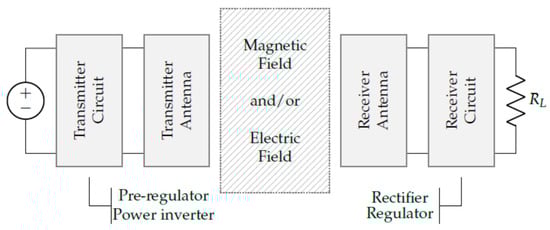
Figure 1. Structure of a “coupled” wireless power transfer system [32].
First, a power supply in combination with a transmitter circuit provides an amplified sinusoidal signal that can be controlled in both frequency and amplitude. For this purpose, a pre-regulator, a power inverter and a signal generator are required. Second, the transmitter antenna is coupled to the receiver antenna by means of an electric or magnetic field. Thirdly, the receiver circuit consists of an AC/DC conversion by means of a rectifier, smoothing capacitors and, optionally, a DC/DC converter [32].
The IPT technique (Induced Power Transmission) is based on the operation of a simple transformer in which a primary coil is powered by an alternate current. The current flowing in the primary coil creates a variable magnetic field in accordance with Ampere’s law [30] which induces an electromotive force according to Faraday’s induction law [30] in the secondary coil and thus transfers power to the load. In a transformer, the magnetic field is typically confined to a high-permeability core, but it also operates when the region between the primary and secondary coils is simply air [33]. Such systems are basically DC/DC converters built around a transformer whose windings are coupled in air. As the distance between the coils increases, the mutual inductance decreases rapidly resulting in a lower coupling factor. This significant reduction in coupling with increasing distance indicates that WPT via inductive coupling can only cover small distances.
IPT technology can be used for applications up to several kilowatts such as the charging of electric vehicles, it has an energy efficiency ranging from 50% [34] to 80% [33], it can use operating frequencies ranging from several kHz to a few MHz and it is a wireless power transfer technique for short distances ranging from a few millimeters to a few centimeters. However, this technology requires precise alignment for the charging path to achieve the highest level of efficiency.
The advantages of the IPT system include ease of implementation and operation. It is non-radiative and, due to its low transmission frequency, is considered safe for health. Furthermore, it does not present dangers induced by the possible presence of sparks and electrocution or short-circuit at any power level by virtue of the magnetic-type coupling. The main limitation of this mode of power transfer is that it performs well over considerably short distances. Increasing the transfer distance significantly reduces performance [35][36]. A key feature of the magnetic field is that it can transfer through any non-metallic and non-ferromagnetic material, such as plastic, glass, water, wood and, of course, air.
This method is based on the concept that two resonators with identical frequency can exchange energy efficiently with reciprocity [37]. Magnetic resonance coupling (MRC) can also be described as an improved IPT technology with compensation networks [34]. It uses resonance magnetic coupling to transfer energy from the transmitter to the receiver. Magnetic coupling in resonance can be generated by resonating each inductance of the primary and secondary coils with their respective parasitic capacitances. When the parasitic capacitance of the coils is inadequate to effect resonance at the desired frequency, an external capacitor is inserted in series or in parallel with the primary and secondary coil, respectively. Depending on the combination chosen, the compensation networks can assume the four topologies: series–series (SS), series–parallel (SP), parallel–series (PS) and parallel–parallel (PP) [30].
According to the available literature [33], the MRC-WPT technology has some advantages in terms of efficiency and transmission distance compared to the IPT for which the MRC-WPT is suitable in medium distance applications from tens of centimeters to a few meters while its operating frequency is usually much higher than in the IPT case: from a few MHz to several MHz.
The results of the studies reported in [33] show that the efficiency of the MRC-WPT can even exceed the traditional IPT system. In particular, the efficiency was higher than 80% at a distance of 50 cm and at 6.78 MHz. High operating frequencies and high-quality factors are the reasons behind the high-power transfer efficiency over long distances of the MRC-WPT method.
The resonant frequency changes as the distance and orientation between the coils varies, so for practical use an adaptive frequency tuning method is required to ensure that the highest possible transfer efficiency is maintained [38].
In [33], it is also highlighted that the IPT and MRC-WPT technologies use the same electromagnetic induction technique for power transfer; therefore, they can be merged together into a single technique despite their current distinctions. To confirm this, the research reported in [39], presents a comparative study between MRC-WPT and IPT by creating a model system for charging small batteries of implantable devices. This model behaves like a traditional IPT system when the system frequency is not the resonant one, while when it operates on a resonant frequency, it behaves like an MRC-WPT system.
The main difference between IPT and MRC-WPT is that the latter method is efficient even with low coupling factors and has less stringent alignment requirements, thus giving more spatial freedom to the positioning of the receiver with respect to the transmitter.
Energy can also be transferred through high-frequency electric fields using capacitive coupling. This method is referred to as Capacitive Power Transfer (CPT). In this case, the coupling between the receiving and transmitting parts is achieved through an electric field suitable for the efficient transfer of high electrical power. Usually, the capacitive coupling of a CPT system is represented as a pair of capacitors [40].
Unlike IPT and MRC-WPT, CPT does not generate eddy current losses in conductive objects and therefore introduces less fire risk. However, CPT suffers from a strong parasitic interaction with objects located in the environment. As a result, existing CPT solutions are targeted for low-power applications such as power and data coupling between integrated circuits or for power and data transmission to biomedical devices [41].
In recent years, high-power applications have become more viable thanks to recent studies on compensation circuits, suitable inverter stages and plate structures. New high-power applications such as underwater autonomous vehicles, railway applications, and electric vehicle charging or powering are some prominent examples. In particular, the dynamic charge capability of the CPT is considered promising [40].
Compared to magnetic induction methods, CPT has the following advantages [40].
-
Power losses due to eddy currents are minimal.
-
CPT is capable of wirelessly transferring energy through insulated metal objects.
-
Contrary to IPT, some misalignments do not significantly reduce power transfer.
-
Coupling is accomplished by simple conductive plates (e.g., aluminum or copper), which are less expensive and heavy than coils of wire. This simple configuration also facilitates high reliability and long life compared to IPT. Also, no special shape is required, enabling a versatile design.
-
CPT is less bulky than IPT; therefore, it can be implemented in integrated circuits.
-
Typically, less heat is produced than IPT with its high resistance coil windings.
-
Enables easy setup to charge multiple receivers from a single transmitter.
Despite the benefits it offers, CPT is not yet available on the market and research lags behind IPT. This is due to a few major drawbacks:
-
The low capacitance (and therefore the high impedance and low-power density) of the capacitive coupling;
-
High frequencies and voltages are needed, especially to cover greater distances; this implies high demands on the converter components;
-
High electric field between the primary and secondary sides imposes stringent operator safety regulations, e.g., object detection between the plates.
2.2. “Far-Field” Power Transmission Mechanisms
By adopting shorter wavelengths of electromagnetic radiation, typically in the microwave range, power transmission via radio waves become possible. A rectenna (rectifying antenna) can be used to convert microwave energy back into electricity [29]. A rectenna is a special type of receiving antenna that is used to convert electromagnetic energy into direct current electricity. A simple rectenna element consists of a dipole antenna with an RF diode connected between the dipole elements. The diode rectifies the alternating current induced in the antenna by the microwaves to produce unidirectional current which energizes a load connected across the diode.
In the case of electromagnetic radiation closest to the visible region of the spectrum (0.2 to 2 µm), power can be transmitted by converting electricity into a laser beam, which is received and focused on photovoltaic cells. This mechanism is generally known as “power beaming” because the power is projected towards a receiver which can convert it into electrical energy. Photovoltaic laser power converters optimized for the conversion of monochromatic light are applied to the receiver.
-
Wavefront propagation of collimated monochromatic light enables a small beam cross-sectional area for transmission over large distances; as a result, there is little or no loss of power as the distance from transmitter to receiver is increased.
-
Compact size: solid-state lasers fit into small products.
-
No radio frequency interference to existing radio communications such as Wi-Fi and cell phones.
-
Access control: only receivers hit by the laser receive power.
The disadvantages however include
-
Laser radiation is dangerous. Without a proper safety mechanism, even low-power levels can blind humans and other animals. High power levels can be harmful through localized spot heating.
-
Conversion between light and electricity is limited. Photovoltaic cells reach a maximum efficiency of 40–50%.
-
Absorption from the atmosphere as well as absorption and dispersion by clouds, fog, rain, etc., cause losses of up to 100%.
-
Requires direct line of sight to target.
2.3. Other Wireless Power Transfer Mechanisms
For the sake of completeness, other electrical power transfer methods are mentioned below which currently have a lower TRL than the previous ones and which have been reported in this document because, although they are not currently present with commercial products yet, they are undergoing a significant boost in terms of research and therefore could see an evolution in the near future that makes them applicable for practical uses. Power transfer by “Magneto–Dynamic Coupling”, MDC [42][43][44], power transfer by “electrodynamic coupling” [32][45], “Acoustic Power Transfer”, APT [32], Metal Surface Guided—Wireless Power Transfer, MSG-WPT [46][47].
2.4. Standards for Wireless Power Transfer
For many WPT methods there are no reference standards and for others the standards are in the process of being settled.
The Wireless Power Consortium (WPC) is an open standard development group with more than 400 member companies worldwide. It supplies a wide range of power transmission systems. WPC develops four standards: the Qi standard [48][49], the Ki Cordless Kitchen standard [50], the standard for light electric vehicles (LEV) and the industry standard [51]. Only the first is briefly described below.
The basic Qi standard is based on the IPT method. A two-way communication link is established using load modulation across the coils with Frequency-Shift Keying (FSK) modulation, thus eliminating the need for a supplemental radio system. The standard is developed for smartphones and other mobile devices and can transfer up to 30 W [48]. Future specification extension will provide up to 60 W to enable, for example, laptop charging [32]. The operating frequency is in the range from 87 to 205 kHz [48].
The power transfer system in the Qi specification is based on a single coil in the power transmitter with an outer diameter of 50 mm and a coil in the receiver with an outer diameter of 40 mm. In a typical use case, a receiver is placed on the top surface of a transmitter with its coils aligned. Ideally, the coils should be perfectly aligned for maximum power transfer, but coil misalignment of several millimeters is not a problem. The specification also features shutdown of the WPT when efficiency decreases due to, for example, misalignment and when foreign objects, such as metals, are detected which can cause safety problems [32][48].
All Qi receivers that have been integrated into various devices recently can be charged in the “inductive” and “resonant” modes. It is the transmitter (wireless charger) that defines the operating mode [49]. Most Qi transmitters use tight coupling between coils. In this configuration, the best results are obtained by operating the transmitter at a frequency slightly different from the resonant frequency of the Qi receiver. Off-resonance operation provides the maximum amount of power with the best efficiency. In this case, the system operates in the “inductive” mode [49]. As the distance between the receiver and transmitter increases, the magnetic coupling between the coils decreases. Systems with a low coupling factor must operate at the resonant frequency of the receiver. In this case, the system is in the “resonant” mode.
Loosely coupled systems compensate for the transfer of power over a greater distance with lower efficiency and higher electromagnetic emissions. Choosing these systems may be suitable in applications where it is impractical to have precisely aligned coils, but less suitable in applications with EMI or efficiency requirements.
The AirFuel Alliance is the merger of two previous standards groups, PMA (Power Matters Alliance) and A4WP (Alliance for Wireless Power). The organization focuses on creating wireless power standards based on magnetic resonance and radio frequency transmission [32]. The IEC 63028 Airfuel Alliance resonant baseline system specification describes the technical requirements, behaviors and interfaces used to ensure the interoperability of WPT systems with loosely coupled coils at the frequency of 6.78 MHz. The transmitter and receiver are called, respectively: Power Transmission Unit (PTU) and Power Receiver Unit (PRU).
2.5. Availability of Commercial Components
The following sections provide an overview of the integrated circuits and components currently on the market that can be integrated into custom products to create WPT systems. In some cases, there is “in principle” the possibility of implementing systems that work on proprietary methods but the information available is very infrequent, and often not of any practical value.
There are thousands of Qi-certified commercial products. For a reference list, you can look at the list of products on the Wireless Power Consortium (WPC) website [52]. Qi certification guarantees that devices (power receivers) and chargers (power transmitters) always work together regardless of the company that built them (interoperability) [53].
It is not possible to certify components such as coils, shields and integrated circuits. Compliance with the Qi specification can only be determined for products that are a fully functional Qi transmitter or Qi receiver. A product with components that have been successfully used in another Qi-certified product is not automatically compliant. The use of materials, different housings, different positions of coils and shields, even differences in firmware can interfere with wireless power transfer. Integrated circuit manufacturers usually demonstrate the suitability of their product by certifying a demo product, the so-called “Evaluation Module”. The products that use this IC must then be tested to verify their conformity: they are not to be considered automatically compliant [54].
Infineon’s (Neubiberg, Germany) WLC1115 is a highly integrated, Qi-compliant, fully configurable 15W transmitter control IC for wireless charging solutions that supports a wide range of input voltages from 4.5 V to 24 V DC. The WLC1115-based Extended Power Profile (EPP) transmitter solution using the other IC also from Infineon OPTIGA Trust Charge, meets the requirements specified in the Qi standard v1.3.2. Combined with Infineon’s comprehensive offering for USB-C chargers and broad MOSFET portfolio, the WLC1115 solution offers a complete product package that can meet regulatory and compliance requirements. This combination of hardware devices is also accompanied by software tools that support Qi v1.3.2 charging protocols [55]. The chip is marketed by Mouser [56].
ST Microelectronics’ (Geneva, Switzerland) STWLC68 is an integrated wireless power receiver suitable for portable applications and capable of handling up to 5 W of output power. The chip has been designed to support the Qi 1.2.4 specification for the IPT Base Power Profile (BPP) communication protocol [57].
ST Microelectronics’ STWLC38 is an integrated wireless power receiver suitable for smartphones and can provide up to 15 W of power output. The chip was designed to support Qi specification 1.3 for IPT, 5 W BPP and 15 W EPP communication protocol. STWLC38 is also able to operate in Tx mode to transmit power to charge other devices. In this mode, the device can deliver up to 5 W of power output [58].
ST Microelectronics’ STWBC2-HP is a digital controller specifically dedicated to the design of Qi-certified wireless power transmitter applications [59].
ST Microelectronics’ STWLC98 is a highly integrated wireless power receiver suitable for applications requiring up to 70 W output power [60]. The chip was designed to support Qi specifications 1.2.4 and 1.3 for the IPT communication protocol with EPP as well as the proprietary ST Super Charge (STSC) protocol for fast charging. The STWLC98 is the heart of the receiver whose counterpart sees the STWBC2-HP chip as a transmitter controller in a pair that can transfer up to 70 W with high efficiency [61].
Renesas Electronics (Tokyo, Japan) is a member of the Wireless Power Consortium (WPC) and, among other things, develops integrated circuits for wireless power transfer and Qi-certified reference designs. Renesas also produces reference kits for Tx circuits [62] and Rx [63] Qi-certified wireless power supplies that include everything needed to streamline custom application development and minimize time to market.
TDK (Tokyo, Japan) also offers a line of components for the creation of wireless power transfer systems [64]. In particular, TDK offers coils (antennas) for transmitters [65] and for receivers [66].
The availability of commercial components for the realization of wireless power transfer systems of the MRC type is very scarce. Such systems must be designed ad hoc. Some guidelines for their sizing can be found on the Airfuel Alliance website [67]. Some demo kits using this transfer mechanism can be found in [68][69].
Powercast (Pittsburgh (PA), United States) is a pioneer and leader in long-range wireless charging technology using RF energy. Since 2003, the company has provided solutions that combine its FCC-approved transmitters and receivers to enable automatic charging of multiple devices over the air, without the need for direct line of sight.
A transmitter sends RF energy over the air to a receiver chip embedded in a device, which converts it to DC to recharge batteries or directly power the device. This means that enabled devices automatically charge when they are within range of a power transmitter. The system is intelligent, configurable and controllable, it can activate automatically when the devices need to be charged and switch off when recharging is complete, or it can supply energy continuously or on a programmed basis. The transmitters are qualified for the US and Canadian markets.
The PowerSpot TX91503 transmitter transmits power over radio waves in the 915 MHz ISM band without a license [70]. Designed for use with Powerharvester receivers, the transmitter and receivers work as an end-to-end system to wirelessly charge batteries for consumer applications [71]. In its catalog, Powercast also offers development kits and evaluation boards that should enable the creation of simple and fast tests and prototypes with RF-based wireless power technology [72].
Powercast products are marketed by online distributors Mouser, Digi-Key and Arrow.
A technology that seems promising is the one proposed by OSSIA Real Wireless Power (Redmond (WA), United States) but the information available is very little. So far, no information on precise power ratings and distances has been released. The Cota technology of OSSIA Real Wireless Power [31][73] creates an environment that keeps any number of digital devices powered at all times. The Cota Power receiver, built into any device, initiates the “conversation” by sending out a beacon signal to find a Cota Power transmitter. The transmitter then sends power back the same path. This “talk” between the receiver and transmitter happens 100 times per second to send power to the remote devices even if they’re in motion.
Cota is a smart antenna system designed to safely charge multiple remote devices without users’ intervention at distances up to 10 m. There are three main components of the Cota platform: the Cota receiver, the Cota transmitter and the Cota cloud. The Cota receiver is based on a 3 mm × 3 mm integrated circuit, which can be integrated into any product. It is capable of receiving up to 4 watts of RF input power from the Cota transmitter. The receiver sends a low-power 2.4 GHz radio (beacon) signal to the transmitter which uses smart antennas to send the feed signal back along the same path, either a direct or an indirect one. The signal will bounce off solid objects and around any obstacles, following the same path used by the beacon to reach the transmitter. Any type of antenna can be used for the receiver. Multiple transmitters can work together to extend the power transmission range to distances much greater than 10 m. Cota Cloud helps activate, manage and monitor all connected devices, including deciding which devices need to be charged the most. The Cota wireless power system can also be retrofitted to battery-operated devices through the adoption of the “Cota Forever battery” that fits the footprint of current AA-type batteries [74].
References
- Balota, J.E.; Pattinson, C.; Kor, A.L. Wireless Personal Area Networks—A Survey of Low-Rate and Low Power Network Technologies. In Proceedings of the Wireless Congress on Sustainable Technologies, Cambridge, UK, 11–14 December 2017; pp. 68–73.
- CCSDS 880.0-G-3; Wireless Network Communications Overview for Space Mission Operations. 3rd ed. CCSDS: Washington, DC, USA, 2017. Available online: https://public.ccsds.org/Pubs/880x0g3.pdf (accessed on 10 January 2024).
- Rondón, R.; Gidlund, M.; Landernäs, K. Evaluating Bluetooth Low Energy Suitability for Time-Critical Industrial IoT Applications. Int. J. Wirel. Inf. Netw. 2017, 24, 278–290.
- Seferagić, A.; Famaey, J.; De Poorter, E.; Hoebeke, J. Survey on Wireless Technology Trade-Offs for the Industrial Internet of Things. Sensors 2020, 20, 488.
- Park, P.; Di Marco, P.; Nah, J.; Fischione, C. Wireless Avionics Intra-Communications: A Survey of Benefits, Challenges, and Solutions. IEEE Internet Things J. 2021, 8, 7745–7767.
- El Gholami, K.; Maleh, Y.; Fatani, I.F.-E. The IEEE 802.15.4 Standard in Industrial Applications: A Survey. J. Theor. Appl. Inf. Technol. 2021, 99, 1–17. Available online: http://www.jatit.org/volumes/Vol99No15/13Vol99No15.pdf (accessed on 10 January 2024).
- Kurunathan, H.; Severino, R.; Koubaa, A.; Tovar, E. IEEE 802.15.4e in a Nutshell: Survey and Performance Evaluation. IEEE Commun. Surv. Tutor 2018, 20, 1989–2010.
- Muñoz, J.; Riou, E.; Vilajosana, X.; Muhlethaler, P.; Watteyne, T. Overview of IEEE802.15.4g OFDM and its applicability to smart building applications. In Proceedings of the 2018 Wireless Days (WD), Dubai, United Arab Emirates, 3–5 April 2018.
- Coppens, D.; Shahid, A.; Lemey, S.; Van Herbruggen, B.; Marshall, C.; De Poorter, E. An Overview of UWB Standards and Organizations (IEEE 802.15.4, FiRa, Apple): Interoperability Aspects and Future Research Directions. IEEE Access 2022, 10, 70219–70241.
- ZigBee Alliance. ZigBee Specification. Revision 22 1.0, April 2017. Available online: https://csa-iot.org/it/risorsa-per-sviluppatori/richiesta-di-download-delle-specifiche/ (accessed on 10 January 2024).
- Wang, Q.; Jiang, J. Comparative Examination on Architecture and Protocol of Industrial Wireless Sensor Network Standards. IEEE Commun. Surv. Tutor. 2016, 18, 2197–2219.
- Das Neves Valadão, Y.; Künzel, G.; Müller, I.; Pereira, C.E. Industrial Wireless Automation: Overview and Evolution of WIA-PA. IFAC-Pap. 2018, 51, 175–180.
- IEEE Std 802.15.3-2003; Part 15.3: Wireless Medium Access Control (MAC) and Physical Layer (PHY) Specifications for High Rate Wireless Personal Area Networks (WPANs). IEEE Computer Society: New York, NY, USA, 29 September 2003. Available online: http://magrawal.myweb.usf.edu/dcom/Ch8_802.15.3-2003.pdf (accessed on 12 July 2023).
- Karunakar, K.; Chitneni, A. A Comparative Study of Wireless Protocols: Bluetooth, UWB, ZigBee, and Wi-Fi. Adv. Electron. Electr. Eng. 2014, 4, 655–662.
- International Standard ISO/IEC/IEEE 8802-15-3:2017(E); Information Technology—Telecommunications and Information Exchange between Systems—Local and Metropolitan Area Networks—Specific Requirements—Part 15-3: High Data Rate Wireless Multi-Media Networks. 2016. Available online: https://www.iso.org/standard/72248.html (accessed on 10 January 2024).
- IEEE 802.15.3d-2017; IEEE Standard for High Data Rate Wireless Multi-Media Networks Amendment 2: 100 Gb/s Wireless Switched Point-to-Point Physical Layer. Available online: https://standards.ieee.org/ieee/802.15.3d/6648/ (accessed on 10 January 2024).
- IEEE 802.15.3e-2017; IEEE Standard for High Data Rate Wireless Multi-Media Networks Amendment 1: High-Rate Close Proximity Point-to-Point Communications. Available online: https://standards.ieee.org/ieee/802.15.3e/6131/ (accessed on 10 January 2024).
- IEEE 802.15.3f-2017; IEEE Standard for High Data Rate Wireless Multi-Media Networks Amendment 3: Extending the Physical Layer (PHY) Specification for Millimeter Wave to Operate from 57.0 GHz to 71 GHz. Available online: https://standards.ieee.org/ieee/802.15.3f/7011/ (accessed on 10 January 2024).
- Zappaterra, L.; Sayrafian-Pour, K. Simulation Model for the IEEE 802.15.3/3b WPAN Standard. In Proceedings of the OPTNETWORK 2010, Washington DC, USA, 30 August–2 September 2010; Available online: https://tsapps.nist.gov/publication/get_pdf.cfm?pub_id=906075 (accessed on 10 January 2024).
- Kwak, K.S.; Ullah, S.; Ullah, N. An overview of IEEE 802.15.6 standard. In Proceedings of the 2010 3rd International Symposium on Applied Sciences in Biomedical and Communication Technologies (ISABEL 2010), Roma, Italy, 7–10 November 2010.
- Huang, R.; Nie, Z.; Duan, C.; Liu, Y.; Jia, L.; Wang, L. Analysis and Comparison of the IEEE 802.15.4 and 802.15.6 Wireless Standards Based on MAC Layer. In HIS 2015—Health Information Science; Yin, X., Ho, K., Zeng, D., Aickelin, U., Zhou, R., Wang, H., Eds.; Springer: Cham, Switzerland, 2015; Volume 9085.
- Ullah, S.; Mohaisen, M.; Alnuem, M.A. A Review of IEEE 802.15.6 MAC, PHY, and Security Specifications. Int. J. Distrib. Sens. Netw. 2013, 9, 950704.
- CCSDS 883.0-B-1; Spacecraft Onboard Interface Services-High Data Rate 3GPP and Wi-Fi Local Area Communications. 1st ed. CCSDS: Washington, DC, USA, 2022. Available online: https://public.ccsds.org/Pubs/883x0b1.pdf (accessed on 10 January 2024).
- Cordeiro, C. Intel. Next-Generation Wi-Fi—Wi-Fi 7 and Beyond” July 2020. Available online: https://www.intel.com/content/dam/www/public/us/en/documents/pdf/wi-fi-7-and-beyond.pdf (accessed on 12 July 2023).
- Sun, W.; Choi, M.; Choi, S. IEEE 802.11ah: A Long Range 802.11 WLAN at Sub 1 GHz. J. ICT Stand. 2013, 1, 83–108.
- Bankov, D.; Khorov, E.; Lyakhov, A.; Stepanova, E. Clock Drift Impact on Target Wake Time in IEEE 802.11ax/ah Networks. In Proceedings of the 2018 Engineering and Telecommunication (EnT-MIPT), Moscow, Russia, 15–16 November 2018; pp. 30–34.
- Adame, T.; Carrascosa-Zamacois, M.; Bellalta, B. Time-Sensitive Networking in IEEE 802.11be: On the Way to Low-Latency WiFi 7. Sensors 2021, 21, 4954.
- Drobczyk, M.; Lübken, A. Wireless intra-spacecraft communication with inspaWSN protocol stack based on IR-UWB. In Proceedings of the 12th IAA Symposium on Small Satellites for Earth Observation, Berlin, Germany, 6–10 May 2019; Available online: https://iaaspace.org/wp-content/uploads/iaa/Scientific%20Activity/conf/sseo2021/berlin2019proceedings.pdf (accessed on 10 January 2024).
- Wireless Power Transfer. Available online: https://en.wikipedia.org/wiki/Wireless_power_transfer (accessed on 12 July 2023).
- Houran, M.A.; Yang, X.; Chen, W. Magnetically Coupled Resonance WPT: Review of Compensation Topologies, Resonator Structures with Misalignment, and EMI Diagnostics. Electronics 2018, 7, 296.
- Lu, X.; Wang, P.D.; Niyato, D.; In Kim, D.; Han, Z. Wireless Charging Technologies: Fundamentals, Standards, and Network Applications. IEEE Commun. Surv. Tutor. 2016, 18, 1413–1452.
- Van Mulders, J.; Delabie, D.; Lecluyse, C.; Buyle, C.; Callebaut, G.; Van der Perre, L.; De Strycker, L. Wireless Power Transfer: Systems, Circuits, Standards, and Use Cases. Sensors 2022, 22, 5573.
- Rehman, M.; Nallagownden, P.; Baharudin, Z. A Review Of Wireless Power Transfer System Using Inductive And Resonant Coupling. J. Ind. Technol. 2018, 26, 1–24.
- Shevchenko, V.; Husev, O.; Strzelecki, R.; Pakhaliuk, B.; Poliakov, N.; Natalia, S. Compensation Topologies in IPT Systems: Standards, Requirements, Classification, Analysis, Comparison and Application. IEEE Access 2019, 7, 120559–120580.
- Sidiku, M.B.; Eronu, E.M.; Ashigwuike, E.C. A Review on Wireless Power Transfer: Concepts, Implementations, Challenges, and Mitigation Schemes. Niger. J. Technol. 2020, 39, 1206–1215.
- Wei, X.; Wang, Z.; Dai, H. A Critical Review of Wireless Power Transfer via Strongly Coupled Magnetic Resonances. Energies 2014, 7, 4316–4341.
- Kiani, M.; Ghovanloo, M. The Circuit Theory Behind Coupled-Mode Magnetic Resonance-Based Wireless Power Transmission. IEEE Trans Circuits Syst. 2012, 59, 2065–2074.
- Sample, A.P.; Meyer, D.A.; Smith, J.R. Analysis, Experimental Results, and Range Adaptation of Magnetically Coupled Resonators for Wireless Power Transfer. IEEE Trans. Ind. Electron. 2011, 58, 544–554.
- Ho, S.L.; Wang, J.; Fu, W.N.; Sun, M. A Comparative Study Between Novel Witricity and Traditional Inductive Magnetic Coupling in Wireless Charging. IEEE Trans. 2011, 47, 1522–1525.
- Lecluyse, C.; Minnaert, B.; Kleemann, M. A Review of the Current State of Technology of Capacitive Wireless Power Transfer. Energies 2021, 14, 5862.
- Song, M.; Jayathurathnage, P.; Zanganeh, E.; Krasikova, M.; Smirnov, P. Up-And-Coming Physical Concepts of Wireless Power Transfer. arXiv 2021, arXiv:2107.14086v1.
- Li, W. High Efficiency Wireless Power Transmission at Low Frequency Using Permanent Magnet Coupling. Master’s Thesis, University of British Columbia, Vancouver, Canada, 2009. Available online: https://open.library.ubc.ca/soa/cIRcle/collections/ubctheses/24/items/1.0067661 (accessed on 10 January 2024).
- UBC Wireless Power Transfer Technology USES magneto-Dynamic Coupling Rather Than Inductive Technology. Available online: https://www.greencarcongress.com/2012/11/ubcmdc-20121124.html (accessed on 12 July 2023).
- ELIX Wireless & Zongshen Partner on Wireless Chargers for China and NA.; Magneto-Dynamic Coupling (MDC). Available online: https://www.greencarcongress.com/2016/09/20160921-elix.html (accessed on 12 July 2023).
- Challa, V.R.; Mur-Miranda, J.O.; Arnold, D.P. Wireless power transmission to an electromechanical receiver using low-frequency magnetic fields. Smart Mater. Struct. 2012, 21, 115017.
- Oruganti, S.K.; Liu, F.; Paul, D.; Liu, J.; Malik, J.; Feng, K.; Kim, H.; Liang, Y.; Thundat, T.; Bien, F. Experimental Realization of Zenneck Type Wave-based Non-Radiative, Non-Coupled Wireless Power Transmission. Sci Rep 2020, 10, 925.
- Bien, F.; Park, W.; Lee, B.; Byun, G. Metal Surface Guided-Wireless Power Transfer System for Portable Applications with Multiple Receivers. IEEE Access 2021, 9, 78724–78734.
- WPC—Qi Specification, V1.3. Available online: https://www.wirelesspowerconsortium.com/knowledge-base/specifications/ (accessed on 12 July 2023).
- WPC—A Qi Wireless Charger: Resonant as well as Inductive. Available online: https://www.wirelesspowerconsortium.com/knowledge-base/magnetic-induction-technology/resonance/qi-wireless-charger-resonant-as-well-as-inductive.html (accessed on 12 July 2023).
- WPC—KI Cordless Kitchen Standard. Available online: https://www.wirelesspowerconsortium.com/kitchen/ (accessed on 12 July 2023).
- Wireless Power Consortium (WPC). Available online: https://www.wirelesspowerconsortium.com/ (accessed on 12 July 2023).
- Wireless Power Consortium—Products. Available online: https://www.wirelesspowerconsortium.com/products (accessed on 12 July 2023).
- Qi Certified Products—Safe and Reliable Wireless Charging. Available online: https://www.wirelesspowerconsortium.com/knowledge-base/testing-and-certification/qi-certified-products.html (accessed on 12 July 2023).
- Qi Components and Subsystems. Available online: https://www.wirelesspowerconsortium.com/knowledge-base/testing-and-certification/qi-components-and-subsystems.html (accessed on 12 July 2023).
- Infineon WLC1115-68LQXQ. Available online: https://www.infineon.com/cms/en/product/power/wireless-charging-ics/wlc1115-68lqxq/ (accessed on 12 July 2023).
- Mouser Catalog, Infineon WLC1115-68LQXQ. Available online: https://eu.mouser.com/ProductDetail/Infineon-Cypress/WLC1115-68LQXQ?qs=4ASt3YYao0VGjx2nXvg4iw%3D%3D (accessed on 12 July 2023).
- Qi-Compliant Inductive Wireless Power Receiver for 5W Applications STWLC68. Available online: https://www.st.com/content/ccc/resource/technical/document/datasheet/group3/5b/66/a7/45/0a/e6/4f/6e/DM00658688/files/DM00658688.pdf/jcr:content/translations/en.DM00658688.pdf (accessed on 12 July 2023).
- Qi-Compliant Dual Mode Wireless Power Receiver for up to 15W Applications STWLC38. Available online: https://www.st.com/content/ccc/resource/technical/document/datasheet/group3/92/9e/21/71/9b/54/4e/22/DM00912846/files/DM00912846.pdf/jcr:content/translations/en.DM00912846.pdf (accessed on 12 July 2023).
- Digital Controller for Wireless Battery Charger Transmitters STWBC2-HP. Available online: https://www.st.com/content/ccc/resource/technical/document/datasheet/group3/d8/6b/2a/26/d3/55/41/88/DM00822698/files/DM00822698.pdf/jcr:content/translations/en.DM00822698.pdf (accessed on 12 July 2023).
- Qi-Compliant Inductive Wireless Power Receiver for 70W applications STWLC98. Available online: https://www.st.com/content/ccc/resource/technical/document/data_brief/group3/c9/6d/ba/30/b0/08/4c/d0/DM00815066/files/DM00815066.pdf/jcr:content/translations/en.DM00815066.pdf (accessed on 12 July 2023).
- STMicroelectronics Boosts Wireless Charging Speed, Efficiency, and Flexibility with 70W High-Power Chipsets. Available online: https://newsroom.st.com/media-center/press-item.html/n4390.html# (accessed on 12 July 2023).
- Qi Compliant Wireless Power Transmitter ICs. Available online: https://www.renesas.com/eu/en/products/power-power-management/wireless-power/wireless-power-transmitters (accessed on 12 July 2023).
- Wireless Power Receiver ICs. Available online: https://www.renesas.com/eu/en/products/power-power-management/wireless-power/wireless-power-receivers (accessed on 12 July 2023).
- TDK, WPT Product Lineup. Available online: https://product.tdk.com/en/products/wireless-charge/index.html (accessed on 12 July 2023).
- TDK Tx Coil Units and Modules. Available online: https://product.tdk.com/en/search/wireless-charge/wireless-charge/tx-coil-module/catalog (accessed on 12 July 2023).
- TDK Rx Coil Units and Modules. Available online: https://product.tdk.com/en/search/wireless-charge/wireless-charge/rx-coil-module/catalog (accessed on 12 July 2023).
- Tools to Integrate AirFuel Resonant in Your Product. Available online: https://airfuel.org/tools-to-integrate-airfuel-resonant-in-your-product/ (accessed on 12 July 2023).
- Complete AirFuel Alliance Compatible Wireless Power Demo Kit. Available online: https://eepower.com/new-industry-products/complete-airfuel-alliance-compatible-wireless-power-demo-kit/ (accessed on 12 July 2023).
- EPC9129—Wireless Power Demonstration System. Available online: https://epc-co.com/epc/products/demo-boards/epc9129 (accessed on 12 July 2023).
- Powercast—PowerSpot. Available online: https://www.powercastco.com/products/powerspot/ (accessed on 12 July 2023).
- Powercast—Powerharvester Receiver Chips & Modules. Available online: https://www.powercastco.com/receivers/ (accessed on 12 July 2023).
- Powercast—Development Tools. Available online: https://www.powercastco.com/development-kits/#P2110-EVAL-01 (accessed on 12 July 2023).
- OSSIA Real Wireless Power—COTA. Available online: https://www.ossia.com/cota/ (accessed on 12 July 2023).
- Wireless Power Technology Will Lead to Smaller IoT Devices—14 September 2021. Available online: https://www.powersystemsdesign.com/articles/wireless-power-technology-will-lead-to-smaller-iot-devices/149/18265 (accessed on 12 July 2023).
More
Information
Subjects:
Engineering, Aerospace
Contributors
MDPI registered users' name will be linked to their SciProfiles pages. To register with us, please refer to https://encyclopedia.pub/register
:
View Times:
1.3K
Revisions:
2 times
(View History)
Update Date:
18 Feb 2024
Table of Contents


Notice
You are not a member of the advisory board for this topic. If you want to update advisory board member profile, please contact office@encyclopedia.pub.
OK
Confirm
Only members of the Encyclopedia advisory board for this topic are allowed to note entries. Would you like to become an advisory board member of the Encyclopedia?
Yes
No
${ textCharacter }/${ maxCharacter }
Submit
Cancel
Back
Comments
${ item }
|
${ item.createdUser.fullName }
${ item.createdAt }
${ item.vote }
${ item.reply }
Delete
${ reply.createdUser.fullName }
${ reply.createdAt }
${ reply.vote }
Delete
There is no reply to this comment~
${ item.replyTextCharacter }/${ item.replyMaxCharacter }
Submit
Cancel
More
No more~
There is no comment~
${ textCharacter }/${ maxCharacter }
Submit
Cancel
${ selectedItem.replyTextCharacter }/${ selectedItem.replyMaxCharacter }
Submit
Cancel
Confirm
Are you sure to Delete?
Yes
No