Your browser does not fully support modern features. Please upgrade for a smoother experience.
Submitted Successfully!
 +1 credit
Thank you for your contribution! You can also upload a video entry or images related to this topic.
For video creation, please contact our Academic Video Service.
| Version | Summary | Created by | Modification | Content Size | Created at | Operation |
|---|---|---|---|---|---|---|
| 1 | Pedro Miguel Andrade | -- | 1831 | 2024-02-08 18:28:14 | | | |
| 2 | Camila Xu | Meta information modification | 1831 | 2024-02-09 01:59:19 | | |
Video Upload Options
We provide professional Academic Video Service to translate complex research into visually appealing presentations. Would you like to try it?
Cite
If you have any further questions, please contact Encyclopedia Editorial Office.
Andrade, P.; Laadjal, K.; Alcaso, A.N.; Cardoso, A.J.M. Fuel Cells Technologies. Encyclopedia. Available online: https://encyclopedia.pub/entry/54946 (accessed on 26 July 2026).
Andrade P, Laadjal K, Alcaso AN, Cardoso AJM. Fuel Cells Technologies. Encyclopedia. Available at: https://encyclopedia.pub/entry/54946. Accessed July 26, 2026.
Andrade, Pedro, Khaled Laadjal, Adérito Neto Alcaso, Antonio J. Marques Cardoso. "Fuel Cells Technologies" Encyclopedia, https://encyclopedia.pub/entry/54946 (accessed July 26, 2026).
Andrade, P., Laadjal, K., Alcaso, A.N., & Cardoso, A.J.M. (2024, February 08). Fuel Cells Technologies. In Encyclopedia. https://encyclopedia.pub/entry/54946
Andrade, Pedro, et al. "Fuel Cells Technologies." Encyclopedia. Web. 08 February, 2024.
Copy Citation
The complexity of Fuel Cell (FC) systems demands a profound and sustained understanding of the various phenomena occurring inside of it. Thus far, FCs, especially Proton Exchange Membrane Fuel Cells (PEMFCs), have been recognized as being among the most promising technologies for reducing Green House Gas (GHG) emissions because they can convert the chemical energy bonded to hydrogen and oxygen into electricity and heat.
fuel cell system
proton exchange membrane
open-cathode fuel cells
1. Introduction
Climate change has been raising different questions and concerns with scientists and researchers around the world. It is caused by the increase in Green House Gas (GHG) emissions, such as carbon dioxide, which are released during the process of burning fossil fuel to produce electric energy. Nonetheless, most European countries are starting to have a significant quota of Renewable Energies [1]. Even though the percentage of renewable energy is increasing, another problem related to energy storage arises. This problem is related to the intermittent nature of renewable sources, which are dependent on external, uncontrollable factors, such as the sun and the wind, generating a gap between the available energy and its final use. Therefore, storing the excess produced energy is paramount to eliminating the intermittent nature of renewable energies [2]. Among other solutions, hydrogen storage is being intensively researched to work as an energy vector, as illustrated in Figure 1, for future direct conversion to electricity when demanded [1][3].
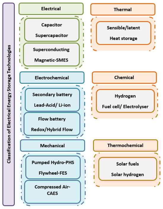
Figure 1. General classification of electrical energy storage technologies.
Converting the energy stored in hydrogen back to electricity requires an electrochemical device, such as an FC, which chemically converts the energy present into two reactants, in this case, hydrogen and oxygen, into electricity and heat [4]. Despite the simple theoretical process, the overall composition of the system is still dependent on expensive and rare materials, such as gold and platinum [4]. So, to ensure that the lifetime expectancy increases and the FC system is reliable, a deep understanding of how it operates under different conditions is required; this includes identifying ways to prevent and address any potential issues, like faults [5]. Thereafter, the analysis of fault diagnosis plays a crucial role in ensuring the stable operation and efficient output of FC systems. In recent years, numerous scholars have delved into this area to enhance accuracy and reliability. There are primarily two types of approaches: model-based methods (both qualitative and quantitative) and data-driven methods. In the model-based approach, an accurate mathematical model is developed based on the internal mechanisms of FC system operation [6]. Subsequently, residual vectors are utilized as features for statistical analysis to extract fault information embedded in the residual sequence. This process enables the detection of abnormal situations within the system, but existing fault diagnosis technology falls short in predicting the future degradation trend of FC systems. If the degradation of FCs could be estimated before a complete failure, maintenance personnel would have ample time to devise maintenance plans and replace components proactively. This proactive approach could significantly reduce repair and maintenance costs and prevent the unscheduled downtime of FC systems [7][8]. Faults, or failure modes, have been well established in the literature [9], and some reviews on fault diagnosis have been summarised in [10][11]. For example, in both [12][13], several tests for single and multi-cells under the influence of constant and dynamic loads have been reviewed and analyzed. It has been concluded that ensuring a specific relationship between failure modes and a particular signal, referenced as an indicator, requires an extensive amount of data under various operation conditions. However, there is an evident relationship between the cathode pressure drop and cathode flooding. Moreover, ref. [14] presented different model and non-model diagnosis methods for FC, while ref. [15] focused more on non-model-based diagnostics approaches. The conclusion drawn was that, when compared to model-based techniques, non-model-based approaches require a larger dataset of both normal and faulty conditions. Nevertheless, they are considered a prominent method for FC fault diagnosis due to their simplicity, flexibility, and ability to handle system uncertainties.
2. Fuel Cells Technologies
Fuel cells can be classified based on several factors. First, they can be categorized depending on the type of electrolyte separating the electrodes they use, which can be either alkaline or acidic. Second, a more common classification is through the operating temperature; therefore, they are referred to as a High-Temperature Fuel Cell (HT-FC) or a Low-Temperature Fuel Cell (LT-FC).
Table 1 outlines the typical characteristics of the different types of FCs, organized by their operating temperatures. The efficiency of FCs is influenced by the choice of electrolytes, catalysts, and operating temperature. Different FCs and their applications are illustrated in Table 1.
Table 1. An overview of the different materials for different types of FCs.
| Type | Anode | Cathode | Electrolyte | Temperature (°C) | Application |
|---|---|---|---|---|---|
| Molten Carbonate Fuel Cells (MCFC) | Ni | NiO | Molten Li2CO3 in LiAlO−2 | 550–700 (HT-FC) |
Energy Storage/Cogeneration [16] |
| Alkaline Fuel Cell (AFC) |
Carbon (C)/Platinum (Pt) catalyst | Carbon (C)/Platinum (Pt) catalyst | Aqueous KOH | Ambient–250 (LT-FC) |
Space Exploration [17] |
| Phosphoric Acid Fuel Cell (PAFC) |
C/Pt catalyst | C/Pt catalyst | Phosphoric acid in SiC matrix | 150–220 (LT-FC) |
Stationary Power [18] |
| Direct Methanol Fuel Cell (DMFC) |
C/Pt catalyst | C/Pt catalyst | Acidic Polymer | 60–90 (LT-FC) |
Portable Applications [19] |
| Solid Oxide Fuel Cell (SOFC) |
Ni-YSZ | LSM* Perovskite | YSZ* | 600–1000 (HT-FC) |
Stationary and Distributed Power [20] |
| Polymer Electrolyte Membrane Fuel Cell (PEMFC) |
C/Pt catalyst | C/Pt catalyst | Acidic Polymer | Ambient–90 (LT-FC) |
Stationary, Portable and Vehicle Applications [21] |
Note: YSZ* = Yttria-stabilized zirconia. LSM* = Stronia-dopped lanthanum manganite.
MCFCs find applications in energy storage [22][23][24][25][26][27]. Operating efficiently at 560 °C, MCFCs generate excess heat, which can be utilized in cogeneration processes. AFCs were the first FC model to be used by NASA in the first space exploration missions because of their vast temperature range and high efficiency, which were critical aspects at the time. PAFCs represent one of the first widely commercialized fuel cell technologies in the mid-1970s and offered a reliable solution for stationary applications at the time [18][22][28][29]. Due to their moderate operating temperature, PAFCs boast high efficiency and offer a wide range of reactant possibilities. However, they suffer from drawbacks such as poor power density, limited lifespan, and high production costs, which hinder their progress.
DMFCs undergo methanol oxidation to convert chemical energy into electrical energy [30]. Regarded as one of the most advanced fuel cells in terms of performance and user convenience, the DMFC is being explored as a potential alternative to traditional batteries in portable systems. These fuel cells fall into the category of low-temperature fuel cells based on polymer membranes; however, they have a high environmental impact since carbon dioxide is one of the byproducts. Moreover, another drawback of DMFC is the possibility of methanol crossover through the membrane, causing the efficiency to decrease [31]. SOFCs are the most suitable for high-power applications and large-scale centralized electric energy production. Unlike other FCs, they do not require expensive and rare materials for the electrodes and are less prone to Carbon Monoxide (CO) poisoning; however, a higher start-up time to reach the temperature range is required [4].
The PEMFC was initially developed for the Gemini spacecraft. In this design, a proton-conducting polymer membrane serves as the electrolyte, with electrodes constructed on thin layers on either surface. In certain aspects, the electrolyte resembles the plasticized electrolyte found in lithium-ion cells, comprising a liquid electrolyte trapped within a polymer matrix component [32]. Due to their diverse applications and the emission of residual GHG, PEMFCs have become a focal point for researchers seeking enhancements. Despite sharing a similar working principle with different types, PEMFCs consist of distinct components, as depicted in Figure 2. The negatively charged electrode, known as the anode, and its counterpart, the cathode, are separated by layers including a Gas Diffusion Layer (GDL). The GDL efficiently disperses reactants from the inlet to the catalyst layer, where crucial chemical reactions take place. On the anode side, hydrogen undergoes oxidation, and the resulting hydrogen protons move across the protonic membrane to the cathode, while electrons flow through the external circuit. At the cathode, oxygen is reduced by reacting with protons and electrons, resulting in the production of water and heat [4].
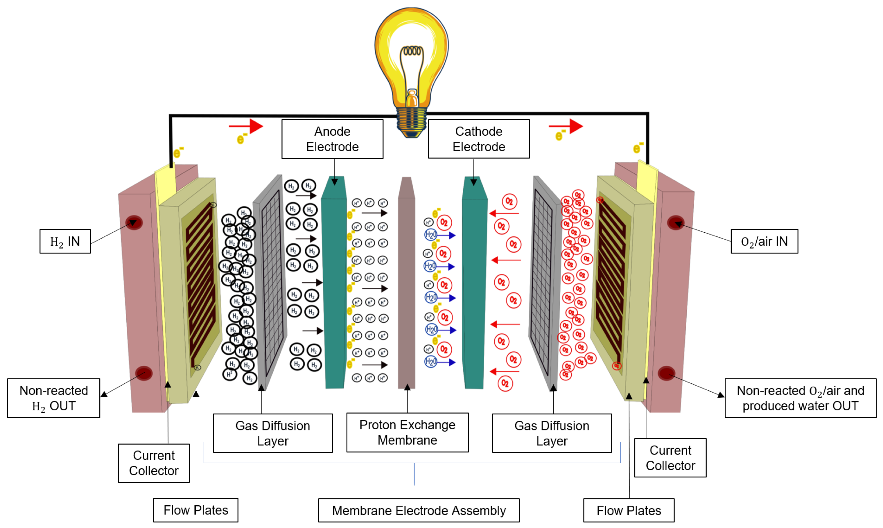
Figure 2. Fuel Cell composition.
Another crucial characteristic of fuel cells is the polarization curve, depicting the relationship between fuel cell voltage and current under various loads. Figure 3 provides a general representation where three distinct zones are identified. The first zone, occurring at low power densities, is commonly referred to as activation polarization. This zone illustrates the energy barrier that must be overcome to initiate the electrochemical reaction at the electrode. Next, the ohmic zone exhibits a linear relationship between voltage and current. The slope in this zone is determined by the inherent resistance that conductors pose to the passage of electrical charges. Finally, the concentration zone or mass transport zone is characterized by a sudden voltage drop. This drop is attributed to the fuel cell’s inability to expel reaction products, indicating that the concentration of reaction products surpasses that of the reactants [4]. The zones mentioned in the text signify the losses that cannot be reversed. The relationship between voltage and current is determined chemically by comparing the open-circuit voltage (a reversible loss), also known as the Nernst voltage, with the irreversible losses mentioned earlier.
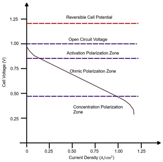
Figure 3. Typical Fuel Cell polarization curve.
A further consideration for PEMFCs is the reactant feeding configuration. In educational stack models, a common setup is the cathode-close configuration, where both pure hydrogen and oxygen supplies are required. Much of the presented research focuses on this model due to its cost-effectiveness, ability to function as an electrolyzer producing necessary gases, and its suitability for experimenting with various Membrane Electrode Assembly (MEA) materials. For higher stack power, PEMFCs adopt an open cathode configuration, using atmospheric air as the oxygen source. This configuration simplifies the system by eliminating the need for an external oxygen storage and injection system, thus reducing overall costs and minimizing parasitic losses. However, relying on ambient air introduces dependencies on temperature and humidity levels, constituting a significant drawback [33]. Managing humidity control within the stack poses a challenge. The correct humidity level inside the cell is crucial for optimal proton conductivity, facilitating ion transport. Additionally, this humidity level significantly impacts the promotion of efficient reactions at the electrodes. Furthermore, maintaining the correct humidity levels helps to regulate the temperature inside the stack [4][34].
Regarding hydrogen admission, three distinct modes are defined [35]. The first, the dead-end mode, is characterized by working at low pressure and with maximum hydrogen flow for all operating points while expelling the non-reacted hydrogen periodically through an outlet valve. The second, flow-through mode, employs a back-pressure regulator valve and a flow controller to regulate the pressure of the inlet. The third mode is similar to the first but recirculates the non-reacted hydrogen. These three modes are illustrated in Figure 4.
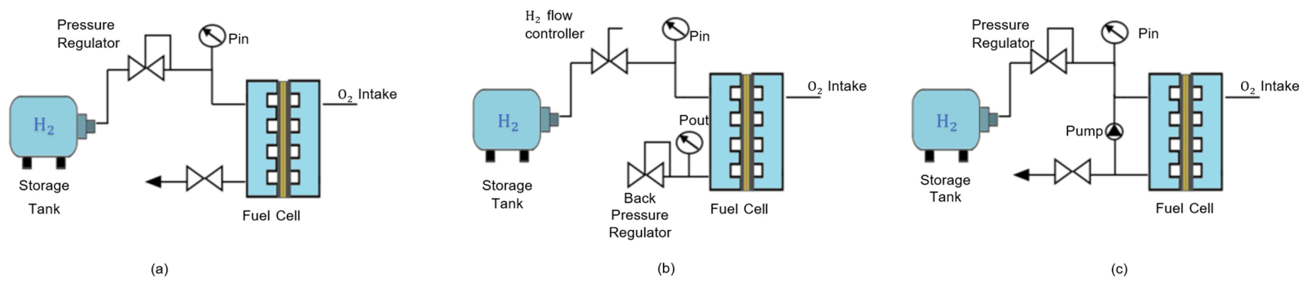
Figure 4. Hydrogen feeding modes. (a) Dead-end mode; (b) flow-through mode; (c) recirculation mode.
The next section is oriented to the modelling of FC systems, with a specific focus on PEMFCs. This attention to PEMFCs is due to their alignment with various parameters and reasons to address diverse challenges, including high energy efficiency, low operational temperatures, rapid start-up capabilities, and adaptability for a wide array of applications.
References
- Lagioia, G.; Spinelli, M.P.; Amicarelli, V. Blue and green hydrogen energy to meet European Union decarbonisation objectives. An overview of perspectives and the current state of affairs. Int. J. Hydrogen Energy 2023, 48, 1304–1322.
- Sun, C.; Negro, E.; Vezzù, K.; Pagot, G.; Cavinato, G.; Nale, A.; Herve Bang, Y.; Di Noto, V. Hybrid inorganic-organic proton-conducting membranes based on SPEEK doped with WO3 nanoparticles for application in vanadium redox flow batteries. Electrochim. Acta 2019, 309, 311–325.
- Dutta, S. A review on production, storage of hydrogen and its utilization as an energy resource. J. Ind. Eng. Chem. 2014, 20, 1148–1156.
- Spiegel, C.; York, N.; San, C.; Lisbon, F.; Madrid, L.; City, M.; New, M.; San, D.; Singapore, J.S.; Toronto, S. Designing and Building Fuel Cells; McGraw-Hill: New York, NY, USA, 2007; ISBN 0-07-148977-0.
- Al-Baghdadi, M.A.R.S. Proton exchange membrane fuel cells modeling: A review of the last ten years results of the Fuel Cell Research Center-IEEF. Int. J. Energy Environ. 2017, 8, 1–28.
- Lin, R.H.; Xi, X.N.; Wang, P.N.; Wu, B.D.; Tian, S.M. Review on hydrogen fuel cell condition monitoring and prediction methods. Int. J. Hydrogen Energy 2019, 44, 5488–5498.
- Onanena, R.; Oukhellou, L.; Candusso, D.; Same, A.; Hissel, D.; Aknin, P. Estimation of fuel cell operating time for predictive maintenance strategies. Int. J. Hydrogen Energy 2010, 35, 8022–8029.
- Knowles, M.; Ren, Q.; Baglee, D. The state of the art in Fuel Cell condition monitoring and maintenance. World Electr. Veh. J. 2010, 4, 487–494.
- Borup, R.; Meyers, J.; Pivovar, B.; Kim, Y.S.; Mukundan, R.; Garland, N.; Myers, D.; Wilson, M.; Garzon, F.; Wood, D.; et al. Scientific aspects of polymer electrolyte fuel cell durability and degradation. Chem. Rev. 2007, 107, 3904–3951.
- Pan, T.; Zhang, P.; Du, C.; Wu, D. A review of fault diagnosis and fault-tolerant control of vehicular polymer electrolyte membrane fuel cell power system. J. Phys. Conf. Ser. 2022, 2206, 012015.
- Brik, K.; Ben Ammar, F.; Djerdir, A.; Miraoui, A. Causal and fault trees analysis of proton exchange membrane fuel cell degradation. J. Fuel Cell Sci. Technol. 2015, 12, 051002.
- Chen, J.; Zhou, B. Diagnosis of PEM fuel cell stack dynamic behaviors. J. Power Sources 2008, 177, 83–95.
- Miller, M.; Bazylak, A. A review of polymer electrolyte membrane fuel cell stack testing. J. Power Sources 2011, 196, 601–613.
- Aitouche, A.; Olteanu, S.C.; Ould Bouamama, B. A Survey of Diagnostic of Fuel Cell Stack Systems; IFAC: Prague, Czech Republic, 2012; Volume 45, ISBN 9783902823090.
- Zheng, Z.; Petrone, R.; Péra, M.C.; Hissel, D.; Becherif, M.; Pianese, C.; Yousfi Steiner, N.; Sorrentino, M. A review on non-model based diagnosis methodologies for PEM fuel cell stacks and systems. Int. J. Hydrogen Energy 2013, 38, 8914–8926.
- Silveira, J.L.; Martins Leal, E.; Ragonha, L.F. Analysis of a molten carbonate fuel cell: Cogeneration to produce electricity and cold water. Energy 2001, 26, 891–904.
- Pu, Z.; Zhang, G.; Hassanpour, A.; Zheng, D.; Wang, S.; Liao, S.; Chen, Z.; Sun, S. Regenerative fuel cells: Recent progress, challenges, perspectives and their applications for space energy system. Appl. Energy 2021, 283, 116376.
- Sammes, N.; Bove, R.; Stahl, K. Phosphoric acid fuel cells: Fundamentals and applications. Curr. Opin. Solid State Mater. Sci. 2004, 8, 372–378.
- Kamarudin, S.K.; Achmad, F.; Daud, W.R.W. Overview on the application of direct methanol fuel cell (DMFC) for portable electronic devices. Int. J. Hydrogen Energy 2009, 34, 6902–6916.
- Das, S.; Das, D.; Patra, A. Operation of Solid Oxide Fuel Cell based Distributed Generation. Energy Procedia 2014, 54, 439–447.
- Andrade, P.; Bento, F.; Alcaso, A.N.; Marques Cardoso, A.J. Output Current Control for Two-Switch Boost Buck Converters in Fuel Cell Applications for DC Microgrids. In Proceedings of the 2023 International Conference on Clean Electrical Power (ICCEP), Terrasini, Italy, 27–29 June 2023; pp. 136–140.
- Jiang, S.P.; Li, Q. Phosphoric Acid Fuel Cells. In Introduction to Fuel Cells; Springer: Singapore, 2021; pp. 649–671. ISBN 0387355375.
- Sun, Q.; Lin, D.; Khayatnezhad, M.; Taghavi, M. Investigation of phosphoric acid fuel cell, linear Fresnel solar reflector and Organic Rankine Cycle polygeneration energy system in different climatic conditions. Process Saf. Environ. Prot. 2021, 147, 993–1008.
- Szablowski, L.; Dybinski, O.; Szczesniak, A.; Milewski, J. Mathematical Model of Steam Reforming in the Anode Channel of a Molten Carbonate Fuel Cell. Energies 2022, 15, 608.
- Contreras, R.R.; Almarza, J.; Rincón, L. Molten carbonate fuel cells: A technological perspective and review. Energy Sources Part A Recover. Util. Environ. Eff. 2021, 7, 1273–1283.
- Izurieta, E.M.; Cañete, B.; Pedernera, M.N.; López, E. Biofuels-based hybrid MCFC/gas turbine plant design and simulation for power and heat generation. Braz. J. Chem. Eng. 2022, 39, 759–771.
- Archit Rai, S.P. Prabhansu Renewable energy for sustainable growth assessment. In Renewable Energy for Sustainable Growth Assessment; Nayan Kumar, P., Ed.; John Wiley & Sons: New York, NY, USA, 2022; pp. 1–656. ISBN 9781119785460.
- Jang, I.; Ahn, M.; Lee, S.; Yoo, S.J. Surfactant assisted geometric barriers on PtNi@C electrocatalyst for phosphoric acid fuel cells. J. Ind. Eng. Chem. 2022, 110, 198–205.
- Nohara, T.; Arita, T.; Tabata, K.; Saito, T.; Shimada, R.; Nakazaki, H.; Suzuki, Y.; Sato, R.; Masuhara, A. Novel Filler-Filled-Type Polymer Electrolyte Membrane for PEFC Employing Poly(vinylphosphonic acid)-b-polystyrene-Coated Cellulose Nanocrystals as a Filler. ACS Appl. Mater. Interfaces 2022, 14, 8353–8360.
- Hamnett, A. Mechanism and electrocatalysis in the direct methanol fuel cell. Catal. Today 1997, 38, 445–457.
- Rao, A.S.; Rashmi, K.R.; Manjunatha, D.V.; Jayarama, A.; Veena Devi Shastrimath, V.; Pinto, R. Methanol crossover reduction and power enhancement of methanol fuel cells with polyvinyl alcohol coated Nafion membranes. Mater. Today Proc. 2019, 35, 344–351.
- Winter, M.; Brodd, R.J. What are batteries, fuel cells, and supercapacitors? Chem. Rev. 2004, 104, 4245–4269.
- Kurnia, J.C.; Chaedir, B.A.; Sasmito, A.P.; Shamim, T. Progress on open cathode proton exchange membrane fuel cell: Performance, designs, challenges and future directions. Appl. Energy 2021, 283, 116359.
- Yan, S.; Yang, M.; Sun, C.; Xu, S. Liquid Water Characteristics in the Compressed Gradient Porosity Gas Diffusion Layer of Proton Exchange Membrane Fuel Cells Using the Lattice Boltzmann Method. Energies 2023, 16, 6010.
- Barbir, F. PEM Fuel Cells: Theory and Practice, 1st ed.; Dorf, R.C., Ed.; Elsevier Academic Press: San Diego, CA, USA, 2005.
More
Information
Subjects:
Engineering, Electrical & Electronic
Contributors
MDPI registered users' name will be linked to their SciProfiles pages. To register with us, please refer to https://encyclopedia.pub/register
:
View Times:
557
Revisions:
2 times
(View History)
Update Date:
09 Feb 2024
Table of Contents


Notice
You are not a member of the advisory board for this topic. If you want to update advisory board member profile, please contact office@encyclopedia.pub.
OK
Confirm
Only members of the Encyclopedia advisory board for this topic are allowed to note entries. Would you like to become an advisory board member of the Encyclopedia?
Yes
No
${ textCharacter }/${ maxCharacter }
Submit
Cancel
Back
Comments
${ item }
|
${ item.createdUser.fullName }
${ item.createdAt }
${ item.vote }
${ item.reply }
Delete
${ reply.createdUser.fullName }
${ reply.createdAt }
${ reply.vote }
Delete
There is no reply to this comment~
${ item.replyTextCharacter }/${ item.replyMaxCharacter }
Submit
Cancel
More
No more~
There is no comment~
${ textCharacter }/${ maxCharacter }
Submit
Cancel
${ selectedItem.replyTextCharacter }/${ selectedItem.replyMaxCharacter }
Submit
Cancel
Confirm
Are you sure to Delete?
Yes
No