Conventional driven piles are made from steel, concrete, timber, or composite materials. These piling options have limitations with respect to corrosion, durability, driveablity, and performance. Ultra-High-Performance Concrete (UHPC) pile is a new alternative that has already been adopted by various state Departments of Transportation in the United States for addressing the limitations that exist with conventional piles. UHPC piles are made of a cementitious composite material mixture that possesses exceptional properties such as higher strength, low capillary porosity, and high resistance to corrosion, making them a suitable option for use as a deep foundation. For several reasons, it is necessary to cast piles with a shorter length and splice them at the site to reach the desired lengths.
1. UHPC Piles
The Federal Highway Administration (FHWA)
[1] defines Ultra-High-Performance Concrete (UHPC) as a “cementitious composite material composed of an optimized gradation of granular constituents, a water-to-cementitious materials ratio less than 0.25, and a high percentage of discontinuous internal fiber reinforcement.” UHPC is typically distinguished from other types of concrete based on its mechanical performance. Accordingly, many other definitions of UHPC also include a minimum tensile strength and/or ductility requirement, and many also specify minimum durability criteria
[2][3][4][5][6][7].
1.1. Previous Research on UHPC Piles
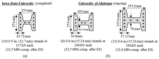
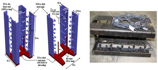
UHPC pile research to date has mostly aimed at developing UHPC pile details to replace steel H-piles. A summary of the UHPC pile cross-sections that have been or are currently being investigated is shown in
Figure 1 [8][9] and
Figure 2. There is ongoing research by the Alabama Department of Transportation (ALDOT) and the Prestressed/Precast Concrete Institute (PCI) investigating prestressed UHPC H-piles; these works are investigating 12-inch (305 mm), 14-inch (355.6 mm), and 16-inch (406 mm) UHPC H-piles with high precompression.
Figure 1b
[9] shows the details of two of the UHPC H-pile sections.
Figure 1a
[8] shows a section of a completed research work conducted at Iowa State University.
Figure 1. Summary of UHPC pile cross-sections investigated to date from (
a) Iowa State University
[8][10][11] and (
b) the University of Alabama (unpublished work)
[9].
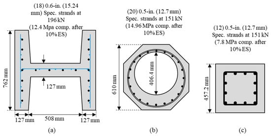
Figure 2. Details of UHPC piles by FDOT: (a) 30-inch (762 mm) H-pile; (b) 24-inch (610 mm) octagonal pile; and (c) 18-inch (457.2 mm) square pile (unpublished work).
The Florida Department of Transportation (FDOT) is currently investigating several UHPC piles with different shapes. The configuration and shape of some of the UHPC pile sections are shown in Figure 2.
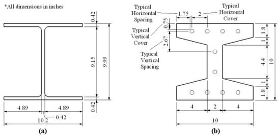
Voort et al.
[8] developed a tapered H-shaped UHPC pile section aimed at replacing an HP 10 × 57-inch (254 × 1448 mm) steel pile, as shown in
Figure 3 [8]. The outside dimensions of the piles are almost identical, which allowed them to be driven using similar equipment.
Figure 3. Dimensions of (
a) HP 10 × 57 steel pile and (
b) UHPC tapered H-shaped pile
[8].
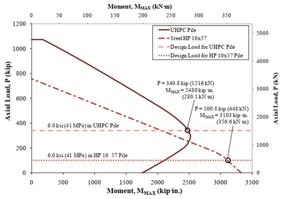
The moment–axial load interaction diagrams for these UHPC H-piles and HP 10 × 57-inch (254 × 1448 mm) steel piles are shown in
Figure 4 [8]. The axial load applied to generate 6 ksi (41 MPa) compressive stress in the piles is highlighted, as this was the axial stress limit used in the design in Iowa where the research was conducted. Voort et al.
[8] highlighted that although the moment capacity of the UHPC pile was less, the axial load at 6 ksi (41 MPa) axial stress is over three times greater for the UHPC pile compared to steel H-pile. They mentioned that the axial capacity is more significant since it typically controls the design.
Figure 4. Moment–axial load interaction diagram for UHPC and HP 10 × 57 pile sections with equivalent axial load
[8].
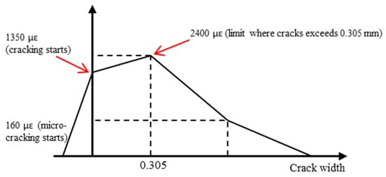
Garder et al.
[10] also investigated the cracking performance of UHPC piles, as the piles would lose their long-term durability performance if cracking was to occur. They assumed a strain versus crack width relationship, as shown in
Figure 5 [8][10]. Based on the results from Voort et al.
[8] for the strains when micro-cracking started, cracking started when cracks exceeded 0.012 in. (0.305 mm).
Figure 5. Simplified tensile strength law with tensile strain assumptions, based on
[8][10].
They also compared the moment curvature analysis results for both UHPC and HP 10 × 57-inch (254 × 1448 mm) piles at strong and weak axis bending for four different axial load cases. They suggested that the service moment should be considered for UHPC pile design to ensure that cracking does not occur in UHPC piles in service
[10].
1.2. UHPC Pile Application in Foundation Construction
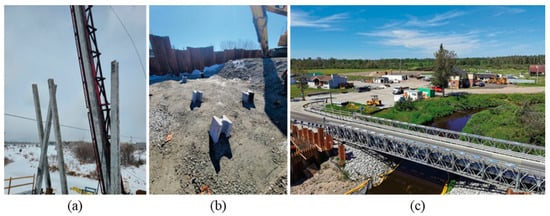
UHPC piles have already been used in several construction projects. They were used for one abutment for Lily River Detour Bridge (Highway 11) in Ontario, Canada, in 2020
[12]. One abutment utilized UHPC H-piles, and the other abutment implemented steel H-piles with the same outside dimensions. Photographs of the bridge during construction are shown in
Figure 6 [12].
Figure 6. UHPC piles used in Ontario, Canada, (
a) driven of UHPC piles, (
b) driven piles at cut-off elevation, and (
c) completed bridge
[12].
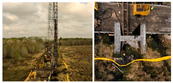
The Florida Department of Transportation (FDOT)
[13] included a 30-inch (762 mm) UHPC H-pile in the CR 339 over Waccasassa River Bridge. The 30-inch (762 mm) UHPC H-pile was used as a substitute for a 20-inch (508 mm) square prestressed concrete pile that was used for the rest of the piles in the structure. Photographs of the driving process are shown in
Figure 7 [13].
Figure 7. UHPC H-pile driven for the CR 339 over Waccasassa River Bridge
[13].
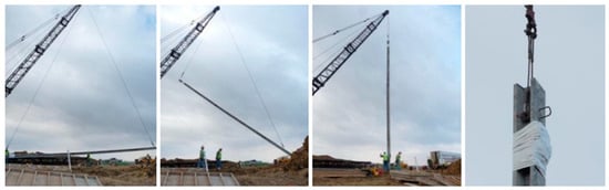
Garder et al.
[10] reported the field implementation of a single UHPC H-pile on a bridge project in Sac County, Iowa, near the intersection of US 20 over US 71. The bridge has three spans, a total length of 6.1 m, 12.2 m width, and 24-degree skew. The lifting and installation process is illustrated in
Figure 8 [10].
Figure 8. Lifting and installation of UHPC H-pile in Iowa test project
[10].
2. UHPC Pile Splices
During construction, for various reasons, it may be beneficial or necessary to cast piles with shorter lengths and splice them at the site to form a longer pile length. In preplanned situations, piles may be equipped in advance with connection parts and devices to facilitate splicing at the site. In unplanned situations, piles may be joined with more efforts at the site involving drilling and other modifications. Pile splice must be capable of resisting stresses induced by driving and service loads. Splices should be effective without a significant increase in the project time, be durable, and cost effective
[10].
In the next section, the available splicing methods that can be applied to UHPC piles are reviewed. Accordingly, it first discusses the splicing technique that is solely developed for UHPC piles. Then, it explores some of the splicing methods that have been developed for conventional PPCPs in general but can also be implemented for UHPC piles. Lastly, some new splicing systems
[14][15][16][17] using advanced materials such as fiber-reinforced polymer (FRP) sheet or jacket, Near-Surface-Mounted (NSM) FRP, and the use of mechanical couplers are introduced.
2.1. Previous Work on UHPC Pile Splice
Garder et al.
[10] developed a splice detail for UHPC piles involving a steel embedment in the ends of each pile, shown in
Figure 9 [10], with field welding of the embedment on both sides to create the splice. The splice was designed to develop the full moment and shear capacity of the UHPC pile section. They adopted the welded pile splice option, which is typically common to steel H-pile splice, so there were no concerns with field welding being a new practice for splicing UHPC piles.
Figure 9. UHPC pile splice embedment developed by Garder et al.
[10].
Garder et al.
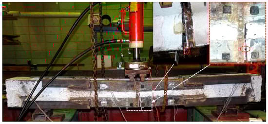
[10] tested the developed splice detail in direct tension, flexure, and shear. The specimen failed in the initial direct tension test at a load of 103 kips (458 kN), 27.4% of the unspliced pile tension capacity, toward one of the supports (outside of the splice region).
The failure of the test specimens occurred due to the fracture of the weld between the corner angle and the 0.5-inch (12.7 mm) end plate of the pile splice, shown in
Figure 10 [10]. It was concluded that the shop welding at the precast plant had a shorter length between the corner angle and end plate than specified, which led to the failure of the splice. They recommend a full penetration weld between the edge angles and end plate.
Figure 10. Photograph of failure of the UHPC pile splice from Garder et al.
[10] for bending about the weak axis.
At the time of writing, this is the sole published work on the welded splice method for UHPC pile.
2.2. Other PPCP Splices Applicable to UHPC Piles
Splice systems that have been used for conventional PPCPs and can be further implemented for UHPC piles are discussed in this section.
2.2.1. Bolted Splices
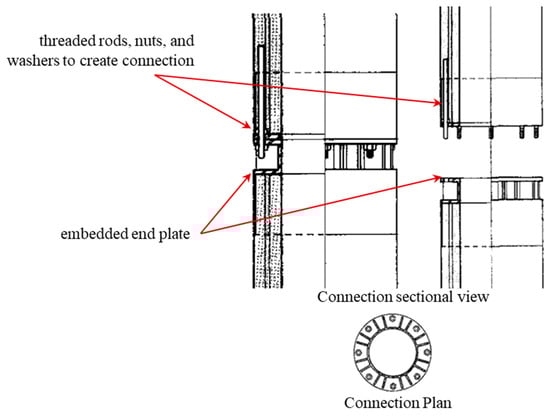
The Japanese bolted splice discussed by Bruce and Hebert
[18] includes an embedded end plate with threaded rods extending into the splice region and creating the field splice, as shown in
Figure 11 [18]. The end plates have recesses in the concrete that provide spaces for tightening the bolt hex nuts and threaded rods.
Figure 11. Japanese bolted pile splice connection discussed by Bruce and Hebert
[18].
Another type of bolted connection is the NU chuck splice system, shown in
Figure 12 [19][20]. This system also has strands anchored to the end plates, with the splicing of piles occurring through large threaded rods and four hex nuts. Experimental research showed that the splices could reach sufficient capacity, but a brittle failure mechanism and strand slippage at the end plates were observed
[19][20].
Figure 12. NU chuck splice system
[19][20].
This splicing method can satisfy the required capacity, and the main disadvantage is that the recess area in the concrete restricts the configuration of the strands.
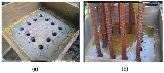
2.2.2. Epoxy-Bonded Dowel Splices
Epoxy-bonded dowel splices are created by casting or drilling holes in the top of the lower pile to receive dowel rebars protruding out of the lower end of the upper pile. Dowel bars can be made of carbon steel, stainless steel (SS), carbon fiber-reinforced polymer (CFRP), or glass fiber-reinforced polymer (GFRP). The dowel rebars must have adequate length to bond with the other pile segment. Different types of resin and cementitious grouts can be used as filler and bonding agents to connect the pile segments
[21][22].
Corrosion-resistant dowel bars are often chosen as they can increase the durability of pile splices
[23]. One drawback of this splice type is that the epoxy must be cured before driving of the spliced pile can resume to ensure that the pile splice has sufficient tensile strength. This can be overcome by placing a cushion between the pile segments and continuing to drive while the epoxy is still wet
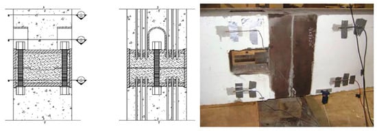
[24]. Also, the in-place flexural strength of the pile splices is limited for this option, especially in an unplanned situation. An example of an epoxy dowel pile splice is shown in
Figure 13 [22].
Figure 13. Epoxy-bonded dowel splices: (
a) drilled holes at the pile segment; (
b) rebar dowels with epoxy
[22].
This method is commonly used for splicing in the field and requires low material and labor. Epoxy-bonded dowel splices are the most common splicing technique used in the state of Florida
[24].
2.2.3. Post-Tensioned Splices
Post-tensioning ducts can be used to form a connection between two pile segments. Splice is achieved by running post-tensioning strands through this duct across the two-pile segment. The strands are then tensioned and stressed to form connections. Post-tensioned splices can increase the tensile capacity near the ends of the prestressed pile and the splice region
[21] and provide good bending and tensile strengths
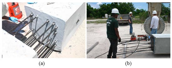
[19]. Mullins and Sen
[24] developed a post-tensioned splice detail where embedded anchors are provided in the ends of the piles (dually embedded anchors), as shown in
Figure 14 [24].
Figure 14. Details for dually embedded anchorage concept
[24].
For this detail, strands were inserted into the anchors on each side, see
Figure 15a
[24], and then post-tensioned from the end of the top pile, see
Figure 15b
[24]. The post-tensioned strands were grouted after tensioning.
Figure 15. Photographs from splice construction by Mullins and Sen
[24], (
a) strand insertion at splice and (
b) post-tensioning of spliced strands.
Some drawbacks associated with this splice option usage are that it is susceptible to corrosion, and this limits its implementation in marine environments, the cost of materials and the technicality involved makes it an expensive option, and it will be difficult to use in unplanned situations
[19][24][25].
2.2.4. Fiber-Reinforced Polymer (FRP) Sheet/Jacket
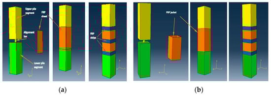
The FRP sheet/jacket concept has been introduced by Khedmatgozar Dolati and Mehrabi
[14][17] as an innovative alternative to the existing methods for connecting driven pile segments both in preplanned and unplanned situations. The splicing system consists of an alignment bar and FRP sheet (layers of carbon fiber-reinforced polymer or glass fiber polymer), which are bonded to the pile segment with resin/epoxy, as presented in
Figure 16a
[14].
Figure 16. Schematic illustration: (
a) FRP sheet; (
b) FRP jacket
[14].
The FRP material can also be made in a jacket form with four sides already connected like a box. In a preplanned situation, the jacket can be pre-fitted and pre-attached to the upper pile segment at the precast plant, as illustrated in
Figure 16b
[14]. To account for the shear resistance, confinement, and premature pealing of FRP, bi-directional FRP strips can be used as shown in this figure. In preplanned situations, concrete can be recessed in the splicing area to avoid a larger cross-section for splice in the case of soils with frictional resistance. The system has excellent corrosion resistance.
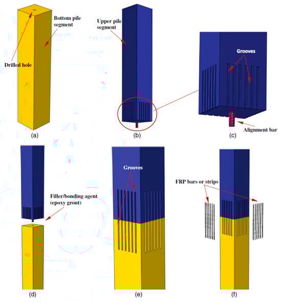
2.2.5. Near-Surface-Mounted Fiber-Reinforced Polymer (NSM FRP)
For this method, external grooves are cut and installed with FRP (or other material) bars and bonded to the concrete pile with epoxy adhesives to create connections, as shown in
Figure 17 [15]. The grooves can be cut in or formed during casting. An alignment bar is used between the two pile segments
[15][16][26]. The alignment holes and segment interfaces are sealed with epoxy or other bonding agents. NSM FRP splice offers an economical, labor friendly, durable option for pile-splicing and can be used in both unplanned and planned pile-splicing situations.
Figure 17. Schematic illustration of NSM FRP pile-splicing method: (
a) bottom pile segment; (
b) upper pile segment; (
c) close-up of grooves and alignment bar; (
d) lowering upper pile segment; (
e) extending grooves into the lower segment; and (
f) installing FRP bars or strips inside grooves
[15]. “Reprinted with permission from
[15] 2024, American Society of Civil Engineer (ASCE)”.
2.2.6. Mechanical Coupler
In this connection system, sleeves (coupler) are inserted into the lower pile segment and are connected to the upper segment by splicing steel reinforcement. The space between the bars and sleeve is filled with grouts. There are different types of couplers available on the market, which include shear screw couplers, headed bar couplers, grouted sleeve couplers, threaded couplers, and swaged couplers
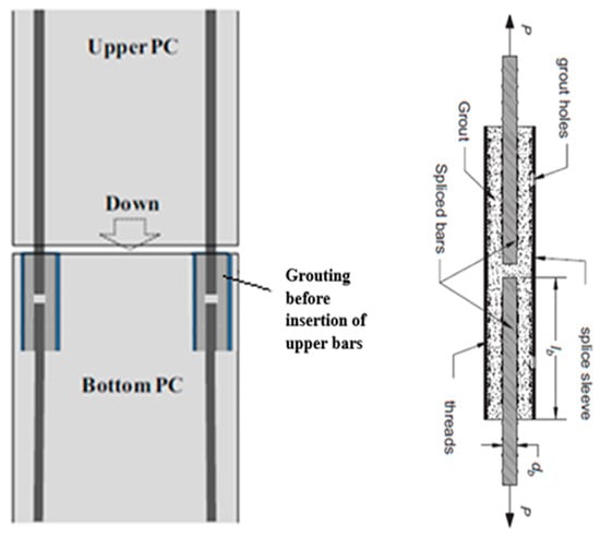
[19][27][28][29]. The most common type of mechanical couplers are grouted splice couplers, as shown in
Figure 18 [30].
Figure 18. Mechanical coupler pile-splicing method
[30].
Handling and installation are easier with this method, and it is an economical alternate method to other available options. Due to the advance preparation needed in the lower segment of the pile, this connection system is suitable only for preplanned situations, and it can fully develop the required strength needed for this situation.
 +1 credit