 +1 credit
| Version | Summary | Created by | Modification | Content Size | Created at | Operation |
|---|---|---|---|---|---|---|
| 1 | Neelesh Bhadwal | -- | 4556 | 2024-01-10 09:09:18 |
Video Upload Options
The highest energy conversion efficiencies are typically shown by lead-containing piezoelectric materials, but the harmful environmental impacts of lead and its toxicity limit future use. At the bulk scale, lead-based piezoelectric materials have significantly higher piezoelectric properties when compared to lead-free piezoelectric materials. However, at the nanoscale, the piezoelectric properties of lead-free piezoelectric material can be significantly larger than the bulk scale.
1. Introduction
| Material | Values | Crystallinity | % β-Phase | d33 (pC/N) |
εr | d332/(εrε0) or d33g33 (m2/N × 10−12) |
Reference |
|---|---|---|---|---|---|---|---|
| PVDF (Bulk) |
Generally Accepted Values |
~50–60% [13] | - | −13–(−35) | 8–15 | 17 | [23][33][34][35][36] |
| Different Industrial Datasheets |
- | - | −30 | 8–10 | 12 | [37] | |
| - | >80% of total crystallinity |
−23–(−28) | 13.5 | 6.6 | [38] | ||
| - | - | −33 | - | - | [39] | ||
| PVDF-TrFE (Bulk) |
Generally Accepted Values |
- | - | −24–(−39) | 5–20 | 34 | [23][33][35][36][40] |
| Different Industrial Datasheets |
80–90% [41] | - | >25 | 7.5–8.5 | 9.5 | [42] | |
| - | - | −38 | 7.9 | 21 | [43] |
Bulk PVDF and PVDF-TrFE both have negative d33 coefficients, as opposed to most traditional piezoelectric ceramics, which have positive d33 coefficients [44][45][46][47]. Physically, this means that when an electric field is exerted in the direction of polarization of a traditional piezoelectric ceramic, it will expand, while PVDF and PVDF-TrFE contract [44].
To enable the use of piezoelectric energy harvesters in more practical applications, their power density must be increased as current harvesters can only power ultra-low-power-consuming devices. These harvesters should use materials with high piezoelectric properties in composite designs that improve the overall power output. The appropriateness of PVDF and PVDF-TrFE lead-free piezoelectric nanomaterials as the main piezoelectric material in piezoelectric energy harvesters is examined. The appropriateness is based on the nanomaterial’s piezoelectric properties and the power output of different PVDF/PVDF-TrFE composite structures.
2. Power Density-Improving Techniques
3. Piezoelectric Nanogenerator Composite Structure and Power Output
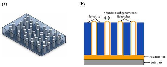
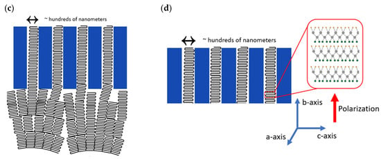
3.1. (1-3 Composites) Vertically Aligned PVDF/PVDF-TrFE Nanowires and Nanotubes
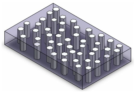
3.2. (3-1 Composites) Piezoelectric Vertically Aligned Nanorods Encapsulated in PVDF
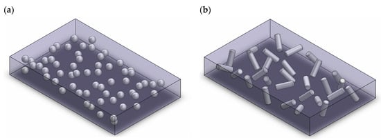
3.3. (3-0 Composites) PVDF/PVDF-TrFE Composites with Non-Vertically Aligned Nanoparticles
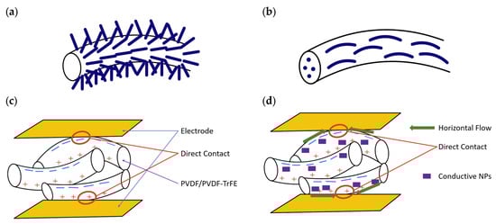
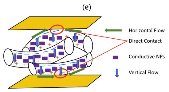
3.4. Electrospun Fibers
References
- Liu, W.-D.; Yin, L.-C.; Li, L.; Yang, Q.; Wang, D.-Z.; Li, M.; Shi, X.-L.; Liu, Q.; Bai, Y.; Gentle, I. Grain boundary re-crystallization and sub-nano regions leading to high plateau figure of merit for Bi2Te3 nanoflakes. Energy Environ. Sci. 2023, 16, 5123–5135.
- Zhang, R.; Olin, H. Material choices for triboelectric nanogenerators: A critical review. EcoMat 2020, 2, e12062.
- Hu, D.; Yao, M.; Fan, Y.; Ma, C.; Fan, M.; Liu, M. Strategies to achieve high performance piezoelectric nanogenerators. Nano Energy 2019, 55, 288–304.
- Bhadwal, N.; Ben Mrad, R.; Behdinan, K. Review of Zinc Oxide Piezoelectric Nanogenerators: Piezoelectric Properties, Composite Structures and Power Output. Sensors 2023, 23, 3859.
- Briscoe, J.; Dunn, S. Piezoelectric nanogenerators–a review of nanostructured piezoelectric energy harvesters. Nano Energy 2015, 14, 15–29.
- Xu, S.; Wei, Y.; Liu, J.; Yang, R.; Wang, Z.L. Integrated multilayer nanogenerator fabricated using paired nanotip-to-nanowire brushes. Nano Lett. 2008, 8, 4027–4032.
- Fujii, I.; Nakashima, K.; Kumada, N.; Wada, S. Structural, dielectric, and piezoelectric properties of BaTiO3–Bi (Ni1/2Ti1/2) O3 ceramics. J. Ceram. Soc. Jpn. 2012, 120, 30–34.
- Lu, L.; Ding, W.; Liu, J.; Yang, B. Flexible PVDF based piezoelectric nanogenerators. Nano Energy 2020, 78, 105251.
- Le, A.T.; Ahmadipour, M.; Pung, S.-Y. A review on ZnO-based piezoelectric nanogenerators: Synthesis, characterization techniques, performance enhancement and applications. J. Alloys Compd. 2020, 844, 156172.
- Goel, S.; Kumar, B. A review on piezo-/ferro-electric properties of morphologically diverse ZnO nanostructures. J. Alloys Compd. 2020, 816, 152491.
- Wang, Z.L. Zinc oxide nanostructures: Growth, properties and applications. J. Phys. Condens. Matter 2004, 16, R829.
- Liu, Y.; Wang, L.; Zhao, L.; Yu, X.; Zi, Y. Recent progress on flexible nanogenerators toward self-powered systems. InfoMat 2020, 2, 318–340.
- Lovinger, A.J. Ferroelectric polymers. Science 1983, 220, 1115–1121.
- Ohigashi, H.; Itoh, T.; Kimura, K.; Nakanishi, T.; Suzuki, M. Analysis of frequency response characteristics of polymer ultrasonic transducers. Jpn. J. Appl. Phys. 1988, 27, 354.
- Murayama, N.; Nakamura, K.; Obara, H.; Segawa, M. The strong piezoelectricity in polyvinylidene fluroide (PVDF). Ultrasonics 1976, 14, 15–24.
- Kawai, H. The piezoelectricity of poly (vinylidene fluoride). Jpn. J. Appl. Phys. 1969, 8, 975.
- Marutake, M. The days when piezoelectric PVDF was discovered. Ferroelectrics 1995, 171, 5–6.
- Arkema. Performance Characteristics & Data of Kynar® PVDF; Arkema: Colombes, France, 2023.
- Arkema. KYNAR (PVDF) Chemical Compatibility & Chemical Resistance Chart; Arkema: Colombes, France, 2015.
- Arkema. High Performance Polymers Medical Grades and Technical Data Sheets; Arkema: Colombes, France, 2022.
- Lovinger, A.J. Annealing of poly (vinylidene fluoride) and formation of a fifth phase. Macromolecules 1982, 15, 40–44.
- Bera, B.; Sarkar, M.D. Piezoelectricity in PVDF and PVDF based piezoelectric nanogenerator: A concept. IOSR J. Appl. Phys 2017, 9, 95–99.
- Shepelin, N.A.; Glushenkov, A.M.; Lussini, V.C.; Fox, P.J.; Dicinoski, G.W.; Shapter, J.G.; Ellis, A.V. New developments in composites, copolymer technologies and processing techniques for flexible fluoropolymer piezoelectric generators for efficient energy harvesting. Energy Environ. Sci. 2019, 12, 1143–1176.
- Alam, M.M.; Crispin, X. The past, present, and future of piezoelectric fluoropolymers: Towards efficient and robust wearable nanogenerators. Nano Res. Energy 2023, 2, e9120076.
- PyzoFlex. Properties of PVDF and Its copolymers. Available online: https://www.pyzoflex.com/fileadmin/ProduktWebseiten/pyzoflex/06-PVDF-and-its-Copolymers.pdf (accessed on 11 September 2023).
- Furukawa, T.; Date, M.; Fukada, E.; Tajitsu, Y.; Chiba, A. Ferroelectric behavior in the copolymer of vinylidenefluoride and trifluoroethylene. Jpn. J. Appl. Phys. 1980, 19, L109.
- Yagi, T.; Tatemoto, M.; Sako, J.-I. Transition behavior and dielectric properties in trifluoroethylene and vinylidene fluoride copolymers. Polym. J. 1980, 12, 209–223.
- Furukawa, T. Ferroelectric properties of vinylidene fluoride copolymers. Phase Transit. A Multinatl. J. 1989, 18, 143–211.
- Fujisaki, Y. Poly (vinylidenefluoride-trifluoroethylene) P (VDF-TrFE)/semiconductor structure ferroelectric-gate FETs. In Ferroelectric-Gate Field Effect Transistor Memories: Device Physics and Applications; Springer: Berlin/Heidelberg, Germany, 2016; pp. 157–183.
- Jaffe, B.; Cook, W.; Jaffe, H. Ceramics Piezoelectric; Elsevier: Amsterdam, The Netherlands, 1971.
- APC International Ltd. Piezoelectric Constants. Available online: https://www.americanpiezo.com/knowledge-center/piezo-theory/piezoelectric-constants.html (accessed on 20 September 2023).
- Kulkarni, V.; Ben-Mrad, R.; Prasad, S.E.; Nemana, S. A shear-mode energy harvesting device based on torsional stresses. IEEE/ASME Trans. Mechatron. 2013, 19, 801–807.
- Ramadan, K.S.; Sameoto, D.; Evoy, S. A review of piezoelectric polymers as functional materials for electromechanical transducers. Smart Mater. Struct. 2014, 23, 033001.
- Döring, J.; Bovtun, V.; Bartusch, J.; Beck, U.; Kreutzbruck, M. Cellular polypropylene ferroelectret film: Piezoelectric material for non-contact ultrasonic transducers. In Proceedings of the 17th World Conference on Nondestructive Testing, Shanghai, China, 25–28 October 2008; pp. 25–28.
- Crossley, S.; Whiter, R.; Kar-Narayan, S. Polymer-based nanopiezoelectric generators for energy harvesting applications. Mater. Sci. Technol. 2014, 30, 1613–1624.
- Xie, L.; Wang, G.; Jiang, C.; Yu, F.; Zhao, X. Properties and applications of flexible poly (vinylidene fluoride)-based piezoelectric materials. Crystals 2021, 11, 644.
- Acoustics, P. PVdF Film -Its Properties and Uses. Available online: https://www.acoustics.co.uk/wp-content/uploads/2022/04/Uses-and-properties-of-poled-PVDF-V1-0422.pdf (accessed on 11 September 2023).
- PolyK. PolyK Piezo PVDF Properties. Available online: https://piezopvdf.com/piezo-pvdf-film-kit/ (accessed on 22 August 2023).
- Connectivity, T. Metallized Piezo Film Sheets. Available online: https://www.te.com/commerce/DocumentDelivery/DDEController?Action=showdoc&DocId=Data+Sheet%7FMetallized_Piezo_Film_Sheets%7FA1%7Fpdf%7FEnglish%7FENG_DS_Metallized_Piezo_Film_Sheets_A1.pdf%7FCAT-PFS0003 (accessed on 22 August 2023).
- Xu, H. Dielectric properties and ferroelectric behavior of poly (vinylidene fluoride-trifluoroethylene) 50/50 copolymer ultrathin films. J. Appl. Polym. Sci. 2001, 80, 2259–2266.
- PolyK. PVDF-TrFE Copolymer. Available online: https://www.polyk-lab.com/PVDF-TrFE-Summary.pdf (accessed on 11 September 2023).
- PolyK. PVDF-TrFE Copolymer 75/25 Poled Piezoelectric Film, High d33. Available online: https://piezopvdf.com/pvdf-trfe-c25-piezo-film-100mm/ (accessed on 11 September 2023).
- Measurement Specialties, Inc. Piezo Film Sensors Technical Manual; Measurement Specialties, Inc.: Norristown, PA, USA, 1999.
- You, L.; Zhang, Y.; Zhou, S.; Chaturvedi, A.; Morris, S.A.; Liu, F.; Chang, L.; Ichinose, D.; Funakubo, H.; Hu, W. Origin of giant negative piezoelectricity in a layered van der Waals ferroelectric. Sci. Adv. 2019, 5, eaav3780.
- Liu, Y.; Wang, Q. Ferroelectric polymers exhibiting negative longitudinal piezoelectric coefficient: Progress and prospects. Adv. Sci. 2020, 7, 1902468.
- Katsouras, I.; Asadi, K.; Li, M.; Van Driel, T.B.; Kjaer, K.S.; Zhao, D.; Lenz, T.; Gu, Y.; Blom, P.W.; Damjanovic, D. The negative piezoelectric effect of the ferroelectric polymer poly (vinylidene fluoride). Nat. Mater. 2016, 15, 78–84.
- Bystrov, V.S.; Paramonova, E.V.; Bdikin, I.K.; Bystrova, A.V.; Pullar, R.C.; Kholkin, A.L. Molecular modeling of the piezoelectric effect in the ferroelectric polymer poly (vinylidene fluoride)(PVDF). J. Mol. Model. 2013, 19, 3591–3602.
- Zhang, L.; Li, S.; Zhu, Z.; Rui, G.; Du, B.; Chen, D.; Huang, Y.F.; Zhu, L. Recent Progress on Structure Manipulation of Poly (vinylidene fluoride)-Based Ferroelectric Polymers for Enhanced Piezoelectricity and Applications. Adv. Funct. Mater. 2023, 33, 2301302.
- Wang, F.; Zhao, X.; Li, J. PVDF energy-harvesting devices: Film preparation, electric poling, energy-harvesting efficiency. In Proceedings of the 2015 IEEE Conference on Electrical Insulation and Dielectric Phenomena (CEIDP), Ann Arbor, MI, USA, 18–21 October 2015; pp. 80–83.
- Das Gupta, D.; Doughty, K. Changes in X-ray diffraction patterns of polyvinylidene fluoride due to corona charging. Appl. Phys. Lett. 1977, 31, 585–587.
- Soin, N.; Boyer, D.; Prashanthi, K.; Sharma, S.; Narasimulu, A.A.; Luo, J.; Shah, T.H.; Siores, E.; Thundat, T. Exclusive self-aligned β-phase PVDF films with abnormal piezoelectric coefficient prepared via phase inversion. Chem. Commun. 2015, 51, 8257–8260.
- Chen, S.; Li, X.; Yao, K.; Tay, F.E.H.; Kumar, A.; Zeng, K. Self-polarized ferroelectric PVDF homopolymer ultra-thin films derived from Langmuir–Blodgett deposition. Polymer 2012, 53, 1404–1408.
- Rodriguez, B.J.; Jesse, S.; Kalinin, S.V.; Kim, J.; Ducharme, S.; Fridkin, V. Nanoscale polarization manipulation and imaging of ferroelectric Langmuir-Blodgett polymer films. Appl. Phys. Lett. 2007, 90, 122904.
- Bystrov, V.; Bystrova, N.; Paramonova, E.; Vizdrik, G.; Sapronova, A.; Kuehn, M.; Kliem, H.; Kholkin, A. First principle calculations of molecular polarization switching in P (VDF–TrFE) ferroelectric thin Langmuir–Blodgett films. J. Phys. Condens. Matter 2007, 19, 456210.
- Satapathy, S.; Pawar, S.; Gupta, P.; Varma, K. Effect of annealing on phase transition in poly (vinylidene fluoride) films prepared using polar solvent. Bull. Mater. Sci. 2011, 34, 727–733.
- Pan, H.; Na, B.; Lv, R.; Li, C.; Zhu, J.; Yu, Z. Polar phase formation in poly (vinylidene fluoride) induced by melt annealing. J. Polym. Sci. Part B Polym. Phys. 2012, 50, 1433–1437.
- Silva, M.; Costa, C.M.; Sencadas, V.; Paleo, A.; Lanceros-Méndez, S. Degradation of the dielectric and piezoelectric response of β-poly (vinylidene fluoride) after temperature annealing. J. Polym. Res. 2011, 18, 1451–1457.
- Meng, N.; Ren, X.; Santagiuliana, G.; Ventura, L.; Zhang, H.; Wu, J.; Yan, H.; Reece, M.J.; Bilotti, E. Ultrahigh β-phase content poly (vinylidene fluoride) with relaxor-like ferroelectricity for high energy density capacitors. Nat. Commun. 2019, 10, 4535.
- Ren, X.; Meng, N.; Zhang, H.; Wu, J.; Abrahams, I.; Yan, H.; Bilotti, E.; Reece, M.J. Giant energy storage density in PVDF with internal stress engineered polar nanostructures. Nano Energy 2020, 72, 104662.
- Farrar, D.; Ren, K.; Cheng, D.; Kim, S.; Moon, W.; Wilson, W.L.; West, J.E.; Yu, S.M. Permanent polarity and piezoelectricity of electrospun α-helical poly (α-amino acid) fibers. Adv. Mater. 2011, 23, 3954–3958.
- Yee, W.A.; Kotaki, M.; Liu, Y.; Lu, X. Morphology, polymorphism behavior and molecular orientation of electrospun poly (vinylidene fluoride) fibers. Polymer 2007, 48, 512–521.
- Wang, Y.; Zheng, J.; Ren, G.; Zhang, P.; Xu, C. A flexible piezoelectric force sensor based on PVDF fabrics. Smart Mater. Struct. 2011, 20, 045009.
- Zhao, Z.; Li, J.; Yuan, X.; Li, X.; Zhang, Y.; Sheng, J. Preparation and properties of electrospun poly (vinylidene fluoride) membranes. J. Appl. Polym. Sci. 2005, 97, 466–474.
- Shafii, C. Energy Harvesting Using PVDF Piezoelectric Nanofabric. Ph.D. Thesis, University of Toronto, Toronto, ON, Canada, 2014.
- Yu, H.; Huang, T.; Lu, M.; Mao, M.; Zhang, Q.; Wang, H. Enhanced power output of an electrospun PVDF/MWCNTs-based nanogenerator by tuning its conductivity. Nanotechnology 2013, 24, 405401.
- Rana, M.M.; Khan, A.A.; Huang, G.; Mei, N.; Saritas, R.; Wen, B.; Zhang, S.; Voss, P.; Abdel-Rahman, E.; Leonenko, Z. Porosity modulated high-performance piezoelectric nanogenerator based on organic/inorganic nanomaterials for self-powered structural health monitoring. ACS Appl. Mater. Interfaces 2020, 12, 47503–47512.
- Meng, N.; Zhu, X.; Mao, R.; Reece, M.J.; Bilotti, E. Nanoscale interfacial electroactivity in PVDF/PVDF-TrFE blended films with enhanced dielectric and ferroelectric properties. J. Mater. Chem. C 2017, 5, 3296–3305.
- Chen, X.; Shao, J.; An, N.; Li, X.; Tian, H.; Xu, C.; Ding, Y. Self-powered flexible pressure sensors with vertically well-aligned piezoelectric nanowire arrays for monitoring vital signs. J. Mater. Chem. C 2015, 3, 11806–11814.
- Steinhart, M.; Göring, P.; Dernaika, H.; Prabhukaran, M.; Gösele, U.; Hempel, E.; Thurn-Albrecht, T. Coherent kinetic control over crystal orientation in macroscopic ensembles of polymer nanorods and nanotubes. Phys. Rev. Lett. 2006, 97, 027801.
- Liew, W.H.; Mirshekarloo, M.S.; Chen, S.; Yao, K.; Tay, F.E.H. Nanoconfinement induced crystal orientation and large piezoelectric coefficient in vertically aligned P (VDF-TrFE) nanotube array. Sci. Rep. 2015, 5, 09790.
- Hong, C.-C.; Huang, S.-Y.; Shieh, J.; Chen, S.-H. Enhanced piezoelectricity of nanoimprinted sub-20 nm poly (vinylidene fluoride–trifluoroethylene) copolymer nanograss. Macromolecules 2012, 45, 1580–1586.
- Chen, X.; Tian, H.; Li, X.; Shao, J.; Ding, Y.; An, N.; Zhou, Y. A high performance P (VDF-TrFE) nanogenerator with self-connected and vertically integrated fibers by patterned EHD pulling. Nanoscale 2015, 7, 11536–11544.
- Anand, A.; Bhatnagar, M. Role of vertically aligned and randomly placed zinc oxide (ZnO) nanorods in PVDF matrix: Used for energy harvesting. Mater. Today Energy 2019, 13, 293–301.
- Choi, M.; Murillo, G.; Hwang, S.; Kim, J.W.; Jung, J.H.; Chen, C.-Y.; Lee, M. Mechanical and electrical characterization of PVDF-ZnO hybrid structure for application to nanogenerator. Nano Energy 2017, 33, 462–468.
- Cavallini, D.; Fortunato, M.; De Bellis, G.; Sarto, M. PFM Characterization of Piezoelectric PVDF/ZnONanorod thin films. In Proceedings of the 2018 IEEE 18th International Conference on Nanotechnology (IEEE-NANO), Cork, Ireland, 23–26 July 2018; pp. 1–3.
- Pusty, M.; Sinha, L.; Shirage, P.M. A flexible self-poled piezoelectric nanogenerator based on a rGO–Ag/PVDF nanocomposite. New J. Chem. 2019, 43, 284–294.
- Kuilla, T.; Bhadra, S.; Yao, D.; Kim, N.H.; Bose, S.; Lee, J.H. Recent advances in graphene based polymer composites. Prog. Polym. Sci. 2010, 35, 1350–1375.
- Kim, H.; Abdala, A.A.; Macosko, C.W. Graphene/polymer nanocomposites. Macromolecules 2010, 43, 6515–6530.
- Karan, S.K.; Maiti, S.; Agrawal, A.K.; Das, A.K.; Maitra, A.; Paria, S.; Bera, A.; Bera, R.; Halder, L.; Mishra, A.K. Designing high energy conversion efficient bio-inspired vitamin assisted single-structured based self-powered piezoelectric/wind/acoustic multi-energy harvester with remarkable power density. Nano Energy 2019, 59, 169–183.
- Kalimuldina, G.; Turdakyn, N.; Abay, I.; Medeubayev, A.; Nurpeissova, A.; Adair, D.; Bakenov, Z. A review of piezoelectric PVDF film by electrospinning and its applications. Sensors 2020, 20, 5214.
- Mitchell, G.R. Electrospinning: Principles, Practice and Possibilities; Royal Society of Chemistry: London, UK, 2015.
- Ramakrishna, S. An Introduction to Electrospinning and Nanofibers; World Scientific: Singapore, 2005.
- Shi, K.; Chai, B.; Zou, H.; Shen, P.; Sun, B.; Jiang, P.; Shi, Z.; Huang, X. Interface induced performance enhancement in flexible BaTiO3/PVDF-TrFE based piezoelectric nanogenerators. Nano Energy 2021, 80, 105515.
- Yang, J.; Zhang, Y.; Li, Y.; Wang, Z.; Wang, W.; An, Q.; Tong, W. Piezoelectric nanogenerators based on graphene oxide/PVDF electrospun nanofiber with enhanced performances by in-situ reduction. Mater. Today Commun. 2021, 26, 101629.
- Garain, S.; Jana, S.; Sinha, T.K.; Mandal, D. Design of in situ poled Ce3+-doped electrospun PVDF/graphene composite nanofibers for fabrication of nanopressure sensor and ultrasensitive acoustic nanogenerator. ACS Appl. Mater. Interfaces 2016, 8, 4532–4540.
- Tiwari, S.; Gaur, A.; Kumar, C.; Maiti, P. Enhanced piezoelectric response in nanoclay induced electrospun PVDF nanofibers for energy harvesting. Energy 2019, 171, 485–492.
- Sun, B.; Li, X.; Zhao, R.; Ji, H.; Qiu, J.; Zhang, N.; He, D.; Wang, C. Electrospun poly (vinylidene fluoride)-zinc oxide hierarchical composite fiber membrane as piezoelectric acoustoelectric nanogenerator. J. Mater. Sci. 2019, 54, 2754–2762.
- Kim, M.; Wu, Y.S.; Kan, E.C.; Fan, J. Breathable and flexible piezoelectric ZnO@ PVDF fibrous nanogenerator for wearable applications. Polymers 2018, 10, 745.

