Your browser does not fully support modern features. Please upgrade for a smoother experience.
Submitted Successfully!
 +1 credit
Thank you for your contribution! You can also upload a video entry or images related to this topic.
For video creation, please contact our Academic Video Service.
| Version | Summary | Created by | Modification | Content Size | Created at | Operation |
|---|---|---|---|---|---|---|
| 1 | Bongliba T Sangtam | -- | 4069 | 2024-01-10 03:17:49 | | | |
| 2 | Wendy Huang | Meta information modification | 4069 | 2024-01-10 07:56:06 | | |
Video Upload Options
We provide professional Academic Video Service to translate complex research into visually appealing presentations. Would you like to try it?
Cite
If you have any further questions, please contact Encyclopedia Editorial Office.
Sangtam, B.T.; Park, H. Bubble Dynamics in Proton Exchange Membrane Water Electrolysis. Encyclopedia. Available online: https://encyclopedia.pub/entry/53637 (accessed on 25 June 2026).
Sangtam BT, Park H. Bubble Dynamics in Proton Exchange Membrane Water Electrolysis. Encyclopedia. Available at: https://encyclopedia.pub/entry/53637. Accessed June 25, 2026.
Sangtam, Bongliba T., Hanwook Park. "Bubble Dynamics in Proton Exchange Membrane Water Electrolysis" Encyclopedia, https://encyclopedia.pub/entry/53637 (accessed June 25, 2026).
Sangtam, B.T., & Park, H. (2024, January 10). Bubble Dynamics in Proton Exchange Membrane Water Electrolysis. In Encyclopedia. https://encyclopedia.pub/entry/53637
Sangtam, Bongliba T. and Hanwook Park. "Bubble Dynamics in Proton Exchange Membrane Water Electrolysis." Encyclopedia. Web. 10 January, 2024.
Copy Citation
Water electrolysis using a proton exchange membrane (PEM) holds substantial promise to produce green hydrogen with zero carbon discharge. Although various techniques are available to produce hydrogen gas, the water electrolysis process tends to be more cost-effective with greater advantages for energy storage devices. However, one of the challenges associated with PEM water electrolysis is the accumulation of gas bubbles, which can impair cell performance and result in lower hydrogen output. Achieving an in-depth knowledge of bubble dynamics during electrolysis is essential for optimal cell performance.
bubble dynamics
hydrogen evolution reaction
oxygen evolution reaction
two-phase flow
flow channel
catalyst layer
porous transport layer
PEM
water electrolysis
1. Introduction
Over the years, global energy consumption has risen sharply, primarily because of population growth and increased living standards. The need for substituting fossil fuels with clean energy is urgent due to global warming and growing environmental issues. It has been predicted that the amount of energy generated from renewable sources will rise by 2.3% by 2040, accounting for 31% of all electricity produced globally [1]. The Paris Agreement Act mandates that the increase in world temperature needs to drop below 2 degrees by 2050 by adopting the green hydrogen revolution for sustainable energy for the decarbonization process to combat global warming [2]. Although different methods are available to produce hydrogen, the one that is derived from renewable resources is gaining momentum as a cleaner energy source that could substitute for conventional fossil fuels [3]. Compared to other clean energy sources, hydrogen tends to be greener, and it creates negative carbon as a byproduct [4]. Water electrolysis has been proven to be more dependable than traditional methods of hydrogen production, offering a high level of safety, more sustainability, and a purity of up to 99.99% [5]. Hydrogen is widely used in conventional industries such as petroleum, petroleum derivatives, and chemical fertilizers [6]. As a result of recent progress in research and development on electric vehicles powered by fuel cells that discharge zero carbon emissions, the demand for hydrogen has substantially increased [7]. With continued scale production, the price of green hydrogen produced using water electrolysis has been forecasted by CSIRO to become competitive with thermochemical processes by 2025 [8]. The supply of sustainable hydrogen has been limited by the high cost of infrastructure setting [9]. However, with the aid of cutting-edge technology, it can be much enhanced in design, which will undoubtedly make a beneficial impact on the water electrolysis process to harvest more renewable energy [10].
Water can be electrolyzed using different approaches, including alkaline water electrolysis (AWE) [11], anion exchange membrane water electrolysis (AEM) [12], proton exchange membrane water electrolysis (PEM) [13][14], and solid oxide electrolysis (SOE) [15]. PEM water electrolysis has been shown to be more cost-effective than the other techniques. It can also work at higher current densities, whereas others are more prone to rapid changes in the current load. Furthermore, PEM can operate substantially faster than AWE and SOE, which take longer time for operations [16]. In the PEM water electrolysis, water is separated as oxygen and hydrogen through electrochemical processes. Water is supplied from the anode side and then it moves between the catalyst layer and the liquid/gas diffusion layer, thus reacting with the catalyst, resulting in the breaking of water into oxygen, proton, and electron [17]. Protons then leave the membrane and fuse with the electrons from the applied current density to create hydrogen on the cathode side, while gas bubbles simultaneously enter the flow field on the anode side [18]. On the anode side, the solvated proton migrates to the cathode side, and it is accompanied by a water molecule that flows from the anode to the cathode side region. As a result, even in the absence of water from the anode during the PEM electrolyzer operation, the PEM remains hydrated [19].
For flexible use, it is critical to address these challenges by increasing current densities and system efficiency to reduce investment costs and broaden the range of uses for this innovation [20]. The formation of gas bubbles at the catalyst layer in the anode region is one of the key issues. It can interrupt effective contact between the catalyst and water, decreasing the electrochemical reaction on the anode side [21]. Thus, it is extremely important to select a highly efficient catalyst for faster removal of gas bubbles from the system [22]. When gas produced by the catalyst exceeds the capacity of flow channels, a bubble blockage may occur. This can be estimated based on the cross-sectional area and water flow rate of channels [23]. Studying bubbles is crucial in proton exchange membrane water electrolysis (PEMWE) because when bubbles develop at the catalyst layer, they can obstruct tiny pores and restrict water flow, which can increase equipment costs and affect performance efficiency [24][25]. Furthermore, when the bubble separates from the electrode surface, the empty area formed by the prior bubbles gets filled, resulting in a swirling motion [26]. The growth of bubbles inside tiny pores can induce a pressure drop, which can cause considerable mechanical stress on the catalyst surface (CS), resulting in the gradual deterioration of a catalyst structure [27]. Gas bubbles generated from the CS will pass through the liquid/gas diffusion layer (LGDL) and eventually enter the flow channel, thus creating two-phase flows such as bubbly, slug, and annular flows [28]. When the applied current density is lower, bubble coalescence occurs at a low frequency, resulting in smaller bubbles within the channel, and this flow is considered as bubbly flow [29]. As the current density increases, bubbles combine more frequently, forming a slug. As gas density increases, the slug develops into an annular flow regime. The gas phase then occupies almost the entire channel length, forcing water toward the channel wall [17]. These flow regimes depend on different factors such as mass flux and superficial velocity of liquid and gas phases [30]. The flow pattern has a significant impact on water management and distribution because it controls how the reactant and product travel throughout the electrolysis operation. In PEM water electrolysis, the channel wall must be kept wet to prevent the degradation of the membrane in the cell. The transaction from annular to mist flow can result in insufficient liquid wet on the channel walls and it can cause a high risk of damage to the membrane [28]. Chien and Ibele [31] calculated this value as 1.199 × 10⁶ to predict the transaction from annular to annular–mist flow in two-phase flow systems. This criterion value was developed for the vertical flow in larger pipe diameters, but this can also be used for predicting when the flow regime shifts from annular to mist flow in PEM water electrolysis [28]. The efficiency of the electrolysis system depends on how fast the gas bubbles are controlled and removed from the membrane surface and the flow channels. Figure 1 shows how bubbles are formed in the catalyst layer based on hydrophilic and hydrophobic surfaces. The formation of bubbles on the hydrophilic surface remains spherical [32]. Jiang et al. [33] have studied how different combinations of contact angles at the PTL and catalyst layer can impact cell performance at a constant voltage of 2 V. For the dividing line between hydrophilic and hydrophobic surfaces, they used a contact angle of 90°. They found that the catalyst layer with a hydrophilic surface was 12.6 times higher than that with a hydrophobic surface. The main reason for this finding is that in a hydrophilic condition, the volume of gas concentration within the catalyst layer is low, which can reduce the bubble effect and hence mass transfer losses. This has assisted in understanding that the electrochemical reaction occurs not only on the catalyst layer (CL) but also at the CL–LGDL contact [34]. Understanding the behavior of bubbles at CL–LGDL will provide further details about how bubbles develop, grow, and detach from a cell. With the aid of this knowledge, the distribution of a catalyst and the design of a cell may be enhanced, which can increase the efficiency of the electrochemical process inside the cell.
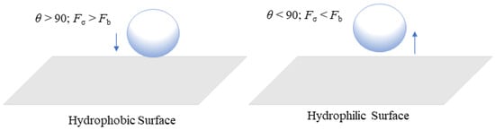
Figure 1. Formation of bubbles at hydrophobic and hydrophilic surfaces.
During the process of electrolysis, bubbles can generate motion in the surrounding liquid, which can improve mixing and mass transfer rates [26][35]. Identifying how bubbles behave will help a cell function better, allowing for the detection of any detrimental effects on the system and the development of new, innovative electrochemical technologies that will lead to more sustainable and effective energy [36]. The different operating conditions such as current density, temperature, and water flow rate can also impact the stability of the PEMWE system. Based on PEMWE modeling, it has been established that the performance of a cell is dependent on the amount of water input and that both temperature and liquid flow rate can affect current density [37][38]. As the liquid flow rate increases, larger bubbles will disperse into smaller sizes, resulting in a reduction in slug flow. However, as current density and temperature increase, larger bubbles and longer slugs will form inside the cell. With an increase in current density, a substantial number of bubbles will amalgamate, resulting in the production and wide distribution of gas bubbles. This causes bubbles to migrate toward their larger neighbors, resulting in rapid growth [39]. When flow velocity increases, bubbles begin to move faster, causing large slug gas to split up and move along the flow velocity. Li et al. [40] and Ojong et al. [41] have shown that a higher liquid velocity on the anode side can facilitate bubble separation, thus reducing mass transport loss. Therefore, understanding bubble behavior is critical for improving the mobility of this process. This understanding will aid in the development of more effective and efficient electrochemical systems for the PEM electrolysis process.
When a voltage is supplied during the water electrolysis process, then O2 and H2 bubbles are produced on the anode and cathode sides, respectively. The movement of bubbles is influenced by factors including buoyancy, surface tension, and drag force. The O2 bubbles are formed on the catalyst surface and start to grow until they reach the critical size and get detached away in the flow channel through the PTL. In most studies, water is supplied toward the anode. However, in some cases, water is also passed via the cathode-side channel to prevent the degradation of the membrane [28][42][43]. The following section discusses bubble dynamics in PEMWE with different components.
2. Bubble Dynamics in Flow Channels
The flow channel is an important structure used for designing the PEM water electrolysis. In PEM water electrolysis, various flow channels have been used for study, including serpentine, parallel, pin-type, interdigitated, mesh-type, and cascade channels [14][21][37][44]. In comparison with serpentine flow, the parallel field performs better at low pressure drop with constant flow velocity and lesser turbulence, which can increase corrosion resistance [45]. Polarization curves for various channels, including single and dual serpentine flow (SF) and parallel flow (PF) fields, have shown that more parallel channels can lead to more effective system performance [28][46]. A dual serpentine flow field is advantageous with respect to pressure drop, temperature, and current density distribution because it allows more reactants to penetrate porous layers and increase system reaction [47]. It has been found that a serpentine channel with a longer flow field produces elongated gas bubbles that can block the flow channel [37]. That research showed that, when SF and PF were compared at the same water flow, PF performed better than SF, especially at higher current densities. In the case of the SF, an annular regime was observed at high current densities. This caused the gas bubble to occupy the entire channel length, resulting in water obstruction across the LGDL and minimizing cell performance. O2 deposition in the channel may increase pressure drop and impede the system’s nonuniform temperature and current flow [37]. They also mentioned that while designing the flow field, significant attention must be considered for pressure drop management. The circuit board was printed, and the bubble flow was observed to investigate the current density along the system [48]. Those studies showed that the removal of gas bubbles from the electrode surface and the movement of water flow were significantly influenced by the presence of larger bubbles. This operation from smaller bubbles to larger bubbles enhanced mass transport results due to an increase in uniform current distribution across the channel. To maintain the two-phase flow as a bubbly flow, an ideal flow rate is required to enhance mass transfer and minimize overvoltage concentration [28]. Ojong et al. [41] stated that when only a BPP is used without a flow channel, pressure drop increases and the bubble formed tends to deposit throughout the PTL surface. This bubble accumulation had an adverse effect on mass transfer within the cell. Bubble motion inside the parallel channel gets restricted at a high current density. Stagnant bubbles covered almost the whole channel length and made it more difficult to remove the gas [23]. Deposition of O2 gas bubble in a serpentine channel is more severe than in a parallel channel due to the formation of a long slug [37]. The long slug flow caused a significant amount of gas bubbles to build along the channel, which considerably slowed down the movement of water and degraded system performance [39].
One study indicated that cascaded flow channels used on the anode side performed better than serpentine and parallel channels due to the low deposition of bubbles across the field [44]. Lafmejani et al. [49] studied both single-phase and two-phase flow by injecting blue ink along the water flow and observing how it behaves in the mesh channel. The presence of the bubble along a vertical path was shown to be favorable for liquid flow. An interdigital field channel analysis of single- and two-phase flow models was performed to understand the influence of gas bubbles on the geometry structure of the anode [50][51]. It showed that unequal flow and temperature distribution in the cell was due to the equal land width of the flow field and the presence of a gas bubble at the exit phase. Maier et al. [52] used a non-invasive technique termed acoustic emission for tracking the movement of bubbles in the flow channel and this allowed them to record system changes such as the shifting of tiny bubbles to larger bubbles and changes in bubble shape in the cell. A square-shaped pin-type channel showed a consistent distribution of temperature and current, resulting in effective elimination of gas bubbles [53].
Zhang et al. [54] found that the impact of H2 bubbles on stainless steel (SS) mesh is influenced by the current density, mesh diameter, and pore size. They also found that the SS mesh performed better than the expanded mesh as a catalyst for hydrogen evolution.
3. Bubble Dynamics in a Catalyst Layer
Metals such as Pt are commonly coated on the cathode side of the catalyst for examining the hydrogen evolution reaction (HER), whereas IrOx is loaded on the anode-side region of the catalyst for studying the oxygen evolution reaction (OER) for coating on the membrane (CCM) [55]. However, these metals are not cost-friendly when they are used for upscaling. In addition, the use of Pt metal can be poisonous when chemicals such as sulfide (commonly found in wastewater) are used [56][57]. Nonmetal catalysts such as metal sulfide, metal carbides, and metal phosphides have been used as HER catalysts in acidic conditions [58][59][60][61]. However, these nonmetals have numerous downsides, such as consuming higher voltage energy and exhibiting weaker stability when they are subjected to higher current densities [62][63][64][65][66]. Contrary to conventional Pt and other nonmetal catalysts, a Fe-N-C catalyst has been designed for HER, showing high onset [67]. Hybrid catalysts such as CoMnP/Ni2P/NF showed significant activity for HER with low overpotentials in both acidic and alkaline environments [68]. This CoMnP/Ni2P/NF exhibits superaerophobic behavior when it is studied underwater with a high contact angle of 158° and a negligible adhesive force between the bubble and the electrode surface. During the operation of electrolysis, some cathode and anode surfaces are covered by hydrogen and oxygen gas bubbles. The diameter of these bubbles can be measured by taking two elements into account: liquid surface tension and pressure difference at the meniscus. Relationships between liquid properties, pressure difference, and bubble size can be presented as follows [69]:
where Pi is the pressure inside the gas bubble, and P0 is the external pressure which is influenced by the height and the density of a liquid.
The performance and durability of the anode-side catalyst and anode plate are important to consider especially when it operates at a higher voltage to produce O2 on the anode [70]. Simply focusing on the OER may not be sufficient to prevent the catalyst from corrosion resistance [71]. They also suggested having a thorough knowledge based on different surfaces against catalyst erosion. This further understanding is essential for developing the catalyst, which not only can exhibit its life expectancy but also may resist corrosion, preventing the catalyst from leaching over time. The bubble interaction at high voltage can result in the leaching of coated catalyst material. Catalyst leaching studies were carried out for different catalyst loading, and particularly on the anode side with lower catalyst loading lower catalyst loading (0.34 mg cm−2) led to higher degradation rates compared to higher loading (1.27 mg cm−2) [72]. They stated that catalyst loading has a substantial influence on the degradation rate. If the catalyst loading is insufficient, it may fail to resist the elevated heat and ultimately it could break the catalyst material causing catalyst leaching. Compared to an MEA with low catalyst loading, an optimal loading lifespan is three times higher, which can decrease catalyst leaching and increase catalyst efficiency [73]. This nonlinear mechanical stress results specifically due to fluctuating energy supply, which in turn can cause nonuniform bubbles in electrodes that may affect the electrochemical reaction in the system [74].
Bubbles formed in the CL must exit the system via the porous transport layer (PTL) and the flow field channel [75]. Controlling the ideal catalyst loading thickness is essential for ensuring free water flow within the layer [76]. The cracks in the CL during the reaction process may lead to a negative impact on bubble management. These cracks may cause irregular and uncontrolled bubble nucleation, disrupting efficient gas transfer and system performance [77][78]. In CL, another type of surface structure known as superaerophobic surface structure serves to control gas bubbles on the OER and HER sides. This superaerophobic structure resembles an array and inhibits the bubble from adhering to the CL for an extended period [68]. For quick removal of H2 gas bubbles from the electrode surface, hybrid catalysts called FG-WS2 and VGNHs-WS2 have been employed and researchers measured their bubble size distributions (BDS) [79]. The VGNHs-WS2 hybrid catalyst produced smaller and more uniform bubbles than the FG-WS2 hybrid catalyst, which was attributed to the nanorough surface of the VGNHs. As a result, the H2 gas bubble in the electrode can escape from the HER area faster. The Pt nanoarray shape that resembled pine showed a higher contact angle. As a result, the H2 bubble detached quickly from the electrode surface [80]. When two hybrid coated catalysts were used, namely, MoS2 flat film and MoS2 nanoplatelets array, the flat film showed higher adhesive force, resulting in higher bubble attachment [81]. The MoS2 nanoplatelets array exhibited significant bubble management with a higher bubble contact angle and thus detached bubbles faster on the surface. Han et al. [82] employed a hybrid catalyst to analyze the HER reaction side by using an N-WC nanoarray and flat N-WC. When the bubble contact angle increased from 148° (flat) to 163° (N-WC nanoarray), the N-WC nanoarray demonstrated improved bubble management with respect to the flat N-WC and detached bubble size decreased from 15 µm to 5 µm. The nanoarray structure produced a smaller bubble, a larger contact angle, and a lower adhesive force. The researchers examined two distinct catalysts, and in the first set, they coated Ir-C on the anode and nitrogen-tungsten carbide (N-WC) at 1.5 V. In the other set, they coated single non-noble metal catalyst N-WC on both the anode side and the cathode side at 1.4 V. They found that using N-WC non-noble metal as a bifunctional catalyst on both the anode and cathode sides could increase the yield of the water-splitting process at a low voltage. Thus, maintaining efficient electrolysis relies significantly on managing bubbles on the HER and OER reaction sides of the CL.
On the anode, two different cost-effective catalyst coatings were performed using honeycomb Ir and dense Ir. Their comparison showed that honeycomb Ir has better bubble management due to the interconnected structures which enabled fast bubble discharge and effective water diffusion [83]. At a current density of 200 mA/cm2, the honeycomb catalyst layer outperformed the dense layer in terms of bubble nucleation and detachment times. The formation of gas bubbles in the CL alone was insufficient to optimize cell performance. However, how these bubbles are circulated within the cell plays a significant role in determining the overall voltage loss in the cell. This voltage is lost due to an accumulation of O2 bubbles on the anode side [84]. The O2 bubble generated on the CL takes more time to travel through the PTL when the applied current density is high, and the bubble transport is low. As a result, gas removal becomes very slow, and more bubbles build on the anode region [85][86]. Furthermore, the presence of the ionomer in the CL determined cell performance. The higher the ionomer in the CL, the more mass transfer losses, resulting in inefficient O2 bubble transfer [87]. This obstruction impedes efficient bubble reduction and degrades cell efficiency [88].
4. Bubble Dynamics in Porous Transport Layers
A porous transport layer (PTL), also known as a liquid gas diffusion layer (LGDL), can be utilized on the anode side with a gas diffusion layer (GDL) on the cathode side. It aids in the stability of several components such as membrane, collecting current, and counter flow of gas and water [89]. The PTL with a porosity between 30% and 50% performs well for gas bubbles to navigate faster and regular flow of intake water [90][91]. If larger pores are present in the PTL interface, they can cause insufficient contact between catalyst nanoparticles and the PTL material [92]. Recently, a novel sponge-like material with small holes known as through-pores has been developed to easily move water and gas bubbles by avoiding the longer route in the PTL [93]. After examining the behavior of gas bubbles in the PTL flow field using an X-ray imaging approach, it was found that bubble growth and detachment using the through-pores occurred more quickly than those through conventional pores. Although gas bubbles developed along the boundary between the CL and the PTL, they ended up migrating through pores toward the PTL surface [94].
When these bubbles merges with neighboring bubbles, its volume and surface energy are increased, and when it reaches the critical size, it breaks from the nucleation zone [95]. For an efficient gas bubble transfer, it is critical to minimize gas accumulation on the CL. This can be accomplished by employing a suitable PTL, which provides a conduit for gas bubbles to migrate away from the anode CL [96]. At a higher current supply, O2 gas bubbles generated in the PTL can block the flow of water toward the anode CL, resulting in water supply deficiency [24][97]. To effectively deliver water to the anode side, the PTL’s pores need to be larger, followed by a thicker catalyst coating [98]. The pore size and the thickness of the CL can significantly influence the PTL in a cell. Resistance increases with a decrease in the thickness of the CL because a thinner CL causes more restriction of electrons [99]. Additionally, Miličić et al. [100] reported that by increasing the liquid flow rate, the PTL liquid saturation is enhanced because of the efficient removal of gas bubbles from the PTL, which can reduce gas deposition in both the PTL and the anode CL. The most common materials used for fabrication of the PTL on the anode side include Ti mesh, sintered powder, felt, multilayered, perforated plates, and others [93][101][102]. These materials have excellent chemical and mechanical stability [103]. Understanding the behavior of the bubble in the porous transport layer (PTL) becomes crucial to minimize voltage loss, increase efficiency, and improve the performance of the cell’s durability. A real-time study for gas bubbles showed that at time t = 0 ms, the bubble size diameter was 70 µm. By increasing the time t to 900 ms, the bubble size increased to 130 µm [104]. Understanding how gas bubbles travel in the PTL in real time can assist in determining factors that impact mass transport and optimize the PTL structure to improve system efficiency. Furthermore, analysis of how voltage fluctuates over time at a high current density has revealed that the commercial PTL experiences a quick increase in voltage due to inadequate removal of gas bubbles at reaction sites [93].
References
- Gür, T.M. Review of Electrical Energy Storage Technologies, Materials and Systems: Challenges and Prospects for Large-Scale Grid Storage. Energy Environ. Sci. 2018, 11, 2696–2767.
- Pivovar, B.; Rustagi, N.; Satyapal, S. Hydrogen at Scale (H2@ Scale): Key to a Clean, Economic, and Sustainable Energy System. Electrochem. Soc. Interface 2018, 27, 47.
- Falcão, D.S.; Pinto, A. A Review on PEM Electrolyzer Modelling: Guidelines for Beginners. J. Clean. Prod. 2020, 261, 121184.
- Kazim, A.; Veziroglu, T.N. Utilization of Solar-Hydrogen Energy in the UAE to Maintain Its Share in the World Energy Market for the 21st Century. Renew. Energy 2001, 24, 259–274.
- Li, Y.; Yang, G.; Yu, S.; Kang, Z.; Talley, D.A.; Zhang, F.-Y. Direct Thermal Visualization of Micro-Scale Hydrogen Evolution Reactions in Proton Exchange Membrane Electrolyzer Cells. Energy Convers. Manag. 2019, 199, 111935.
- Lim, H. Hydrogen Selectivity and Permeance Effect on the Water Gas Shift Reaction (WGSR) in a Membrane Reactor. Korean J. Chem. Eng. 2015, 32, 1522–1527.
- Muthukumar, M.; Rengarajan, N.; Velliyangiri, B.; Omprakas, M.A.; Rohit, C.B.; Raja, U.K. The Development of Fuel Cell Electric Vehicles-A Review. Mater. Today Proc. 2021, 45, 1181–1187.
- Bruce, S.; Temminghoff, M.; Hayward, J.; Schmidt, E.; Munnings, C.; Palfreyman, D.; Hartley, P. National Hydrogen Roadmap; CSIRO: Canberra, Australia, 2018; Available online: www.csiro.au (accessed on 23 August 2018).
- Glenk, G.; Reichelstein, S. Economics of Converting Renewable Power to Hydrogen. Nat. Energy 2019, 4, 216–222.
- Hadikhani, P.; Hashemi, S.M.H.; Schenk, S.A.; Psaltis, D. A Membrane-Less Electrolyzer with Porous Walls for High Throughput and Pure Hydrogen Production. Sustain. Energy Fuels 2021, 5, 2419–2432.
- Ren, Z.; Wang, J.; Yu, Z.; Zhang, C.; Gao, S.; Wang, P. Experimental Studies and Modeling of a 250-KW Alkaline Water Electrolyzer for Hydrogen Production. J. Power Sources 2022, 544, 231886.
- Falcão, D.S. Green Hydrogen Production by Anion Exchange Membrane Water Electrolysis: Status and Future Perspectives. Energies 2023, 16, 943.
- Mo, J.; Kang, Z.; Yang, G.; Li, Y.; Retterer, S.T.; Cullen, D.A.; Toops, T.J.; Bender, G.; Pivovar, B.S.; Green, J.B.; et al. In Situ Investigation on Ultrafast Oxygen Evolution Reactions of Water Splitting in Proton Exchange Membrane Electrolyzer Cells. J. Mater. Chem. A Mater. 2017, 5, 18469–18475.
- Lin, R.; Lu, Y.; Xu, J.; Huo, J.; Cai, X. Investigation on Performance of Proton Exchange Membrane Electrolyzer with Different Flow Field Structures. Appl. Energy 2022, 326, 120011.
- Fallah Vostakola, M.; Ozcan, H.; El-Emam, R.S.; Amini Horri, B. Recent Advances in High-Temperature Steam Electrolysis with Solid Oxide Electrolysers for Green Hydrogen Production. Energies 2023, 16, 3327.
- Carmo, M.; Fritz, D.L.; Mergel, J.; Stolten, D. A Comprehensive Review on PEM Water Electrolysis. Int. J. Hydrogen Energy 2013, 38, 4901–4934.
- Li, Y.; Kang, Z.; Mo, J.; Yang, G.; Yu, S.; Talley, D.A.; Han, B.; Zhang, F.Y. In-Situ Investigation of Bubble Dynamics and Two-Phase Flow in Proton Exchange Membrane Electrolyzer Cells. Int. J. Hydrogen Energy 2018, 43, 11223–11233.
- Mo, J.; Kang, Z.; Retterer, S.T.; Cullen, D.A.; Toops, T.J.; Green, J.B.; Mench, M.M.; Zhang, F.-Y. Discovery of True Electrochemical Reactions for Ultrahigh Catalyst Mass Activity in Water Splitting. Sci. Adv. 2016, 2, e1600690.
- Feng, Q.; Liu, G.; Wei, B.; Zhang, Z.; Li, H.; Wang, H. A Review of Proton Exchange Membrane Water Electrolysis on Degradation Mechanisms and Mitigation Strategies. J. Power Sources 2017, 366, 33–55.
- Lettenmeier, P.; Wang, R.; Abouatallah, R.; Helmly, S.; Morawietz, T.; Hiesgen, R.; Kolb, S.; Burggraf, F.; Kallo, J.; Gago, A.S. Durable Membrane Electrode Assemblies for Proton Exchange Membrane Electrolyzer Systems Operating at High Current Densities. Electrochim. Acta 2016, 210, 502–511.
- Ito, H.; Maeda, T.; Nakano, A.; Hwang, C.M.; Ishida, M.; Kato, A.; Yoshida, T. Experimental Study on Porous Current Collectors of PEM Electrolyzers. Int. J. Hydrogen Energy 2012, 37, 7418–7428.
- Su, X.; Xu, L.; Hu, B. Simulation of Proton Exchange Membrane Electrolyzer: Influence of Bubble Covering. Int. J. Hydrogen Energy 2022, 47, 20027–20039.
- Maier, M.; Meyer, Q.; Majasan, J.; Owen, R.E.; Robinson, J.B.; Dodwell, J.; Wu, Y.; Castanheira, L.; Hinds, G.; Shearing, P.R.; et al. Diagnosing Stagnant Gas Bubbles in a Polymer Electrolyte Membrane Water Electrolyser Using Acoustic Emission. Front. Energy Res. 2020, 8, 582919.
- Nouri-Khorasani, A.; Tabu Ojong, E.; Smolinka, T.; Wilkinson, D.P. Model of Oxygen Bubbles and Performance Impact in the Porous Transport Layer of PEM Water Electrolysis Cells. Int. J. Hydrogen Energy 2017, 42, 28665–28680.
- Kadyk, T.; Bruce, D.; Eikerling, M. How to Enhance Gas Removal from Porous Electrodes? Sci. Rep. 2016, 6, 38780.
- Vogt, H.; Stephan, K. Local Microprocesses at Gas-Evolving Electrodes and Their Influence on Mass Transfer. Electrochim. Acta 2015, 155, 348–356.
- Vassie, P.R.; Tseung, A.C.C. A Study of Gas Evolution in Teflon Bonded Porous Electrodes-I: The Mechanical and Chemical Stability of Teflon Bonded Graphite Electrodes. Electrochim. Acta 1975, 20, 759–761.
- Ito, H.; Maeda, T.; Nakano, A.; Hasegawa, Y.; Yokoi, N.; Hwang, C.M.; Ishida, M.; Kato, A.; Yoshida, T. Effect of Flow Regime of Circulating Water on a Proton Exchange Membrane Electrolyzer. Int. J. Hydrogen Energy 2010, 35, 9550–9560.
- Wang, W.; Yu, S.; Li, K.; Ding, L.; Xie, Z.; Li, Y.; Yang, G.; Cullen, D.A.; Yu, H.; Kang, Z.; et al. Insights into the Rapid Two-Phase Transport Dynamics in Different Structured Porous Transport Layers of Water Electrolyzers through High-Speed Visualization. J. Power Sources 2021, 516, 230641.
- Butterworth, D.; Hewitt, G.F. Two-Phase Flow and Heat Transfer; Oxford University Press: Oxford, UK; New York, NY, USA, 1977; pp. 18–39.
- Chien, S.-F.; Ibele, W. Pressure Drop and Liquid Film Thickness of Two-Phase Annular and Annular-Mist Flows. J. Heat Transf. 1964, 86, 89–96.
- Sakuma, G.; Fukunaka, Y.; Matsushima, H. Nucleation and Growth of Electrolytic Gas Bubbles under Microgravity. Int. J. Hydrogen Energy 2014, 39, 7638–7645.
- Jiang, Y.; Li, Y.; Ding, Y.; Hu, S.; Dang, J.; Yang, F.; Ouyang, M. Simulation and Experiment Study on Two-Phase Flow Characteristics of Proton Exchange Membrane Electrolysis Cell. J. Power Sources 2023, 553, 232303.
- Mo, J. Fundamental Studies of Electrochemical Reactions and Microfluidics in Proton Exchange Membrane Electrolyzer Cells. Ph.D. Dissertation, University of Tennessee, Knoxville, TN, USA, 2016.
- Yang, X.; Karnbach, F.; Uhlemann, M.; Odenbach, S.; Eckert, K. Dynamics of Single Hydrogen Bubbles at a Platinum Microelectrode. Langmuir 2015, 31, 8184–8193.
- Angulo, A.; van der Linde, P.; Gardeniers, H.; Modestino, M.; Fernández Rivas, D. Influence of Bubbles on the Energy Conversion Efficiency of Electrochemical Reactors. Joule 2020, 4, 555–579.
- Majasan, J.O.; Cho, J.I.S.; Dedigama, I.; Tsaoulidis, D.; Shearing, P.; Brett, D.J.L. Two-Phase Flow Behaviour and Performance of Polymer Electrolyte Membrane Electrolysers: Electrochemical and Optical Characterisation. Int. J. Hydrogen Energy 2018, 43, 15659–15672.
- Wang, Z.; Wang, X.; Chen, Z.; Liao, Z.; Xu, C.; Du, X. Energy and Exergy Analysis of a Proton Exchange Membrane Water Electrolysis System without Additional Internal Cooling. Renew. Energy 2021, 180, 1333–1343.
- Li, Y.; Yang, G.; Yu, S.; Kang, Z.; Mo, J.; Han, B.; Talley, D.A.; Zhang, F.Y. In-Situ Investigation and Modeling of Electrochemical Reactions with Simultaneous Oxygen and Hydrogen Microbubble Evolutions in Water Electrolysis. Int. J. Hydrogen Energy 2019, 44, 28283–28293.
- Li, H.; Inada, A.; Fujigaya, T.; Nakajima, H.; Sasaki, K.; Ito, K. Effects of Operating Conditions on Performance of High-Temperature Polymer Electrolyte Water Electrolyzer. J. Power Sources 2016, 318, 192–199.
- Ojong, E.T.; Kwan, J.T.H.; Nouri-Khorasani, A.; Bonakdarpour, A.; Wilkinson, D.P.; Smolinka, T. Development of an Experimentally Validated Semi-Empirical Fully-Coupled Performance Model of a PEM Electrolysis Cell with a 3-D Structured Porous Transport Layer. Int. J. Hydrogen Energy 2017, 42, 25831–25847.
- Bonanno, M.; Müller, K.; Bensmann, B.; Hanke-Rauschenbach, R.; Peach, R.; Thiele, S. Evaluation of the Efficiency of an Elevated Temperature Proton Exchange Membrane Water Electrolysis System. J. Electrochem. Soc. 2021, 168, 094504.
- Moon, J.W.; Kim, S.K.; Jung, S.Y. In-Situ Visualization of Cathode Flow Channel in Polymer Electrolyte Membrane Fuel Cell: Effect of GDL Degradation. Int. J. Hydrogen Energy 2023, in press.
- Li, H.; Nakajima, H.; Inada, A.; Ito, K. Effect of Flow-Field Pattern and Flow Configuration on the Performance of a Polymer-Electrolyte-Membrane Water Electrolyzer at High Temperature. Int. J. Hydrogen Energy 2018, 43, 8600–8610.
- Tijani, A.S.; Barr, D.; Rahim, A.H.A. Computational Modelling of the Flow Field of an Electrolyzer System Using CFD. Energy Procedia 2015, 79, 195–203.
- Lee, B.; Park, K.; Kim, H.-M. Dynamic Simulation of PEM Water Electrolysis and Comparison with Experiments. Int. J. Electrochem. Sci. 2013, 8, 235–248.
- Toghyani, S.; Afshari, E.; Baniasadi, E.; Atyabi, S.A. Thermal and Electrochemical Analysis of Different Flow Field Patterns in a PEM Electrolyzer. Electrochim. Acta 2018, 267, 234–245.
- Dedigama, I.; Angeli, P.; Van Dijk, N.; Millichamp, J.; Tsaoulidis, D.; Shearing, P.R.; Brett, D.J.L. Current Density Mapping and Optical Flow Visualisation of a Polymer Electrolyte Membrane Water Electrolyser. J. Power Sources 2014, 265, 97–103.
- Lafmejani, S.S.; Müller, M.; Olesen, A.C.; Kær, S.K. Experimental and Numerical Study of Flow in Expanded Metal Plate for Water Electrolysis Applications. J. Power Sources 2018, 397, 334–342.
- Olesen, A.C.; Rømer, C.; Kær, S.K. A Numerical Study of the Gas-Liquid, Two-Phase Flow Maldistribution in the Anode of a High Pressure PEM Water Electrolysis Cell. Int. J. Hydrogen Energy 2016, 41, 52–68.
- Olesen, A.C.; Frensch, S.H.; Kær, S.K. Towards Uniformly Distributed Heat, Mass and Charge: A Flow Field Design Study for High Pressure and High Current Density Operation of PEM Electrolysis Cells. Electrochim. Acta 2019, 293, 476–495.
- Maier, M.; Meyer, Q.; Majasan, J.; Tan, C.; Dedigama, I.; Robinson, J.; Dodwell, J.; Wu, Y.; Castanheira, L.; Hinds, G. Operando Flow Regime Diagnosis Using Acoustic Emission in a Polymer Electrolyte Membrane Water Electrolyser. J. Power Sources 2019, 424, 138–149.
- Minnaar, C.; De Beer, F.; Bessarabov, D. Current Density Distribution of Electrolyzer Flow Fields: In Situ Current Mapping and Neutron Radiography. Energy Fuels 2020, 34, 1014–1023.
- Zhang, Y.; Merrill, M.D.; Logan, B.E. The Use and Optimization of Stainless Steel Mesh Cathodes in Microbial Electrolysis Cells. Int. J. Hydrogen Energy 2010, 35, 12020–12028.
- Watanabe, K.; Wakuda, K.; Wani, K.; Araki, T.; Nagasawa, K.; Mitsushima, S. Existence of Dissolved Oxygen near Anode Catalyst in Proton Exchange Membrane Water Electrolyzers. J. Electrochem. Soc. 2022, 169, 044515.
- Logan, B.E.; Call, D.; Cheng, S.; Hamelers, H.V.M.; Sleutels, T.H.J.A.; Jeremiasse, A.W.; Rozendal, R.A. Microbial Electrolysis Cells for High Yield Hydrogen Gas Production from Organic Matter. Environ. Sci. Technol. 2008, 42, 8630–8640.
- Ayers, K.E.; Renner, J.N.; Danilovic, N.; Wang, J.X.; Zhang, Y.; Maric, R.; Yu, H. Pathways to Ultra-Low Platinum Group Metal Catalyst Loading in Proton Exchange Membrane Electrolyzers. Catal. Today 2016, 262, 121–132.
- Cheng, L.; Huang, W.; Gong, Q.; Liu, C.; Liu, Z.; Li, Y.; Dai, H. Ultrathin WS2 Nanoflakes as a High-performance Electrocatalyst for the Hydrogen Evolution Reaction. Angew. Chem. Int. Ed. 2014, 53, 7860–7863.
- Xie, J.; Zhang, H.; Li, S.; Wang, R.; Sun, X.; Zhou, M.; Zhou, J.; Lou, X.W.; Xie, Y. Defect-rich MoS2 Ultrathin Nanosheets with Additional Active Edge Sites for Enhanced Electrocatalytic Hydrogen Evolution. Adv. Mater. 2013, 25, 5807–5813.
- Kornienko, N.; Resasco, J.; Becknell, N.; Jiang, C.-M.; Liu, Y.-S.; Nie, K.; Sun, X.; Guo, J.; Leone, S.R.; Yang, P. Operando Spectroscopic Analysis of an Amorphous Cobalt Sulfide Hydrogen Evolution Electrocatalyst. J. Am. Chem. Soc. 2015, 137, 7448–7455.
- Lu, S.; Zhuang, Z. Electrocatalysts for Hydrogen Oxidation and Evolution Reactions. Sci. China Mater. 2016, 3, 217–238.
- Shi, J.; Ma, L.; Wu, P.; Zhou, Z.; Guo, P.; Shen, S.; Jing, D.; Guo, L. A Novel Sn2Sb2O7 Nanophotocatalyst for Visible-Light-Driven H2 Evolution. Nano Res. 2012, 5, 576–583.
- Fan, X.; Zhou, H.; Guo, X. WC Nanocrystals Grown on Vertically Aligned Carbon Nanotubes: An Efficient and Stable Electrocatalyst for Hydrogen Evolution Reaction. ACS Nano 2015, 9, 5125–5134.
- Ma, R.; Zhou, Y.; Chen, Y.; Li, P.; Liu, Q.; Wang, J. Ultrafine Molybdenum Carbide Nanoparticles Composited with Carbon as a Highly Active Hydrogen-evolution Electrocatalyst. Angew. Chem. 2015, 127, 14936–14940.
- Zhou, H.; Wang, Y.; He, R.; Yu, F.; Sun, J.; Wang, F.; Lan, Y.; Ren, Z.; Chen, S. One-Step Synthesis of Self-Supported Porous NiSe2/Ni Hybrid Foam: An Efficient 3D Electrode for Hydrogen Evolution Reaction. Nano Energy 2016, 20, 29–36.
- Li, F.; Li, J.; Lin, X.; Li, X.; Fang, Y.; Jiao, L.; An, X.; Fu, Y.; Jin, J.; Li, R. Designed Synthesis of Multi-Walled Carbon Nanotubes@ Cu@MoS2 Hybrid as Advanced Electrocatalyst for Highly Efficient Hydrogen Evolution Reaction. J. Power Sources 2015, 300, 301–308.
- Liu, S.; Meyer, Q.; Jia, C.; Wang, S.; Rong, C.; Nie, Y.; Zhao, C. Operando Deconvolution of the Degradation Mechanisms of Iron–Nitrogen–Carbon Catalysts in Proton Exchange Membrane Fuel Cells. Energy Environ. Sci. 2023, 16, 3792–3802.
- Liu, M.; Sun, Z.; Li, S.; Nie, X.; Liu, Y.; Wang, E.; Zhao, Z. Hierarchical Superhydrophilic/Superaerophobic CoMnP/Ni2P Nanosheet-Based Microplate Arrays for Enhanced Overall Water Splitting. J. Mater. Chem. A Mater. 2021, 9, 22129–22139.
- Chen, Y.; Mojica, F.; Li, G.; Chuang, P.Y.A. Experimental Study and Analytical Modeling of an Alkaline Water Electrolysis Cell. Int. J. Energy Res. 2017, 41, 2365–2373.
- Jung, G.; Yu, J.-W.; Dlamini, M.M.; Kan, M.-Y.; Lai, C.-J.; Yeh, C.-C.; Chan, S.H. Proton Exchange Membrane Water Electrolysis-Effect of Pretreatment before Electrocoating Ti Anode Support. Int. J. Hydrogen Energy 2023, in press.
- Roy, C.; Rao, R.R.; Stoerzinger, K.A.; Hwang, J.; Rossmeisl, J.; Chorkendorff, I.; Shao-Horn, Y.; Stephens, I.E.L. Trends in Activity and Dissolution on RuO2 under Oxygen Evolution Conditions: Particles versus Well-Defined Extended Surfaces. ACS Energy Lett. 2018, 3, 2045–2051.
- Siracusano, S.; Hodnik, N.; Jovanovic, P.; Ruiz-Zepeda, F.; Šala, M.; Baglio, V.; Aricò, A.S. New Insights into the Stability of a High Performance Nanostructured Catalyst for Sustainable Water Electrolysis. Nano Energy 2017, 40, 618–632.
- Siracusano, S.; Baglio, V.; Van Dijk, N.; Merlo, L.; Aricò, A.S. Enhanced Performance and Durability of Low Catalyst Loading PEM Water Electrolyser Based on a Short-Side Chain Perfluorosulfonic Ionomer. Appl. Energy 2017, 192, 477–489.
- Rakousky, C.; Reimer, U.; Wippermann, K.; Kuhri, S.; Carmo, M.; Lueke, W.; Stolten, D. Polymer Electrolyte Membrane Water Electrolysis: Restraining Degradation in the Presence of Fluctuating Power. J. Power Sources 2017, 342, 38–47.
- Hreiz, R.; Abdelouahed, L.; Fuenfschilling, D.; Lapicque, F. Electrogenerated Bubbles Induced Convection in Narrow Vertical Cells: PIV Measurements and Euler-Lagrange CFD Simulation. Chem. Eng. Sci. 2015, 134, 138–152.
- Yuan, S.; Zhao, C.; Cai, X.; An, L.; Shen, S.; Yan, X.; Zhang, J. Bubble Evolution and Transport in PEM Water Electrolysis: Mechanism, Impact, and Management. Prog. Energy Combust. Sci. 2023, 96, 101075.
- Zeradjanin, A.R.; La Mantia, F.; Masa, J.; Schuhmann, W. Utilization of the Catalyst Layer of Dimensionally Stable Anodes-Interplay of Morphology and Active Surface Area. Electrochim. Acta 2012, 82, 408–414.
- Zeradjanin, A.R.; Ventosa, E.; Masa, J.; Schuhmann, W. Utilization of the Catalyst Layer of Dimensionally Stable Anodes. Part 2: Impact of Spatial Current Distribution on Electrocatalytic Performance. J. Electroanal. Chem. 2018, 828, 63–70.
- Akbar, K.; Hussain, S.; Truong, L.; Roy, S.B.; Jeon, J.H.; Jerng, S.-K.; Kim, M.; Yi, Y.; Jung, J.; Chun, S.-H. Induced Superaerophobicity onto a Non-Superaerophobic Catalytic Surface for Enhanced Hydrogen Evolution Reaction. ACS Appl. Mater. Interfaces 2017, 9, 43674–43680.
- Li, Y.; Zhang, H.; Xu, T.; Lu, Z.; Wu, X.; Wan, P.; Sun, X.; Jiang, L. Under-water Superaerophobic Pine-shaped Pt Nanoarray Electrode for Ultrahigh-performance Hydrogen Evolution. Adv. Funct. Mater. 2015, 25, 1737–1744.
- Lu, Z.; Zhu, W.; Yu, X.; Zhang, H.; Li, Y.; Sun, X.; Wang, X.; Wang, H.; Wang, J.; Luo, J. Ultrahigh Hydrogen Evolution Performance of Under-water “Superaerophobic” MoS2 Nanostructured Electrodes. Adv. Mater. 2014, 26, 2683–2687.
- Han, N.; Yang, K.R.; Lu, Z.; Li, Y.; Xu, W.; Gao, T.; Cai, Z.; Zhang, Y.; Batista, V.S.; Liu, W. Nitrogen-Doped Tungsten Carbide Nanoarray as an Efficient Bifunctional Electrocatalyst for Water Splitting in Acid. Nat. Commun. 2018, 9, 924.
- Ding, L.; Wang, W.; Xie, Z.; Li, K.; Yu, S.; Capuano, C.B.; Keane, A.; Ayers, K.; Zhang, F.-Y. Highly Porous Iridium Thin Electrodes with Low Loading and Improved Reaction Kinetics for Hydrogen Generation in PEM Electrolyzer Cells. ACS Appl. Mater. Interfaces 2023, 15, 24284–24295.
- Lee, C.H.; Banerjee, R.; Arbabi, F.; Hinebaugh, J.; Bazylak, A. Porous Transport Layer Related Mass Transport Losses in Polymer Electrolyte Membrane Electrolysis: A Review. In Proceedings of the International Conference on Nanochannels, Microchannels, and Minichannels, Washington, DC, USA, 10–14 July 2016; American Society of Mechanical Engineers: New York, NY, USA, 2016; Volume 50343, p. V001T07A003.
- Satjaritanun, P.; O’Brien, M.; Kulkarni, D.; Shimpalee, S.; Capuano, C.; Ayers, K.E.; Danilovic, N.; Parkinson, D.Y.; Zenyuk, I. V Observation of Preferential Pathways for Oxygen Removal through Porous Transport Layers of Polymer Electrolyte Water Electrolyzers. iScience 2020, 23, 101783.
- Lee, C.; Hinebaugh, J.; Banerjee, R.; Chevalier, S.; Abouatallah, R.; Wang, R.; Bazylak, A. Influence of Limiting Throat and Flow Regime on Oxygen Bubble Saturation of Polymer Electrolyte Membrane Electrolyzer Porous Transport Layers. Int. J. Hydrogen Energy 2017, 42, 2724–2735.
- Kulkarni, D.; Huynh, A.; Satjaritanun, P.; O’Brien, M.; Shimpalee, S.; Parkinson, D.; Shevchenko, P.; DeCarlo, F.; Danilovic, N.; Ayers, K.E. Elucidating Effects of Catalyst Loadings and Porous Transport Layer Morphologies on Operation of Proton Exchange Membrane Water Electrolyzers. Appl. Catal. B 2022, 308, 121213.
- Alia, S.M.; Reeves, K.S.; Baxter, J.S.; Cullen, D.A. The Impact of Ink and Spray Variables on Catalyst Layer Properties, Electrolyzer Performance, and Electrolyzer Durability. J. Electrochem. Soc. 2020, 167, 144512.
- Maier, M.; Dodwell, J.; Ziesche, R.; Tan, C.; Heenan, T.; Majasan, J.; Kardjilov, N.; Markötter, H.; Manke, I.; Castanheira, L.; et al. Mass Transport in Polymer Electrolyte Membrane Water Electrolyser Liquid-Gas Diffusion Layers: A Combined Neutron Imaging and X-Ray Computed Tomography Study. J. Power Sources 2020, 455, 227968.
- Grigoriev, S.A.; Millet, P.; Volobuev, S.A.; Fateev, V.N. Optimization of Porous Current Collectors for PEM Water Electrolysers. Int. J. Hydrogen Energy 2009, 34, 4968–4973.
- Ito, H.; Maeda, T.; Nakano, A.; Kato, A.; Yoshida, T. Influence of Pore Structural Properties of Current Collectors on the Performance of Proton Exchange Membrane Electrolyzer. Electrochim. Acta 2013, 100, 242–248.
- Lopata, J.; Kang, Z.; Young, J.; Bender, G.; Weidner, J.W.; Shimpalee, S. Effects of the Transport/Catalyst Layer Interface and Catalyst Loading on Mass and Charge Transport Phenomena in Polymer Electrolyte Membrane Water Electrolysis Devices. J. Electrochem. Soc. 2020, 167, 064507.
- Lee, J.K.; Lee, C.H.; Fahy, K.F.; Kim, P.J.; Krause, K.; LaManna, J.M.; Baltic, E.; Jacobson, D.L.; Hussey, D.S.; Bazylak, A. Accelerating Bubble Detachment in Porous Transport Layers with Patterned Through-Pores. ACS Appl. Energy Mater. 2020, 3, 9676–9684.
- Kim, P.J.; Lee, C.H.; Lee, J.K.; Fahy, K.F.; Bazylak, A. In-Plane Transport in Water Electrolyzer Porous Transport Layers with through Pores. J. Electrochem. Soc. 2020, 167, 124522.
- Jeon, D.H.; Kim, S.; Kim, M.J.; Lee, C.; Cho, H.S. Oxygen Bubble Transport in a Porous Transport Layer of Polymer Electrolyte Water Electrolyzer. J. Power Sources 2023, 553, 232322.
- Nie, J.; Chen, Y. Numerical Modeling of Three-Dimensional Two-Phase Gas–Liquid Flow in the Flow Field Plate of a PEM Electrolysis Cell. Int. J. Hydrogen Energy 2010, 35, 3183–3197.
- Arbabi, F.; Kalantarian, A.; Abouatallah, R.; Wang, R.; Wallace, J.S.; Bazylak, A. Feasibility Study of Using Microfluidic Platforms for Visualizing Bubble Flows in Electrolyzer Gas Diffusion Layers. J. Power Sources 2014, 258, 142–149.
- Bernt, M.; Siebel, A.; Gasteiger, H.A. Analysis of Voltage Losses in PEM Water Electrolyzers with Low Platinum Group Metal Loadings. J. Electrochem. Soc. 2018, 165, F305–F314.
- Parra-Restrepo, J.; Bligny, R.; Dillet, J.; Didierjean, S.; Stemmelen, D.; Moyne, C.; Degiovanni, A.; Maranzana, G. Influence of the Porous Transport Layer Properties on the Mass and Charge Transfer in a Segmented PEM Electrolyzer. Int. J. Hydrogen Energy 2020, 45, 8094–8106.
- Miličić, T.; Altaf, H.; Vorhauer-Huget, N.; Živković, L.A.; Tsotsas, E.; Vidaković-Koch, T. Modeling and Analysis of Mass Transport Losses of Proton Exchange Membrane Water Electrolyzer. Processes 2022, 10, 2417.
- Kang, Z.; Mo, J.; Yang, G.; Retterer, S.T.; Cullen, D.A.; Toops, T.J.; Green, J.B.; Mench, M.M.; Zhang, F.Y. Investigation of Thin/Well-Tunable Liquid/Gas Diffusion Layers Exhibiting Superior Multifunctional Performance in Low-Temperature Electrolytic Water Splitting. Energy Environ. Sci. 2017, 10, 166–175.
- Yuan, X.-Z.; Shaigan, N.; Song, C.; Aujla, M.; Neburchilov, V.; Kwan, J.T.H.; Wilkinson, D.P.; Bazylak, A.; Fatih, K. The Porous Transport Layer in Proton Exchange Membrane Water Electrolysis: Perspectives on a Complex Component. Sustain. Energy Fuels 2022, 6, 1824–1853.
- Schmidt, G.; Suermann, M.; Bensmann, B.; Hanke-Rauschenbach, R.; Neuweiler, I. Modeling Overpotentials Related to Mass Transport through Porous Transport Layers of PEM Water Electrolysis Cells. J. Electrochem. Soc. 2020, 167, 114511.
- Leonard, E.; Shum, A.D.; Normile, S.; Sabarirajan, D.C.; Yared, D.G.; Xiao, X.; Zenyuk, I.V. Operando X-Ray Tomography and Sub-Second Radiography for Characterizing Transport in Polymer Electrolyte Membrane Electrolyzer. Electrochim. Acta 2018, 276, 424–433.
More
Information
Subjects:
Energy & Fuels
Contributors
MDPI registered users' name will be linked to their SciProfiles pages. To register with us, please refer to https://encyclopedia.pub/register
:
View Times:
1.8K
Revisions:
2 times
(View History)
Update Date:
10 Jan 2024
Table of Contents


Notice
You are not a member of the advisory board for this topic. If you want to update advisory board member profile, please contact office@encyclopedia.pub.
OK
Confirm
Only members of the Encyclopedia advisory board for this topic are allowed to note entries. Would you like to become an advisory board member of the Encyclopedia?
Yes
No
${ textCharacter }/${ maxCharacter }
Submit
Cancel
Back
Comments
${ item }
|
${ item.createdUser.fullName }
${ item.createdAt }
${ item.vote }
${ item.reply }
Delete
${ reply.createdUser.fullName }
${ reply.createdAt }
${ reply.vote }
Delete
There is no reply to this comment~
${ item.replyTextCharacter }/${ item.replyMaxCharacter }
Submit
Cancel
More
No more~
There is no comment~
${ textCharacter }/${ maxCharacter }
Submit
Cancel
${ selectedItem.replyTextCharacter }/${ selectedItem.replyMaxCharacter }
Submit
Cancel
Confirm
Are you sure to Delete?
Yes
No