Your browser does not fully support modern features. Please upgrade for a smoother experience.
Submitted Successfully!
 +1 credit
Thank you for your contribution! You can also upload a video entry or images related to this topic.
For video creation, please contact our Academic Video Service.
| Version | Summary | Created by | Modification | Content Size | Created at | Operation |
|---|---|---|---|---|---|---|
| 1 | Farid Bakir | -- | 5051 | 2023-12-18 09:07:25 | | | |
| 2 | Mona Zou | Meta information modification | 5051 | 2023-12-19 10:14:32 | | | | |
| 3 | Mona Zou | Meta information modification | 5051 | 2023-12-19 10:15:27 | | | | |
| 4 | Mona Zou | Meta information modification | 5051 | 2023-12-19 10:15:58 | | |
Video Upload Options
We provide professional Academic Video Service to translate complex research into visually appealing presentations. Would you like to try it?
Cite
If you have any further questions, please contact Encyclopedia Editorial Office.
Vanaei, H.R.; Khelladi, S.; Dobrev, I.; Bakir, F.; Himeur, R.M.; Mammeri, A.; Azzouz, K. Performance and Efficiency of Cross-Flow Fans. Encyclopedia. Available online: https://encyclopedia.pub/entry/52854 (accessed on 23 July 2026).
Vanaei HR, Khelladi S, Dobrev I, Bakir F, Himeur RM, Mammeri A, et al. Performance and Efficiency of Cross-Flow Fans. Encyclopedia. Available at: https://encyclopedia.pub/entry/52854. Accessed July 23, 2026.
Vanaei, Hamid Reza, Sofiane Khelladi, Ivan Dobrev, Farid Bakir, Rania M. Himeur, Amrid Mammeri, Kamel Azzouz. "Performance and Efficiency of Cross-Flow Fans" Encyclopedia, https://encyclopedia.pub/entry/52854 (accessed July 23, 2026).
Vanaei, H.R., Khelladi, S., Dobrev, I., Bakir, F., Himeur, R.M., Mammeri, A., & Azzouz, K. (2023, December 18). Performance and Efficiency of Cross-Flow Fans. In Encyclopedia. https://encyclopedia.pub/entry/52854
Vanaei, Hamid Reza, et al. "Performance and Efficiency of Cross-Flow Fans." Encyclopedia. Web. 18 December, 2023.
Copy Citation
Cross-Flow Fans (CFFs) have been widely applied in the automotive and domestic air conditioning industries in recent decades. They are high-pressure coefficient turbomachines compacted diametrically, and thus, the complex interactions of these fans require thorough evaluation. Their innovation has opened up new directions in turbomachinery, and both academic research and industry have seen numerous efforts to develop these types of fans. Despite extensive work, optimizing and improving their performance remains a challenge. Enhancing their efficiency necessitates improvements in structural characteristics, aerodynamic features, and acoustic properties.
cross-flow fan
turbomachinery
aerodynamics
aeroacoustics
performance
1. Correlation of Design Parameters and Performance in CFFs
Numerous research studies have primarily focused on examining the design parameters that affect the efficiency and performance of Cross-Flow Fans (CFFs). Over time, a diverse range of CFF variants has been meticulously developed and successfully applied across various industries. However, in line with the previous section, there is a noticeably increasing commitment to comprehensively evaluate the impact of different design parameters on CFF performance. This growing emphasis on scrutinizing design parameter influence underscores the increasing recognition of the importance of fine-tuning CFFs to meet the specific requirements of various applications. Such research not only contributes to the continuous improvement of CFF designs but also enables their more efficient and effective utilization in a variety of industrial and engineering contexts.
In reference to the work conducted by Lazzaretto [1], a specific criterion has been established to define the geometric variables necessary for characterizing fan performance, both in experimental and numerical settings. This criterion serves as a fundamental guideline for evaluating and optimizing fan designs. Eck et al. [2] employed a one-dimensional theoretical model that involved an analysis of blade cascades. Through their research, they identified specific values for 𝛽1 and 𝛽2
, representing the internal and external blade angles, respectively. Notably, they observed that reducing the external blade angle can enhance the total pressure coefficient, with a primary emphasis on the external blade angle rather than variations in the internal blade angle. However, other researchers have proposed a more comprehensive range of blade angles for optimization, considering both internal and external blades [3][4]. Murata et al. [5] contributed to this understanding by emphasizing the significance of evaluating the gap between components and the setting angle, as these factors also significantly affect fan performance. Taking an overarching view of the findings from Tanaka and Matsuki’s numerical simulations [6][7], it becomes evident that specific blade Reynolds numbers play a pivotal role in influencing flow viscosity, while the dimensions of the impeller also have a significant impact on fan performance. These collective insights form the basis for refining and optimizing fan designs, contributing to the ongoing enhancement of fan efficiency and effectiveness.
Kim et al. [8] embarked on a comprehensive examination of the interplay between the flow field and, by extension, the performance of Cross-Flow Fans (CFFs). To elucidate the intricate relationship between these elements and the design parameters, they embarked on a computational journey. Their approach involved solving a two-dimensional unsteady governing equation, a mathematical representation of the fluid dynamics at play, employing the Finite Volume Method (FVM). This computational method is a powerful tool for simulating fluid flow and heat transfer in complex systems. A notable aspect of their methodology was the utilization of a sliding grid system, which enables dynamic grid adjustments to capture the evolving geometry of the flow field. This flexibility in grid adaptation is particularly advantageous when dealing with rotating machinery, such as CFFs. Additionally, they incorporated the standard k-𝜖 turbulence model, a well-established model in fluid dynamics, to simulate turbulence effects in the flow field accurately. This choice allowed them to capture the intricate details of the velocity profile around the impeller. Importantly, they conducted these simulations while maintaining a constant rotating speed but varying the design parameters. This approach enabled them to systematically investigate the impact of different design choices on the velocity distribution around the impeller. By systematically exploring these variables, Kim and their team could provide valuable insights into the performance characteristics of CFFs and how they relate to design parameters. Their work contributes significantly to the understanding of CFF behavior and informs the ongoing refinement of these fans for various applications.
As briefly stated, Lazzaretto et al. [1] introduced an original criterion that primarily concerns the selection of geometric variables, particularly related to the impeller geometry and shape. Although their primary focus revolved around the casing geometry, their approach provides a valuable roadmap for enhancing design and improving efficiency. This criterion, as proposed by Lazzaretto et al., serves as a guiding principle, offering a structured method for making informed decisions regarding the geometry of the impeller and its casing. It lays the groundwork for optimizing the performance of fans, particularly Cross-Flow Fans (CFFs), and enhancing their overall efficiency. Furthermore, Tanaka and Murata have made significant contributions to the field by employing Laser Doppler Velocimeter (LDV) measurements to assess the velocity field and determine static pressure distributions in CFFs. Through their work, they uncovered a distinctive scale effect within the flow dynamics. As they increased the rotor size, they observed changes in vorticity and pressure drop within the eccentric vortex. This scale effect revealed intriguing details in the flow behavior, prompting the consideration of various diffusion rates. As a result, they proposed this scale effect as an optimized approach to enhance CFF performance. Their work underscores the importance of understanding the intricate details of CFF operation and how design variables can influence efficiency and performance, ultimately contributing to the ongoing improvement of these fan systems.
In the context of employing Cross-Flow Fans (CFFs) for Split Air Conditioners, Wu et al. [9] conducted a comprehensive investigation that combined numerical simulations and experimental validations to assess both the aerodynamic and acoustic performance of the fan. They applied Computational Aerodynamic Acoustics (CAA) to gain a deep understanding of the intricate interplay between fluid dynamics and acoustics. Their research involved the numerical simulation of essential parameters such as flow rate and Sound Pressure Level (SPL), which were further validated through experimental testing. What sets their work apart is the consideration of various design parameters, including the vortex tongue gap, volute casing gap, and both inner and outer blade angles. These parameters were systematically studied in a parametric analysis, allowing them to draw meaningful conclusions regarding the optimization of aerodynamic and acoustic performance in Split Air Conditioners. The insights obtained through Wu et al.’s research serve as a valuable foundation for enhancing the design and operation of Split Air Conditioners, particularly when implementing CFFs. By addressing the interplay between aerodynamics and acoustics, they contribute to more efficient and quieter air conditioning systems, which is a significant advancement in the field. Additionally, Sun and their team have also delved into the effect of the eccentric vortex on CFF performance in Split Air Conditioners. Their work involved a two-dimensional Computational Fluid Dynamics (CFD) analysis, providing detailed insights into the impact of the vortex. Based on their findings, they proposed a novel design for the inlet guide vanes, a critical component of CFF operation. This design modification was particularly effective in reducing vortex shedding from the fan blades, thereby minimizing the size of the eccentric vortex. The consequence of this design change was an improvement in fan efficiency. Their experimentation yielded approximately a 5% enhancement in fan performance, showcasing the practical benefits of their innovative design proposal. This research not only advances people's understanding of CFF behavior but also offers tangible improvements that can be applied in practice to create more efficient and effective split air conditioning systems.
Another study has centered on establishing the correlation between design parameters and the performance of Cross-Flow Fans (CFFs) [10]. The most critical parameters influencing the fan’s performance are depicted in Figure 1a, while contour plots illustrating the entire pressure fields are presented in Figure 1b. The researchers identified a relationship between these design parameters, the flow-field pattern, and fan performance. The study’s focus was primarily directed towards investigating the connection between the rear wall and the flow field, with specific attention given to the radial width of the rear wall. Nonetheless, the position and thickness of the vortex wall were also examined to establish their relationship and their impact on the flow field, and by extension, the fan’s performance. It is worth noting that the research primarily concentrated on assessing the performance of the fans by considering parameters such as the total pressure coefficient, total volumetric and hydraulic efficiency, and the maximum flow coefficient.
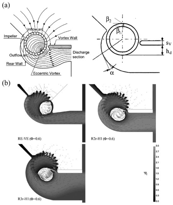
Figure 1. (a) Representation of the contributing parameters and (b) contour plots for the total pressure field (adapted from [10]).
Ozer and Kumlutas [11] conducted a study to examine the flow effects of an embedded Cross-Flow Fan (CFF) within a Split Air Conditioner (SAC). Their research involved a parametric study aimed at evaluating the impact of specific parameters on the defined objective. As illustrated in Figure 2a, the parametric prototype consists of a base and parametric components. For a clearer perspective, the schematic diagram of all the parameters under consideration is presented in Figure 2b, encompassing elements such as volute design, tongue angle, vortex wall angle, and vortex wall distance. To assess the impact of these design parameters on flow structures, the researchers employed Stereo Particle Image Velocimetry (SPIV). Their findings revealed the significance of each parameter. Notably, the vortex wall angle was found to have an approximate 12% effect, while the volute curvature exerted a 32% influence on the flow rate.
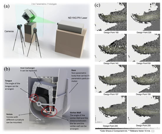
Figure 2. Representation of the (a) experimental setup, (b) parametric prototype of SAC indoor unit, and (c) two-dimensional component flow structure (adapted from [11]).
Despite the various applications of Cross-Flow Fans (CFFs), recent research has been increasingly focused on their potential implementation in Power-Lift Regional Aircraft, as exemplified by the work of Gologan and colleagues [12]. Indeed, CFFs have shown promising potential for enhancing the lift coefficient, which is a critical factor in aircraft design. A conceptual representation of a regional aircraft featuring a CFF for a powered lift system can be seen in Figure 3a. This design concept illustrates the idea of integrating CFFs in over-wing mounted engines. Figure 3b visually demonstrates how this integration leads to an increase in aerodynamic lift by reducing static pressure on the upper side of the airfoil. Furthermore, Figure 3c provides an overview of the flow field associated with the CFF, encompassing the fan intake and outlet. Notably, the maximum speed recorded was 200 m/s, indicating flow separation in the inlet duct. The observed compatibility of the inlet lip radius with the desired outcome is a noteworthy finding. The authors of this study assert that various design parameters, including fan blades, ducts, and airfoil shape, play a pivotal role in optimizing such designs. This research contributes valuable insights into the potential application of CFFs in enhancing lift coefficients for Power-Lift Regional Aircraft.
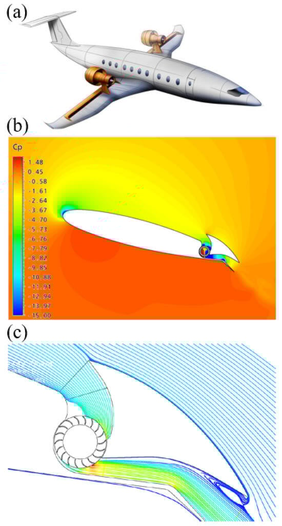
Figure 3. Representation of (a) an artist’s view of a regional aircraft with CFF-powered lift system, (b) pressure coefficient for propulsive airfoil, and (c) streamlines for the CFF flow (adapted from [12]).
In response to the insights gleaned from the studies mentioned earlier, a cohort of dedicated researchers has undertaken the ambitious task of conducting a multi-objective optimization, with a particular focus on enhancing the performance of Cross-Flow Fans (CFFs). As previously explored, Toffolo and their team were acutely aware of the intricacies inherent in the flow field surrounding CFFs. Their research was intentionally oriented toward the intricate process of designing these fans, with a primary goal of delving into the intricate relationships that exist between various design parameters and the multitude of characteristics that define CFF performance. Their investigation, characterized by its depth and thoroughness, ventured into the repercussions of altering both the casing and impeller on the static pressure coefficient. This multifaceted exploration yielded a diverse array of outcomes, highlighting the inherently complex nature of CFF design and performance. It is evident from these variations that there is a pressing need for a comprehensive and systematic inquiry into the intricate and multifaceted influence of design parameters on the performance of CFFs. This quest for optimization is poised to unlock a deeper understanding of these fan systems, ultimately leading to more efficient and effective applications across various industries.
2. Aerodynamic Characteristics and Performance of CFFs
In the pursuit of enhanced energy efficiency, a pivotal criterion across diverse applications, organizations worldwide are diligently engaged in efforts to control and optimize their energy consumption. This proactive approach is geared towards augmenting the efficiency of production processes, aligning with the broader goal of sustainable energy usage. Within this landscape, scientists and researchers have embarked on an intensive exploration of Cross-Flow Fans (CFFs) through meticulous experimental and numerical analyses. Among the myriad challenges encountered by scientists delving into CFF studies, one of the focal points has been the comprehensive analysis of performance. This endeavor involves a rigorous evaluation of the aerodynamic characteristics of CFFs, encompassing intricate aspects such as flow characteristics and in situ visualization, as well as the diverse flow patterns inherent in this type of fan. To address these challenges, numerous studies have been undertaken, each contributing valuable insights into the behavior of CFFs under varying conditions. One noteworthy area of exploration has been the examination of flow characteristics concerning different parameters, a topic thoroughly investigated in seminal works such as [13].
2.1. Flow Characteristics
In CFFs, the working fluid undergoes two passes through the impeller, eliminating any distinction between inlet and exit angles. This characteristic leads to CFFs having higher dynamic pressure and greater circumferential velocity. In fact, the flow fields within CFFs exhibit various vortices, including the eccentric vortex and the free vortex.
Kim et al. [14] involved a comprehensive assessment of the flow dynamics and performance of Cross-Flow Fans (CFFs). To delve into this analysis, they considered a range of critical design parameters, including the stabilizer position, setting angle, impeller exit angle, and rear guider shapes. A dedicated design program was developed to calculate the pertinent parameters and facilitate this investigation. Their approach encompassed both numerical simulations and experimental procedures. By comparing the results derived from their custom-designed program, they aimed to obtain a thorough understanding of CFF behavior. The numerical aspect of their analysis involved the discretization of governing equations through the Finite Volume Method (FVM), allowing them to compute solutions for flow variables. To identify an optimal geometry, Kim et al. applied the k-𝜖
turbulence model and utilized experimental apparatus. The integration of numerical and experimental data empowered them to refine the design and enhance the performance of CFFs, a valuable contribution to the field of fan technology.
Funaki et al. [15] focused on investigating the impact of aspect ratio and Reynolds number on short-axis Cross-Flow Fans (CFFs). In contrast to the study conducted by Kim et al., the authors adopted a Particle Image Velocimetry (PIV) technique to precisely measure flow velocities within the CFF. Notably, their experimental setup did not incorporate casings, and their examination centered on two distinct impeller types: forward-chambered blades and radial-flat blades. A significant outcome of their study was the ability to categorize the generated flow into three distinct modes. As a result of this classification, Funaki et al. created flow-regime maps specifically tailored to the impellers they employed. One of the most noteworthy aspects of their research pertained to the definition of an outflow rate from the impeller, which they derived from the PIV results. Their conclusion was particularly intriguing, as it revealed that the outflow rate coefficient remained independent of both the Reynolds number and aspect ratio. This finding holds particular relevance for the understanding and design of short-axis CFFs, offering valuable insights into their operational characteristics.
Tsai et al. [16] analyzed the flow patterns of CFF with three different rotor-screw angles (RSA). Their observation methods and findings are summarized in Figure 4, which includes (a–c) the visualization of the 3D axial flow patterns and (d) cross-sectional observations at different speeds for RSA-0. Based on the results obtained from their proposed flow visualization setup, it is evident that each angle has a distinct impact on the pressure levels and noise generation.
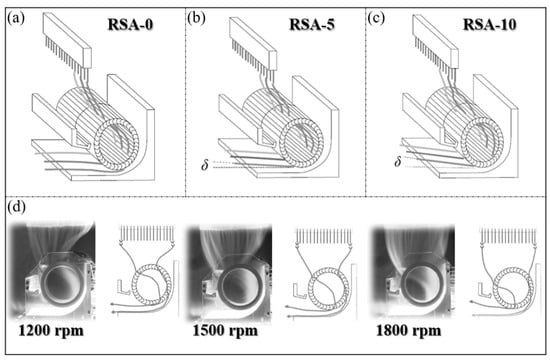
Figure 4. (a–c): Visualization of the 3D axial flow pattern and (d): cross-section observation at various speed for RSA-0 (adapted from [16]).
In addition to the various applications of CFFs, other research endeavors have sought to assess the aerodynamic and aeroacoustic characteristics of these fans. Kumlutas et al. [17] delved into both the fluid dynamics and heat transfer aspects of a Split Air Conditioner (SAC) while considering the integration of a CFF within this specific application. They placed particular emphasis on comprehending the intricate flow patterns that manifest within CFFs, and, as a result, they introduced a comprehensive 3D model to analyze the airflow and heat transfer within the SAC unit. To be more precise, they proposed a thin-section model for simulating the indoor unit of the SAC. It is worth noting that this innovative approach serves as a general framework, which is ultimately destined for application in a real-world scenario to verify its validity. Consequently, they conducted experimental tests to validate their proposed model. Furthermore, they sought to validate their model through experimental procedures involving heat transfer measurements and Stereo Particle Image Velocimetry (SPIV). Given that the internal structure of the SAC unit includes the CFF, rear wall, and vortex wall, the airflow within the unit was modeled using a 2D approach, employing nodes for implementing the Finite Volume Method (FVM). The 3D numerical model of the SAC indoor unit, along with mesh details, is presented in Figure 5.
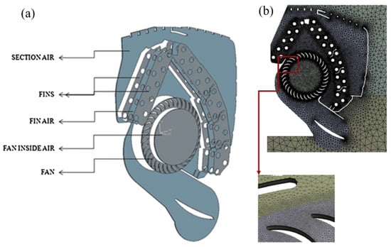
Figure 5. (a) Regions of the 3D model and (b) mesh detail of the numerical model (adapted from [17]).
In the numerical analysis of fluid flow, after implementing the boundary conditions and setting the specified velocity at 1200 rpm, the flow conditions were visualized using streamlines (refer to Figure 6). As shown, the airflow originates from the upper exterior region and moves towards the suction holes. This results in the formation of a jet flow, driven by the substantial pressure differential between the conditioned and ambient air.
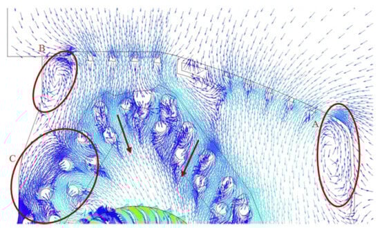
Figure 6. Vector field at the inlet zone of the air conditioner representing: (A) the flow separation through the pipe surfaces, (B) the vortexes behind the pipes, and (C) reverse flow regions at the corners of the air conditioner (adapted from [17]).
Overall, it has been shown that there is a good agreement between the numerical and experimental approaches. Consequently, the thin-section model is an acceptable assumption through evaluating the CFFs’ performance. A capacity difference of 0.26% between the test room data and the developed model was obtained, as mentioned by the authors.
The influence of various design parameters such as impeller exit angles, stabilizer position, and setting angle on the performance and flow characteristic of CFF has been investigated using a numerical approach [14]. The standard k-𝜖
turbulence model has been applied to simulate the turbulence behavior. Considering the experimental validation of the proposed approach, an optimum design has been obtained following the obtained experimental and numerical results.
2.2. Flow Regions
Cross-Flow Fans (CFFs) offer distinctive advantages in various applications due to their specific design. Nevertheless, one of their most significant drawbacks is their relatively low efficiency, which is why research and efforts to enhance this type of fan are ongoing. As the utilization of CFFs varies from Split Air Conditioners to aircraft, the need for a standardized design with specific parameters becomes apparent. Therefore, it is essential to recognize the distinct characteristics of these fans in their various applications.
To acknowledge the mentioned issues, the basic aerodynamics and energy transfer processes should be taken into account. One can mention the flow and its characteristics within the impeller. In fact, the flow field in a CFF is two-dimensional, which transfers from the blade row, passes within the interior of the impeller, and then passes radially through the blade row. The most important feature is that the characterization of flow can take place by the construction of the eccentric vortex placed parallel to the rotor axis. Accordingly, researchers have tried to perform experimental work on this part [18]. It has been shown that even with the casing wall, the mentioned eccentric vortex would still exist. To realize more specifically the flow’s characteristics, other works have been developed numerically. Bushnell et al. have assumed the flow of a fan could be divided into three zones. The most important feature of this approach is that the flow region boundaries rely on the prediction of the flow, which itself is influenced by the design parameters based on the findings of other related works [19][20][21].
There are three flow regions in CFFs, as mentioned previously. These regions are schematically illustrated in Figure 7. Dang and Bushnell [22] have comprehensively discussed these flow regions. They are named A, B, and C. Region A corresponds to the inlet flow and includes most of the air that enters the fan. The flow in region A consists of two stages: flow passage through the suction arc blading and flow passage through the discharge arc. In this zone, the effect of the vortex could be included along with the two stages augmenting the pressure coefficient. Region B refers to the zone that is the important part of the flow passage in CFFs, and its role is not effective on the fan’s performance. Region C is exactly the eccentric vortex. The most important feature of this zone is that there is a re-circulating of flow, and, thus, there might be energy dissipation that affects region A.
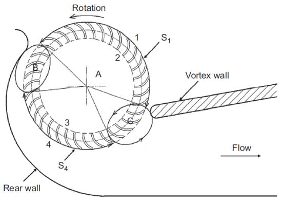
Figure 7. Definition of the flow regions for mean-line analysis (adapted from [22]).
From the above-mentioned explanations, it seems that regions B and C do not play an important role in the flow characterization of CFFs. However, their role is inevitable and should be considered for the flow field evaluation accordingly.
Dang and Bushnell have characterized the energy transfer and flow characterization in regions A, B, and C. As the most critical region in CFFs refers to the flow in region A, it is important first to consider this issue and then apply the findings as the boundary conditions for regions B and C. They have considered the velocity diagram to correlate them to the first and second stages for further investigations. Efforts have been taken into consideration to obtain the pressure coefficient as an important criterion in the performance analysis of CFFs.
2.3. Flow-Field Pattern
In 1891, the structure of the flow field was patented. After a few years, several visualization studies were performed through an eccentric vortex within the impeller, and it was found that the vortex is capable of acting as an aerodynamic seal for controlling the re-circulation of flow from discharge. In the work of Eck et al., they proposed a small rear wall along with a thick vortex wall, taking into account a decrease in the value of the radial clearance in the rotation direction. Another work has considered the pressure coefficient as an important criterion representing the role of the vortex on the flow-field pattern [18].
In addition to the described works, several efforts have been taken into account to develop numerical approaches regarding the prediction of fan performance. The most important works are summarized as follows:
Accordingly, there are other studies that have worked on the flow field experimentally. Murata and Nishihara have worked on the flow field and its relation with the characteristic curve by which the casing shapes have been thoroughly investigated [5]. They have considered the different casing shapes to evaluate their effect on the flow field in various geometric parameters. Furthermore, several impeller blade profiles, such as radial and circular, have been tested, and the author showed that the eccentric vortex varies for different profiles [26].
Based on the geometry of the designed CFFs and also the operating conditions, there might be secondary vortices in the inlet and outlet zones. As shown in Figure 8, CFFs consist of a broad cylindrical rotor by which air passage takes place through the blade two times. In fact, the airflow controlled by a large vortex on both the inside and outside of the impeller is a function of the vortex’s size and intensity that is affected by the geometrical parameters of the casing as well as the operation point [27][28].
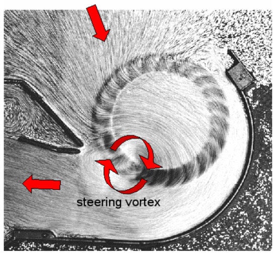
Figure 8. Flow field in CFFs (adapted from [28]).
Due to the complexity of the airflow and its structure, it is crucial to perform several experimental tests. On the other hand, as the design techniques are not applicable in CFFs with acceptable results, implementing numerical techniques is inevitable. The objective is to simulate the complex flow in CFFs and avoid a large number of experiments in the design and development procedures. To accomplish this, Computational Fluid Dynamics (CFD) calculation is an approach for simulation of the flow field and other related characteristics of the CFFs [29]. It is worth mentioning that experimental techniques, such as Particle Image Velocimetry (PIV), are normally used for measurement of the characteristics and performance of the CFFs as a manner of experimental validation of the implemented numerical simulations [30][31].
In CFFs, the most important part that has an effect on the flow field is the inner side of the impeller. To be able to perform the related investigation, it is required to determine the variation in pressure coefficient, volume flow coefficient, efficiency, and velocity. Mostly, 2D CFD calculations have been implemented to evaluate the flow in different applications of CFFs. In fact, the development of numerical approaches can create a platform for the complete calculation of the inner flow of the CFFs by using CFD software based on different methods, such as the Finite Volume Method.
Gebrehiwot et al. [32] have investigated the impact of outlet on flow patterns using CFD calculations for different designs, including the outlet duct shapes. Furthermore, they have evaluated the effect of geometry variation and the static pressure variation in the eccentric vortex center in order to be able to obtain a balance toward the airflow division within the two outlet ducts. Based on their experimental tests, the performance of the rotors was shown to be similar and caused an increase in the total pressure over the rotors.
Shih et al. [33] studied the effect of internal flow in a CFF and its effect on the performance of these types of fans. They have focused on the eccentric vortex and found that three factors cover this parameter: vortex wall or tongue, rear wall, and rotor orientation. The point is that when there is a rotation of the rotor, the formation of the vortex is inside the center of the rotor with a symmetrical flow field. However, in the presence of the vortex wall near the rotor, the vortex tends to move toward it and produce an eccentric vortex. The center of this vortex is inside the rotor, affecting the transient flow and dividing the internal flow. Accordingly, there have been several CFD calculations toward the prediction of internal flow [29][34][35]. These calculations help perform better design and optimization toward improving the performance of the CFFs. To come back to the work of Gebrehiwot et al., it is worth mentioning that different outlet configurations have been implemented to predict the impeller performance along with a balance over the existing flow toward the parallel outlets.
In the first case, the static pressure and the total pressure have been calculated. Changing the static and dynamic pressures, the total pressure over the rotor has been increased, which is highly related to the mass flow. Additionally, a value of 𝜓=1
has shown that the movement of the vortex wall results in augmenting the rotor outlet area. In the second case, the balance over the distributed flow of the test cases shows a variation through the outlets of the designed CFFs with an average variation of 45%, which should be taken into account as an important step toward optimization purposes.
Wan et al. [36] evaluated the internal flow with the pressure of the air duct, and they found that the generated flow was not uniform. They have stated that the definition of eccentric vortex results in loss of airflow, and thus, they have proposed various designs and performed numerical simulations. Their results showed that the flow rate is small and the velocity distribution is uniform. In another work, the effects of tongue shape and impeller geometry on the flow field of CFFs have been evaluated [37]. Different impellers have been designed by considering various blade angles and radius ratios; it was found that each design has its own effect on the total pressure and efficiency. The smaller the vortex size, the higher the performance, as stated based on the performed design for the rotors.
Casarsa and Giannattasio [38] have also mentioned that the eccentric vortex has a crucial role in the axial fluid mechanism to characterize the 3D flow structure that exists in CFFs. In fact, they have implemented high-resolution PIV measurements to evaluate the flow field of the fans. These measurements have shown that there is a flow re-circulation near the casing wall, and this issue should be taken into account in the design approaches of the CFFs.
Li et al. [39] have also investigated the performance of embedded CFF in the window purifying ventilator by determining the flow pattern and internal flow resistance. They have used the sliding mesh technique to consider the rotation of the impellers. In fact, a stationary and a rotational zone was defined by which the vortex wall, rear wall, and casing were in the stationary zone, and the impellers were in the rotational zone. Efforts have been made to apply the standard, RNG, and k-𝜖
models to simulate and validate with experimental data to find the best model for the performed design and, consequently, for optimization purposes. They have concluded that the role of the vortex wall is inevitable and highly affects the performance of the CFFs. In addition, they have proposed consideration of the proposed design within the ventilator with an acceptable flow coefficient.
More recently, Himeur et al. [40] have presented a novel methodology in order to predict the performance of the CFFs by focusing on its correlation with the internal field by applying a multidisciplinary approach. Figure 9 indicates the applied CFD meshing as well as the predicted efficiency for the applied CFFs’ geometry. When applying CFD simulation as well as an optimization algorithm combined with the internal flow field, there was good agreement with the experimental data, as reported by the authors.
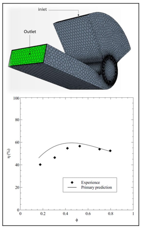
Figure 9. CFD meshing of the internal flow and efficiency prediction of the applied CFFs (adapted from [40]).
References
- Lazzaretto, A. A criterion to define cross-flow fan design parameters. J. Fluids Eng. 2003, 125, 680–683.
- Eck, B. Fans–Design and Operation of Centrifugal, Axial-Flow and Cross Fans; Pergamon Press: Oxford, UK, 1973.
- Tanaka, S.; Murata, S. Scale Effects in Cross Flow Fans: Effects of Fan Dimensions on Flow Details and the Universal Representation of Performances. JSME Int. J. Ser. B Fluids Therm. Eng. 1995, 38, 388–397.
- Tanaka, S.; Murata, S. Scale Effects in Cross-Flow Fans: Effects of Fan Dimensions on Performance Curves. JSME Int. J. Ser. B Fluids Therm. Eng. 1994, 37, 844–852.
- Murata, S.; Nishihara, K. An experimental study of cross flow fan: 1st report, effects of housing geometry on the fan performance. Bull. JSME 1976, 19, 314–321.
- Tanaka, S. Scale effects in cross-flow fan. Jsme Int. 1995, 38, 388–397.
- Matsuki, K. Experimental study of internal flow of a room air conditioner incorporating a cross flow fan. ASHRAE Trans. 1988, 94, 350–364.
- Kim, J.W.; Ahn, E.Y.; Oh, H.W. Performance prediction of cross-flow fans using mean streamline analysis. Int. J. Rotating Mach. 2005, 2005, 112–116.
- Wu, C.; Liu, D.; Pan, J. A study of the aerodynamic and acoustic performance of an indoor unit of a DC-inverter split air-conditioner. Appl. Acoust. 2012, 73, 415–422.
- Toffolo, A. On the theoretical link between design parameters and performance in cross-flow fans: A numerical and experimental study. Comput. Fluids 2005, 34, 49–66.
- Özer, Ö.; Kumlutaş, D. Experimental investigation on cross flow fan’s casing parameters inside of a split air conditioner indoor unit by Stereo Particle Image Velocimetry. Appl. Therm. Eng. 2017, 124, 1233–1246.
- Gologan, C.; Mores, S.; Steiner, H.; Seitz, A. Potential of the cross-flow fan for powered-lift regional aircraft applications. In Proceedings of the 9th AIAA Aviation Technology, Integration, and Operations Conference (ATIO) and Aircraft Noise and Emissions Reduction Symposium (ANERS), Hilton Head Island, SC, USA, 21–23 September 2009; p. 7098.
- Coester, R. Theoretische und Experimentelle Untersuchungen an Querstromgebläsen. Ph.D. Thesis, ETH Zurich, Zurich, Switzerland, 1959.
- Kim, Y.J. Flow Characteristics in a Cross-Flow Fan with Various Design Parameters. In Fluid Machinery and Fluid Mechanics; Springer: Berlin/Heidelberg, Germany, 2009; pp. 255–261.
- Funaki, J.; Kimata, N.; Hisada, M.; Hirata, K. Aspect-ratio and Reynolds-number effects on short-span cross-flow impellers without casings. JSME Int. J. Ser. B Fluids Therm. Eng. 2006, 49, 1197–1205.
- Tsai, G.L.; Tu, T.H.; Li, T.C.; Wang, K.H. Flow style investigation and noise reduction of a cross-flow fan with varied rotor-skew-angle rotor. JSME Int. J. Ser. B Fluids Therm. Eng. 2006, 49, 695–704.
- Kumlutaş, D.; Karadeniz, Z.H.; Kuru, F. Investigation of flow and heat transfer for a split air conditioner indoor unit. Appl. Therm. Eng. 2013, 51, 262–272.
- Porter, A.; Markland, E. A study of the cross flow fan. J. Mech. Eng. Sci. 1970, 12, 421–431.
- Noel, J.; Farall, M.; Casarsa, L. Aero-acoustics in a tangential blower: Validation of the CFD flow distribution using advanced PIV techniques. Int. J. Multiphysics 2007, 1, 377–392.
- Hirata, K.; IIDA, Y.; TAKUSHIMA, A.; FUNAKI, J. Instantaneous pressure measurement on a rotating blade of a cross-flow impeller. J. Environ. Eng. 2008, 3, 261–271.
- Moore, A. The tangential fan-analysis and design. In Proceedings of the Conference on Fan Technology and Practice, London, UK, 18–19 April 1972; pp. 66–82.
- Dang, T.Q.; Bushnell, P.R. Aerodynamics of cross-flow fans and their application to aircraft propulsion and flow control. Prog. Aerosp. Sci. 2009, 45, 1–29.
- Ilberg, H.; Sadeh, W. Flow theory and performance of tangential fans. Proc. Inst. Mech. Eng. 1965, 180, 481–496.
- Tramposch, H. Cross-Flow Fan; ASME Paper no. 64-WA/FE-25; ASME: New York, NY, USA, 1964.
- Ikegami, H. A Study of Cross Flow Fan (I. A Theoretical Analysis). Technol. Rep. Osaka Univ. 1966, 16, 556–578.
- Yamafuji, K. Studies on the flow of cross-flow impellers: 1st report, experimental study. Bull. JSME 1975, 18, 1018–1025.
- Eck, B. Ventilatoren; Springer: Berlin/Heidelberg, Germany, 1972.
- Gabi, M.; Klemm, T. Numerical and experimental investigations of cross-flow fans. J. Comput. Appl. Mech. 2004, 5, 251–261.
- Dornstetter, S. Numerische und exper Imentelle Untersuchungen an Querstromventilatoren. Ph.D. Thesis, Universität Karlsruhe, Karlsruhe, Germany, 2002.
- Gabi, M.; Dornstetter, S.; Klemm, T. Investigation of the flow field in crossflow fans by particle imaging velocimetry. In Proceedings of the 10th International Symposium on Flow Visualization, Kyoto, Japan, 26–29 August 2002.
- Raffel, M.; Willert, C.E.; Scarano, F.; Kähler, C.J.; Wereley, S.T.; Kompenhans, J. Particle Image Velocimetry: A Practical Guide; Springer: Berlin/Heidelberg, Germany, 1998; Volume 2.
- Gebrehiwot, M.G.; De Baerdemaeker, J.; Baelmans, M. Numerical analysis of a cross-flow fan with two outlets. HEFAT 2007, 2007.
- Shih, Y.C.; Hou, H.C.; Chiang, H. Numerical Study of the Similarity Law for the Cross-Flow Fan of a Split-Type Air Conditioner. ASHRAE Trans. 2004, 110, 378–388.
- Moon, Y.J.; Cho, Y.; Nam, H.S. Computation of unsteady viscous flow and aeroacoustic noise of cross flow fans. Comput. Fluids 2003, 32, 995–1015.
- Fukano, T.; Chen, C.; Hara, Y. A Numerical Analysis of Flow in a Cross-Flow Fan; ASME: New York, NY, USA, 1995; Volume 227, pp. 53–58.
- Wan, Z.M.; Zheng, Z.Y.; Wan, J.H.; Liu, J.; Huang, C.Q.; Wang, L. Numerical Analysis and Optimal Design Investigation on Air Duct of Tent Air-conditioner. Adv. Mater. Res. 2013, 644, 216–220.
- Govardhan, M.; Venkateswarlu, G. Effect of impeller geometry and tongue shape on the flow field of cross flow fans. J. Therm. Sci. 2003, 12, 118–125.
- Casarsa, L.; Giannattasio, P. Experimental study of the three-dimensional flow field in cross-flow fans. Exp. Therm. Fluid Sci. 2011, 35, 948–959.
- Li, J.; Hou, Y.; Liu, J.; Wang, Z.; Li, F. Window purifying ventilator using a cross-flow fan: Simulation and optimization. Build. Simul. 2016, 9, 481–488.
- Himeur, R.M.; Khelladi, S.; Ait Chikh, M.A.; Vanaei, H.R.; Belaidi, I.; Bakir, F. Towards an Accurate Aerodynamic Performance Analysis Methodology of Cross-Flow Fans. Energies 2022, 15, 5134.
More
Information
Subjects:
Engineering, Industrial
Contributors
MDPI registered users' name will be linked to their SciProfiles pages. To register with us, please refer to https://encyclopedia.pub/register
:
View Times:
2.2K
Revisions:
4 times
(View History)
Update Date:
19 Dec 2023
Table of Contents


Notice
You are not a member of the advisory board for this topic. If you want to update advisory board member profile, please contact office@encyclopedia.pub.
OK
Confirm
Only members of the Encyclopedia advisory board for this topic are allowed to note entries. Would you like to become an advisory board member of the Encyclopedia?
Yes
No
${ textCharacter }/${ maxCharacter }
Submit
Cancel
Back
Comments
${ item }
|
${ item.createdUser.fullName }
${ item.createdAt }
${ item.vote }
${ item.reply }
Delete
${ reply.createdUser.fullName }
${ reply.createdAt }
${ reply.vote }
Delete
There is no reply to this comment~
${ item.replyTextCharacter }/${ item.replyMaxCharacter }
Submit
Cancel
More
No more~
There is no comment~
${ textCharacter }/${ maxCharacter }
Submit
Cancel
${ selectedItem.replyTextCharacter }/${ selectedItem.replyMaxCharacter }
Submit
Cancel
Confirm
Are you sure to Delete?
Yes
No