Your browser does not fully support modern features. Please upgrade for a smoother experience.
Submitted Successfully!
 +1 credit
Thank you for your contribution! You can also upload a video entry or images related to this topic.
For video creation, please contact our Academic Video Service.
| Version | Summary | Created by | Modification | Content Size | Created at | Operation |
|---|---|---|---|---|---|---|
| 1 | Jose Manuel Costa | -- | 3267 | 2023-12-11 11:52:55 | | | |
| 2 | Rita Xu | Meta information modification | 3267 | 2023-12-12 02:27:37 | | |
Video Upload Options
We provide professional Academic Video Service to translate complex research into visually appealing presentations. Would you like to try it?
Cite
If you have any further questions, please contact Encyclopedia Editorial Office.
Costa, J.M.; Sequeiros, E.W.; Vieira, M.F. Fused Filament Fabrication for Metallic Materials. Encyclopedia. Available online: https://encyclopedia.pub/entry/52579 (accessed on 26 July 2026).
Costa JM, Sequeiros EW, Vieira MF. Fused Filament Fabrication for Metallic Materials. Encyclopedia. Available at: https://encyclopedia.pub/entry/52579. Accessed July 26, 2026.
Costa, Jose M., Elsa W. Sequeiros, Manuel F. Vieira. "Fused Filament Fabrication for Metallic Materials" Encyclopedia, https://encyclopedia.pub/entry/52579 (accessed July 26, 2026).
Costa, J.M., Sequeiros, E.W., & Vieira, M.F. (2023, December 11). Fused Filament Fabrication for Metallic Materials. In Encyclopedia. https://encyclopedia.pub/entry/52579
Costa, Jose M., et al. "Fused Filament Fabrication for Metallic Materials." Encyclopedia. Web. 11 December, 2023.
Copy Citation
Fused filament fabrication (FFF) is an extrusion-based additive manufacturing (AM) technology mostly used to produce thermoplastic parts. FFF for metallic parts can be divided into five steps: (1) raw material selection and feedstock mixture (including palletization), (2) filament production (extrusion), (3) production of AM components using the filament extrusion process, (4) debinding, and (5) sintering.
additive manufacturing
solid-state processes
material extrusion
fused filament fabrication
1. Introduction
Additive manufacturing (AM) processes, commonly called 3D printing, are receiving the attention of several industries. These processes allow layer-by-layer construction of complex and customized shaped parts from engineering materials directly from design, without using expensive tooling [1][2][3][4][5]. To accomplish the AM potential, continued research and development on processes and equipment are essential to enable full manufacturing readiness and understanding of the materials [3][4]. AM processes in general, from laser to solid-state processes, can create complex shapes and components from various materials, including plastics, metals, ceramics, and composites, like metal matrix composites (MMC), functionally graded materials (FGM), high entropy alloys (HEA), and others [6][7][8][9][10]. The beam (laser or electron) powder processes are the most used technologies in metal AM. The pertinence and capabilities of this type of process are widely demonstrated and recognized. Thus, this technology has emerged as challenging, since layer-by-layer manufacturing with a heat source leads to columnar grain formation due to the directionality of heat extraction. This microstructure has characteristics dissimilar from those of traditional processes; it usually reveals an anisotropy that degrades mechanical strength in Z-axis directions (or with enhanced strength in the XY-axis), resulting in components that can have unpredictable mechanical behavior, incompatible with parts that require stringent properties [11][12][13][14]. The metal AM processes require high-end and digital technology, like hardware, software, and procedures. They are an intrinsic part of a new industrial paradigm to increase efficiency and productivity by ensuring sustainability and the improvement of the circular economy [3][9][15][16][17].
Fused filament fabrication (FFF) is a material extrusion (MEX) process where material under a filament form is selectively dispensed through a nozzle [18], and it is grouped inside the additive manufacturing (AM) solid-state processes [2][19], where applying debinding and sintering is required. FFF uses a continuous feed of material or mixing of materials, a mixture of metal powders with polymeric binder systems [11], which are melted and deposited layer-by-layer to build an object [20][21][22][23]. FFF is known for its cost-effectiveness and versatility, and is popular for many applications in the automotive, aerospace, and healthcare industries, as well as consumer and markets in general [11][24][25][26][27], since it allows the user to design, create, develop, and produce almost any product with design freedom, flexibility, and versatility when compared to traditional manufacturing [1][3][4][28].
One of the mandatory requirements to achieve an effective layer joining in AM, independently of the selected technology, is to have a proper combination of the feedstock (or raw) material and good energy delivery [29]. As mentioned before, in the FFF process, a filament composed of a binder system mixed with metal powder particles, which is fed through a nozzle, is used to produce components according to the 3D model, and layered according to it; in the end, a green part is achieved [26][27][30]. Afterward, the steps of debinding and sintering treatments are required to create fully metallic parts. The debinding is a critical stage in the production of FFF parts, in which the polymeric binder systems that have been instrumental in holding the powders together are carefully and methodically removed, obtaining the densified brown parts. To attain components with desired densities and structural integrity, the brown parts are sintered through controlled heating, resulting in solid and dense structure components [11][31][32][33][34].
2. The FFF Process for Metallic Materials
FFF has gained recognition as a potential substitute for laser or electron beam processes, mainly due to the easy process and easy-to-use equipment, and smaller overall costs and reduced initial investment, creating new opportunities for advancing metal AM technology [1][5][6][35][36]. The flexibility and widespread accessibility of FFF highlight its utility in various domains such as engineering, design, research, and art, allowing for the production of a diverse range of objects, including prototypes, functional components, models, and intricate artistic sculptures [5][27][37].
FFF for metallic parts can be divided into five steps: (1) raw material selection and feedstock mixture (including palletization), (2) filament production (extrusion), (3) production of AM components using the filament extrusion process, (4) debinding, and (5) sintering. Figure 1 represents the schematics for these five steps of the FFF process.
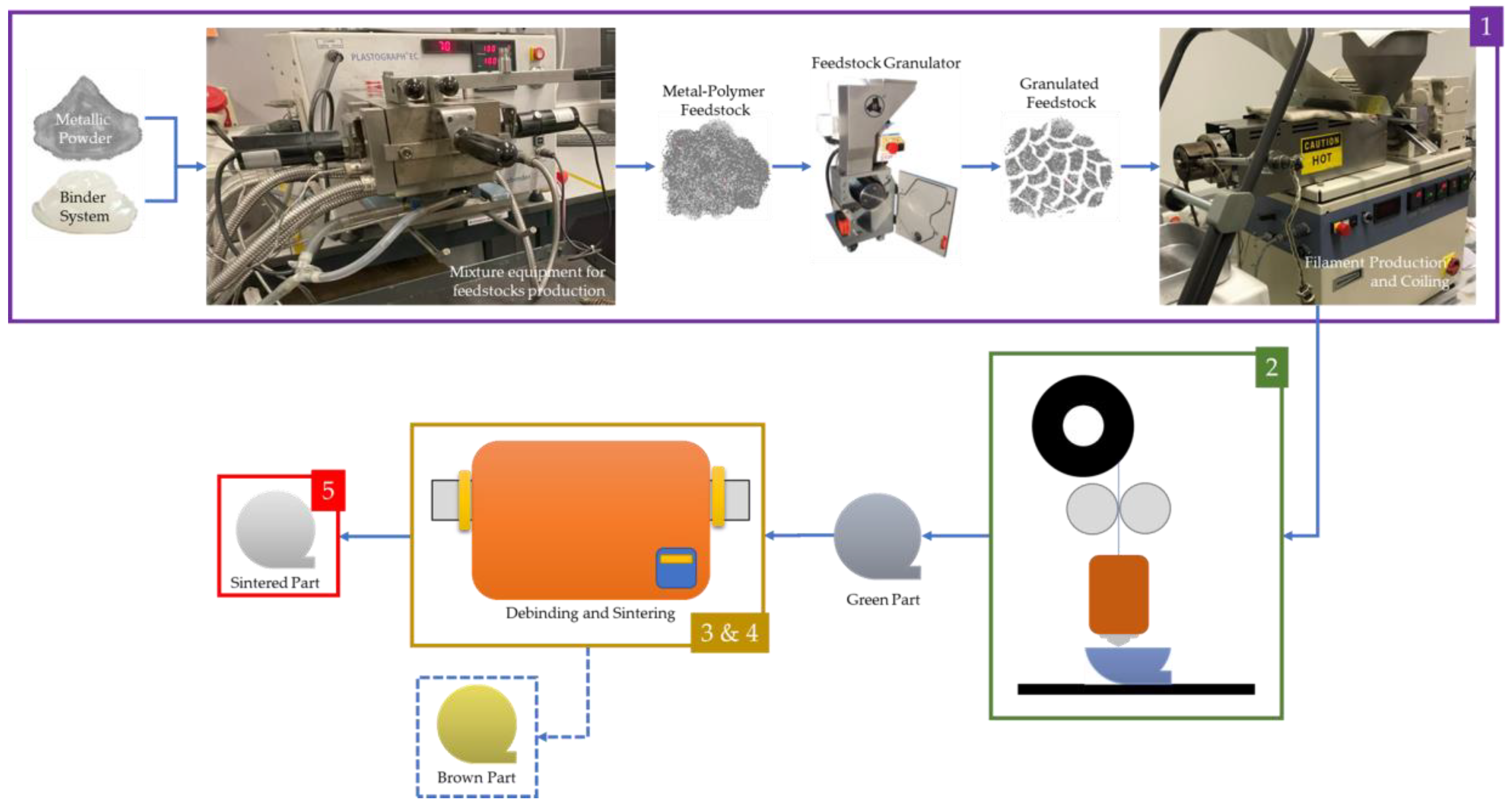
Figure 1. Schematics of FFF for metallic filament feedstock: (1) filament production (including material selection and mixing); (2) production of AM component (green part) using the filament extrusion process; (3) debinding (brown part); (4) sintering, and; (5) sintered part.
The production of filaments for metal-based AM is a critical step in the process. It includes material selection and mixture and the extrusion process into the form of the filament. The selection of appropriate materials, including metallic powders, binders, and additives, is essential to producing successful parts. The filaments utilized in metal-based AM result from feedstock extrusion, combining metallic powders and a polymer binder system in specific proportions, typically with 60% metallic powders and 40% polymeric materials. The objective of this mixture, similar to metal hot embossing and metal injection molding, is to distribute the metal powder evenly throughout the binder, preventing internal porosity and agglomeration and resulting in a homogeneous biphasic mixture [3][6][26][38][39][40]. The powder characteristics and properties significantly impact the filaments’ rheological behavior during their manufacture and the FFF process. Ideally, filament characterization should include results such as powder particle size distribution, powders morphology, density, specific surface area, inter-particle interaction, thermo-gravimetric analysis, and differential scanning calorimetry [3][40][41][42][43]. Filament production is a complex operation where the selected process parameters must suit the specific compound and extrusion system used and preliminary optimized for each filament. The filament is usually extruded into a spool. It must be pre-optimized to ensure the blend is homogeneous and has a consistent shape and diameter (usually 1.75 mm or 2.85 mm diameter). A suitable and practical FFF process requires the combination of an appropriate feedstock and extrusion, which enables a stable and effective (and profitable) process [3][27]. The core features for the FFF process in metallic materials are the correct powder load and melt of the filament, adequate pressure to push the molten material through the nozzle to enable a controlled extrusion in the correct coordinate (defined in slicing), and proper bonding of the material extruded, which all create a solid structure [5][26][35][44].
There are other processes similar to FFF, which avoid the production of filaments that are being developed. Fused granular fabrication (FGF), where it is possible to use pellets (or granulates) as feedstock [20][21][45][46][47] instead of filament, offers several benefits, including a broader range of material options, lower costs, and reduced waste production. However, using pellets also presents challenges, such as higher temperatures required to melt the pellets, more force needed to push them through the nozzle, and limited availability of specific materials [21][45]. Direct ink writing processes (also known as material jetting (MJT)), where an ink with nanometric metal powder is used as feedstock, where the droplets of the metallic ink are selectively deposited using piezo printing heads. Subsequent curing, often through processes like sintering, solidifies the metal particles, layer-by-layer, to form the desired 3D object. This technology enables the creation of intricate and customized metal components with a high level of precision, making it suitable for various applications, including prototyping and functional part production [48][49][50][51][52][53][54]. However, parts produced with this technology have high porosity and insufficient cohesion between layers [54]. Binder jetting (BJT) builds components by selectively depositing a liquid binder (bonding agent) onto layers of metallic powder to join them. This process operates at ambient temperature, which mitigates thermally induced defects (common in other heat-dependent AM methods), where the surrounding metal powder acts as both a structural component and temporary support, eliminating the need for additional supports and minimizing waste. The process involves depositing a fine layer of metallic powder onto a build platform, followed by the controlled application of binder through an inkjet printhead, resulting in a uniform distribution achieved through capillary pressure and gravitational forces [55][56][57]. Parts produced by binder jetting also have internal porosity, which affects mechanical behavior; in particular, fatigue and fracture resistance can have a very negative impact from this porosity [57][58].
In the realm of AM, particularly in FFF (and similar processes), a well-structured workflow is crucial for producing high-quality FFF components, involving several key stages before production [3][4][5], including design (CAD), optimization (design for AM–DfAM), simulation, and production preparation (using slicing software), as seen in Figure 2.
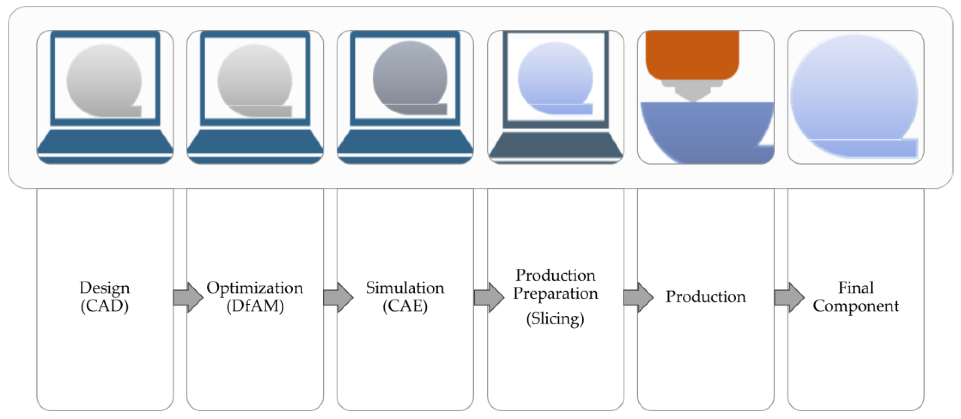
Figure 2. FFF workflow.
In the FFF process, common to various AM technologies, the initial phase involves designing components using CAD software. Design for AM plays an important role since it explores the unique capabilities and constraints of AM technologies, including lightweighting, complex geometries, and customization, to achieve specific structural and functional objectives while minimizing material usage. The component undergoes a simulation phase through CAE to assess its structural integrity, performance, and other critical factors. Once the 3D CAD model is completed, after design optimization and simulation, the next step is to employ specific software to slice the model, defining the manufacturing strategy, material deposition path, and production parameters (like layer thickness, the number of shells, pattern, raster gap, and speed) [3][21][59][60]. This transformation process, facilitated by slicer software, converts the CAD 3D model into a sequence of paths defined by X, Y, and Z coordinates, forming the foundation for creating the 3D object layer-by-layer. Each slice, essentially a 2D path, guides the nozzle in the manufacturing process to build the component, and collectively, these slices culminate in the 3D object’s formation. Slicers are instrumental in optimizing and parameterizing various properties, profoundly impacting the overall quality and surface finish of the final component [21][44][61][62][63][64]. After slicing, the production phase can be started, fabricating components according to the predefined paths and parameters.
The FFF equipment (schematics available in Figure 3) for polymer- or metal-based components is similar from an equipment perspective. The feeding mechanism is positioned differently depending on whether the filament is metal- or polymer-based. In the case of filaments constituted by binder systems and metal powder, which are fragile and prone to breakage, the filament spool is usually located at the top of the machine and directly connected to the feed mechanism. To avoid breakage, metallic filaments are fed vertically to the direct extrusion head and are typically used in a temperature-controlled chamber during AM processes. When heated to a temperature range of 150 °C to 200 °C, the filaments acquire a pseudo-plastic state enabling them to be fed into a hot nozzle. The material is then extruded through an orifice diameter ranging from 0.25 mm to 1 mm [1][2][65][66][67]. The material is deposited along the rasterizing paths created in the slicing software. The software determines the deposition of successive layers along a predefined path to create the desired geometry. FFF equipment may feature various heated die nozzles that enable the extrusion of different materials, such as component material, a release layer, or soluble support material [7][28][63][67]. The layer thickness and infill pattern can also be modified to control object strength and weight. The resulting part from this process is called the green part [24][68][69].
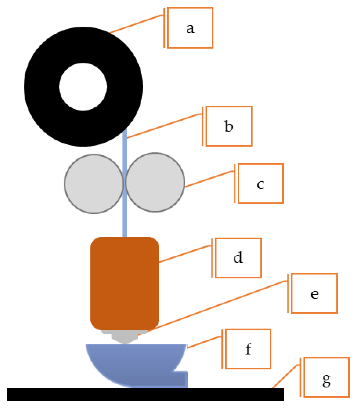
Figure 3. Schematics of FFF equipment: (a) metallic spool, (b) metallic filament, (c) heated chamber, (d) extrusion screw, (e) nozzle, (f) metal AM part, (g) build plate.
As mentioned earlier debinding and sintering are required to create fully metallic parts (Figure 4).
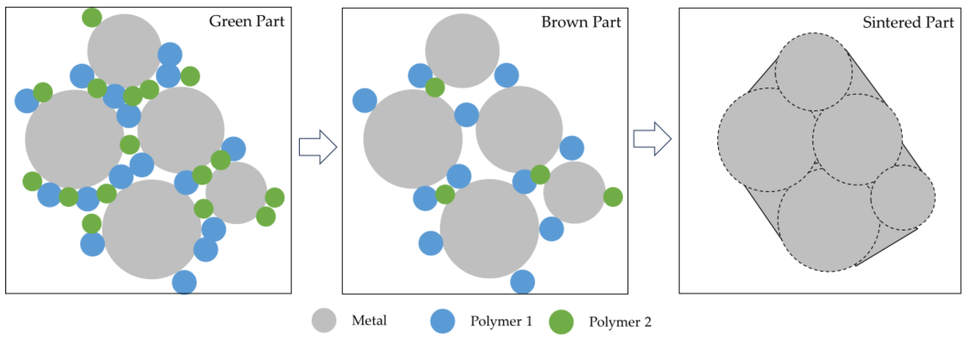
Figure 4. Schematics of debinding and sintering phenomenon.
Debinding optimization is contingent upon the attributes of the binder system and constituents. Multiple debinding methods are available, such as solvent debinding, catalytic debinding, thermal debinding, or combining two or more techniques [38]. The debinding aims to eliminate the binder systems progressively, keeping the produced components’ shape [3][39]. Obtaining proper components after debinding (brown parts) requires a gradual and stable binder removal to avoid defects and shape loss [6][38]. Poor debinding conditions can influence the components’ porosity since carbon residues (resulting from polymer/binder residues) influence the sintering process, promoting bloating, blistering, surface cracking, and large internal voids, which increases the difficulty of achieving a highly dense component [3][27]. The process of transforming the brown part into a fully dense metal component is sintering, where a heat treatment is applied to transform the loosely bound metal powder particles into a bulk material. The temperature used in sintering is below the melting point (between 70 and 90%) of the metal powder, or the major metallic component, to obtain solid components, with all geometries created in the FFF process [6][27]. In sintering, the combination of high temperature and high porosity of the components, created by removing binders during debinding, promotes intense mass transport. As the sintering temperature increases, the system progressively reduces surface energy, forming solid bonds (or necks) between the metal powder particles; these bonds continue to grow by diffusion, thus, decreasing the porosity and densifying the components, resulting in a shrinkage (linear) of components by around 20% [26][70][71]. To optimize the sintering parameters and enhance component consolidation, it is required to monitor the process through microstructural evaluation and mechanical characterization [3][27].
3. Manufacture and Design Considerations for FFF with Metallic Materials
Some specific design considerations must be taken to produce high-quality metallic parts using FFF technology. In fact, compared to the FFF of polymeric materials, applying the process to metallic materials requires special concerns. Metallic materials have different properties than polymers, such as higher melting points, thermal conductivity, and mechanical strength [72]. These properties can affect the part’s production process and final quality. Therefore, selecting a metallic material suitable for FFF and understanding its properties is essential to optimize the manufacturing process [4][23][70]. Another consideration is the capabilities of the FFF equipment. They were designed to produce polymeric materials and may not be suitable for metallic materials [22][35]. It is essential to use equipment specifically designed for producing metallic materials or one that can be modified to produce them [24]. The adhesion to the build plate is also crucial when using metallic materials since they tend to warp more than polymers due to their higher thermal conductivity. Therefore, it is necessary to use a production plate surface that provides good adhesion and prevents warping. The build plates for metallic materials include paper, glass, polyetherimide, and others. The layer height in FFF affects the surface finish and the strength of the finished part. For metallic materials, it is recommended to use a layer height of less than 50% of the nozzle diameter to ensure good adhesion between the layers and avoid delamination [22]. Cooling is also essential since metallic materials require adequate cooling during production to prevent overheating and warping. It is recommended to use equipment with a cooling fan. Finally, after component production, metallic parts produced with FFF may require post-processing to remove support structures, smooth the surface, and improve the part’s mechanical properties. Standard post-processing techniques for metallic parts include sandblasting, polishing, and heat treatment. Regarding supports, some equipment suppliers currently use a ceramic filament to enable an easier separation from parts; the ceramic particles do not sinter due to the higher temperatures required for solid-state diffusion compared to metallic powders [4][5][23].
Unlike traditional manufacturing methods, AM technologies build parts layer-by-layer, using CAD data to create complex geometries and intricate internal structures that would be impossible or difficult to produce with conventional manufacturing methods. Regarding design, it does not make sense to design components as if they were produced with the same principles as traditional manufacturing process structures. The customization potential for the FFF of metallic materials significantly influences design considerations [73]. Several methodologies come into play in any AM process to optimize designs. DfAM is essential, focusing on the layer-by-layer approach, overhangs, and print orientation. Topology optimization (TO) and generative design can generate structural sound and innovative designs [74][75][76][77][78][79]. This is complemented with the use of lattice structures, minimization of support structures, and consideration of anisotropy, which are integral to the process [35][80][81][82][83]. Material selection and heat management play fundamental roles, as does using both CAD software tools and iterative prototyping. Simulation and analysis, along with continuous material and process research, help ensure the success of FFF in metallic materials, making it an optimal solution for highly customized and efficient designs [84][85]. It is a worthy process, as it promptly enables the creation and simulation of thousands of designs and the production of highly customized components with complex shapes [86].
The DfAM approach in the FFF process (similar to other AM processes) involves designing components with the specific capabilities and constraints of the process in mind. DfAM enables the optimization of AM by leveraging its unique capabilities to create printable designs that enhance performance, functionality, and efficiency, allowing the designers to create parts optimized explicitly for AM processes, as shown in the optimized door handle in Figure 5 [77]. It differs from other design processes because it starts with an arbitrary formulation of an initial design concept and combines the algorithms’ critical structures and variables transformed by the algorithms [77][87][88]. It unlocks innovative design possibilities and overcomes traditional manufacturing limitations.
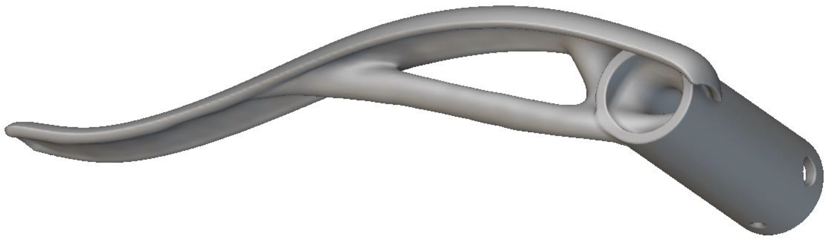
Figure 5. Optimized door handle optimized using DfAM techniques.
DfAM processes entail unique considerations, depending on the process to be used. In direct energy deposition (DED), a process that also uses a laser or electron beam as an energy source, designers must ensure proper cooling of the metal parts during the build process to prevent distortion and minimize the use of support structures; in PBF, thorough selection of powder material and consideration of layer thickness and build orientation is required [3][89]. DfAM to the FFF process is peculiar, takes in the limitations of the process, and considers these constraints like part of the design process, orientation, and overhangs, support structures for steep overhangs, wall thickness, part consolidation, and geometric complexity [78][90][91]. These limitations are common in AM processes and even more evident in FFF. DfAM practices are commonly implemented through specialized software, which provides insights into printability, structural integrity, and potential manufacturing issues, allowing designers to iterate and refine their models [1][49][92]. DfAM incorporates applicable requirements to address and solve the typical conflicts between design and engineering, allowing the creation of parts with well-defined functional requirements to obtain lightweight components and optimized parts by combining design and simulation tools [75][88][91]. DfAM guidelines and best practices consider the unique characteristics and limitations of AM processes, including the need for support structures, layer-by-layer build-up, and the choice of materials.
The FFF process allows the creation of cellular structures, such as porous and lattice designs, through precise control of material deposition. Building these structures layer-by-layer, the FFF enables the infill density adjustments controlling porosity, knowing there is a trade-off between structural integrity and the level of porosity. The choice of filament material is also crucial, as it affects both the structure’s porosity and mechanical properties. Support structures may be needed to prevent collapsing during production, debinding, and sintering, and their removal can pose challenges [93][94][95]. AM lattice structures have outperformed cellular structures produced by other manufacturing methods with equivalent porosity due to the AM process’s greater geometric control and predictability [96][97][98]. By optimizing parts for AM, companies can lower production costs and turnaround times, resulting in faster product development cycles and increased competitiveness in the market.
By adhering to DfAM guidelines, designers can create parts that perform better, cost less, and can be produced more quickly than traditional manufacturing methods [91][99]. With the continuous advancement of AM technology, the importance of DfAM is set to increase even further. DfAM is a crucial aspect of modern manufacturing. Understanding this is overwhelmingly important, as choosing the most suitable process for an intended component application is crucial in AM. Considering factors such as material properties, production volume, lead time, cost, manufacturers, and the constraints from the component requirements (like tolerances, dimensions, wall thickness, and relative density, among others) can make informed decisions and optimize their AM for the specific needs. Stating this, understanding the strengths and limitations of each AM technology is essential in selecting the most suitable one for the intended application of the component.
References
- DebRoy, T.; Wei, H.L.; Zuback, J.S.; Mukherjee, T.; Elmer, J.W.; Milewski, J.O.; Beese, A.M.; Wilson-Heid, A.; De, A.; Zhang, W. Additive manufacturing of metallic components—Process, structure and properties. Prog. Mater. Sci. 2018, 92, 112–224.
- Tuncer, N.; Bose, A. Solid-State Metal Additive Manufacturing: A Review. JOM 2020, 72, 3090–3111.
- Costa, J.; Sequeiros, E.; Vieira, M.T.; Vieira, M. Additive Manufacturing: Material Extrusion of Metallic Parts. U. Porto J. Eng. 2021, 7, 53–69.
- Herderick, E. Additive Manufacturing of Metals: A Review. In Proceedings of the MS&T 2011: Proceedings from the Materials Science & Technology Conference, Columbus, OH, USA, 16–20 October 2011; pp. 1413–1425.
- Gibson, I.; Rosen, D.W.; Stucker, B. Additive Manufacturing Technologies: Rapid Prototyping to Direct Digital Manufacturing; Springer: New York, NY, USA, 2010.
- Gonzalez-Gutierrez, J.; Cano, S.; Schuschnigg, S.; Kukla, C.; Sapkota, J.; Holzer, C. Additive Manufacturing of Metallic and Ceramic Components by the Material Extrusion of Highly-Filled Polymers: A Review and Future Perspectives. Materials 2018, 11, 840.
- Dey, A.; Roan Eagle, I.N.; Yodo, N. A Review on Filament Materials for Fused Filament Fabrication. J. Manuf. Mater. Proc. 2021, 5, 69.
- Behera, M.P.; Dougherty, T.; Singamneni, S. Conventional and Additive Manufacturing with Metal Matrix Composites: A Perspective. Digit. Manuf. Transform. Ind. Towards Sustain. Growth 2019, 30, 159–166.
- Tofail, S.A.M.; Koumoulos, E.P.; Bandyopadhyay, A.; Bose, S.; O’Donoghue, L.; Charitidis, C. Additive manufacturing: Scientific and technological challenges, market uptake and opportunities. Mater. Today 2018, 21, 22–37.
- Zhang, C.; Chen, F.; Huang, Z.; Jia, M.; Chen, G.; Ye, Y.; Lin, Y.; Liu, W.; Chen, B.; Shen, Q.; et al. Additive manufacturing of functionally graded materials: A review. Mater. Sci. Eng. A 2019, 764, 138209.
- Zhang, Y.Z.; Bai, S.Y.; Riede, M.; Garratt, E.; Roch, A. A comprehensive study on fused filament fabrication of Ti-6Al-4V structures. Addit. Manuf. 2020, 34, 101256.
- Kok, Y.; Tan, X.P.; Wang, P.; Nai, M.L.S.; Loh, N.H.; Liu, E.; Tor, S.B. Anisotropy and heterogeneity of microstructure and mechanical properties in metal additive manufacturing: A critical review. Mater. Des. 2018, 139, 565–586.
- Chern, A.H.; Nandwana, P.; McDaniels, R.; Dehoff, R.R.; Liaw, P.K.; Tryon, R.; Duty, C.E. Build orientation, surface roughness, and scan path influence on the microstructure, mechanical properties, and flexural fatigue behavior of Ti–6Al–4V fabricated by electron beam melting. Mater. Sci. Eng. A 2020, 772, 138740.
- Chen, L.Y.; Huang, J.C.; Lin, C.H.; Pan, C.T.; Chen, S.Y.; Yang, T.L.; Lin, D.Y.; Lin, H.K.; Jang, J.S.C. Anisotropic response of Ti-6Al-4V alloy fabricated by 3D printing selective laser melting. Mater. Sci. Eng. A 2017, 682, 389–395.
- Leach, R.K.; Bourell, D.; Carmignato, S.; Donmez, A.; Senin, N.; Dewulf, W. Geometrical metrology for metal additive manufacturing. CIRP Ann.—Manuf. Technol. 2019, 68, 677–700.
- Atzeni, E.; Salmi, A. Economics of additive manufacturing for end-usable metal parts. Int. J. Adv. Manuf. Technol. 2012, 62, 1147–1155.
- Atzeni, E.; Salmi, A. Study on unsupported overhangs of AlSi10Mg parts processed by Direct Metal Laser Sintering (DMLS). J. Manuf. Process. 2015, 20, 500–506.
- Boparai, K.S.; Singh, R.; Singh, H. Development of rapid tooling using fused deposition modeling: A review. Rapid Prototyp. J 2016, 22, 281–299.
- ISO/ASTM52921-13(2019); Standard Terminology for Additive Manufacturing—Coordinate Systems and Test Methodologies. ASTM: West Conshohocken, PA, USA, 2019.
- Shaik, Y.P.; Schuster, J.; Shaik, A. A Scientific Review on Various Pellet Extruders Used In 3D Printing FDM Processes. Open Access Libr. J. 2021, 8, 1–19.
- Kumar, N.; Jain, P.K.; Tandon, P.; Pandey, P.M. Extrusion-based additive manufacturing process for producing flexible parts. J. Braz. Soc. Mech. Sci. Eng. 2018, 40, 1–12.
- Boyle, B.M.; Xiong, P.T.; Mensch, T.E.; Werder, T.J.; Miyake, G.M. 3D printing using powder melt extrusion. Addit. Manuf. 2019, 29, 100811.
- Gibson, M.A.; Mykulowycz, N.M.; Shim, J.; Fontana, R.; Schmitt, P.; Roberts, A.; Ketkaew, J.; Shao, L.; Chen, W.; Bordeenithikasem, P.; et al. 3D printing metals like thermoplastics: Fused filament fabrication of metallic glasses. Mater. Today 2018, 21, 697–702.
- Matsuzaki, R.; Kanatani, T.; Todoroki, A. Multi-material additive manufacturing of polymers and metals using fused filament fabrication and electroforming. Addit. Manuf. 2019, 29, 100812.
- Annoni, M.; Giberti, H.; Strano, M. Feasibility Study of an Extrusion-based Direct Metal Additive Manufacturing Technique. Procedia Manuf. 2016, 5, 916–927.
- Thompson, Y.; Gonzalez-Gutierrez, J.; Kukla, C.; Felfer, P. Fused filament fabrication, debinding and sintering as a low cost additive manufacturing method of 316L stainless steel. Addit. Manuf. 2019, 30, 100861.
- Gonzalez-Gutierez, J.; Godec, D.; Guran, R.; Spoerk, M.; Kukla, C.; Holzer, C. 3d Printing Conditions Determination for Feedstock Used in Fused Filament Fabrication (Fff) of 17-4ph Stainless Steel Parts. Metalurgija 2018, 57, 117–120.
- Frazier, W.E. Metal Additive Manufacturing: A Review. J. Mater. Eng. Perform. 2014, 23, 1917–1928.
- Thompson, S.M.; Bian, L.; Shamsaei, N.; Yadollahi, A. An overview of Direct Laser Deposition for additive manufacturing; Part I: Transport phenomena, modeling and diagnostics. Addit. Manuf. 2015, 8, 36–62.
- Angelopoulos, P.M.; Samouhos, M.; Taxiarchou, M. Functional fillers in composite filaments for fused filament fabrication; a review. Mater. Today Proc. 2021, 37, 4031–4043.
- Singh, P.; Balla, V.K.; Tofangchi, A.; Atre, S.V.; Kate, K.H. Printability studies of Ti-6Al-4V by metal fused filament fabrication (MF3). Int. J. Refract. Met. Hard Mater. 2020, 91, 105249.
- Schatt, W.; Wieters, K.-P. Powder Metallurgy—Processing and Materials; EPMA: Malmo, Sweden, 1997.
- Cano, S.; Gonzalez-Gutierrez, J.; Sapkota, J.; Spoerk, M.; Arbeiter, F.; Schuschnigg, S.; Holzer, C.; Kukla, C. Additive manufacturing of zirconia parts by fused filament fabrication and solvent debinding: Selection of binder formulation. Addit. Manuf. 2019, 26, 117–128.
- Vock, S.; Klöden, B.; Kirchner, A.; Weißgärber, T.; Kieback, B. Powders for powder bed fusion: A review. Prog. Addit. Manuf. 2019, 4, 383–397.
- Wagner, M.A.; Hadian, A.; Sebastian, T.; Clemens, F.; Schweizer, T.; Rodriguez-Arbaizar, M.; Carreño-Morelli, E.; Spolenak, R. Fused filament fabrication of stainless steel structures—From binder development to sintered properties. Addit. Manuf. 2022, 49, 102472.
- Diegel, O.; Nordin, A.; Motte, D. Additive Manufacturing Technologies; Springer: Singapore, 2019; pp. 19–39.
- Gibson, I.; Rosen, D.; Stucker, B.; Khorasani, M. Introduction and Basic Principles. In Additive Manufacturing Technologies; Springer International Publishing: Cham, Switzerland, 2021; pp. 1–21.
- Sequeiros, E.W.; Emadinia, O.; Vieira, M.T.; Vieira, M.F. Development of Metal Powder Hot Embossing: A New Method for Micromanufacturing. Metals 2020, 10, 388.
- Singh, P.; Shaikh, Q.; Balla, V.K.; Atre, S.V.; Kate, K.H. Estimating Powder-Polymer Material Properties Used in Design for Metal Fused Filament Fabrication (DfMF3). JOM 2019, 72, 485–495.
- Emadinia, O.; Vieira, M.T.; Vieira, M.F. Development and characterization of AISI 316L micro parts produced by metal powder hot embossing. Int. J. Adv. Manuf. Technol. 2021, 113, 407–417.
- Sequeiros, E.W.; Ferreira, T.J.; Neto, V.C.; Vieira, M.T.; Vieira, M.F. Microstructural Characterization of Metallic Parts Produced by Hot Embossing. Microsc. Microanal. 2015, 21 (Suppl. S5), 49–50.
- Singh, S.; Prakash, C.; Antil, P.; Singh, R.; Krolczyk, G.; Pruncu, C.I. Dimensionless Analysis for Investigating the Quality Characteristics of Aluminium Matrix Composites Prepared through Fused Deposition Modelling Assisted Investment Casting. Materials 2019, 12, 1907.
- Royer, A.; Barriere, T.; Gelin, J.C. Development and Characterization of a Metal Injection Molding Bio Sourced Inconel 718 Feedstock Based on Polyhydroxyalkanoates. Metals 2016, 6, 89.
- Singh, S.; Ramakrishna, S.; Singh, R. Material issues in additive manufacturing: A review. J. Manuf. Process. 2017, 25, 185–200.
- Volpato, N.; Kretschek, D.; Foggiatto, J.A.; Cruz, C.M.G.D. Experimental analysis of an extrusion system for additive manufacturing based on polymer pellets. Int. J. Adv. Manuf. Technol. 2015, 81, 1519–1531.
- Zhou, Z.; Salaoru, I.; Morris, P.; Gibbons, G.J. Additive manufacturing of heat-sensitive polymer melt using a pellet-fed material extrusion. Addit. Manuf. 2018, 24, 552–559.
- Whyman, S.; Arif, K.M.; Potgieter, J. Design and development of an extrusion system for 3D printing biopolymer pellets. Int. J. Adv. Manuf. Technol. 2018, 96, 3417–3428.
- Xu, C.; Quinn, B.; Lebel, L.L.; Therriault, D.; L’Espérance, G. Multi-Material Direct Ink Writing (DIW) for Complex 3D Metallic Structures with Removable Supports. ACS Appl. Mater. Interfaces 2019, 11, 8499–8506.
- Ang, X.; Tey, J.Y.; Yeo, W.H.; Shak, K.P.Y. A review on metallic and ceramic material extrusion method: Materials, rheology, and printing parameters. J. Manuf. Process. 2023, 90, 28–42.
- Pandya, K.S.; Shindalkar, S.S.; Kandasubramanian, B. Breakthrough to the pragmatic evolution of direct ink writing: Progression, challenges, and future. Prog. Addit. Manuf. 2023, 8, 1303–1328.
- Bonada, J.; Xuriguera, E.; Calvo, L.; Poudelet, L.; Cardona, R.; Padilla, J.A.; Niubó, M.; Fenollosa, F. Analysis of printing parameters for metal additive manufactured parts through Direct Ink Writing process. Procedia Manuf. 2019, 41, 666–673.
- Saadi, M.A.S.R.; Maguire, A.; Pottackal, N.T.; Thakur, M.S.H.; Ikram, M.M.; Hart, A.J.; Ajayan, P.M.; Rahman, M.M. Direct Ink Writing: A 3D Printing Technology for Diverse Materials. Adv. Mater. 2022, 34, 2108855.
- Elkaseer, A.; Chen, K.J.; Janhsen, J.C.; Refle, O.; Hagenmeyer, V.; Scholz, S.G. Material jetting for advanced applications: A state-of-the-art review, gaps and future directions. Addit. Manuf. 2022, 60, 103270.
- Balani, S.B.; Ghaffar, S.H.; Chougan, M.; Pei, E.; Şahin, E. Processes and materials used for direct writing technologies: A review. Results Eng. 2021, 11, 100257.
- Armstrong, M.; Mehrabi, H.; Naveed, N. An overview of modern metal additive manufacturing technology. J. Manuf. Process. 2022, 84, 1001–1029.
- Mostafaei, A.; Steven, E.L.; Ference, J.J.; Schmid, D.E.; Chmielus, M. Binder jetting of a complex-shaped metal partial denture framework. Addit. Manuf. 2018, 21, 63–68.
- Mostafaei, A.; Elliott, A.M.; Barnes, J.E.; Li, F.; Tan, W.; Cramer, C.L.; Nandwana, P.; Chmielus, M. Binder jet 3D printing—Process parameters, materials, properties, modeling, and challenges. Prog. Mater. Sci. 2020, 119, 100707.
- Mostafaei, A.; Neelapu, S.H.V.R.; Kisailus, C.; Nath, L.M.; Jacobs, T.D.B.; Chmielus, M. Characterizing surface finish and fatigue behavior in binder-jet 3D-printed nickel-based superalloy 625. Addit. Manuf. 2018, 24, 200–209.
- Al, C.M.; Yaman, U. Improving the strength of additively manufactured objects via modified interior structure. AIP Conf. Proc. 2017, 1896, 040003.
- Gao, W.; Zhang, Y.B.; Ramanujan, D.; Ramani, K.; Chen, Y.; Williams, C.B.; Wang, C.C.L.; Shin, Y.C.; Zhang, S.; Zavattieri, P.D. The status, challenges, and future of additive manufacturing in engineering. Comput. Aided. Des. 2015, 69, 65–89.
- Rane, K.; Strano, M. A comprehensive review of extrusion-based additive manufacturing processes for rapid production of metallic and ceramic parts. Adv. Manuf. 2019, 7, 155–173.
- Thompson, M.K.; Moroni, G.; Vaneker, T.; Fadel, G.; Campbell, R.I.; Gibson, I.; Bernard, A.; Schulz, J.; Graf, P.; Ahuja, B.; et al. Design for Additive Manufacturing: Trends, opportunities, considerations, and constraints. CIRP. Ann.—Manuf. Technol. 2016, 65, 737–760.
- Turner, B.N.; Strong, R.; Gold, S.A. A review of melt extrusion additive manufacturing processes: I. Process design and modeling. Rapid Prototyp. J. 2014, 20, 192–204.
- Greeff, G.P.; Schilling, M. Single print optimisation of fused filament fabrication parameters. Int. J. Adv. Manuf. Technol. 2018, 99, 845–858.
- Hertle, S.; Kleffel, T.; Worz, A.; Drummer, D. Production of polymer-metal hybrids using extrusion-based additive manufacturing and electrochemically treated aluminum. Addit. Manuf. 2020, 33, 101135.
- Kumar, L.J.; Pandey, P.M.; Wimpenny, D.I. 3D Printing and Additive Manufacturing Technologies; Springer: Berlin/Heidelberg, Germany, 2019; Volume 311.
- Patel, A.; Taufik, M. Extrusion-Based Technology in Additive Manufacturing: A Comprehensive Review. Arab. J. Sci. Eng. 2022.
- Hui, W.; Shao, C.; Zhang, Y.; Zhao, X.; Weng, Y. Microstructure and mechanical properties of medium Mn steel containing 3%Al processed by warm rolling. Mater. Sci. Eng. A 2017, 707, 501–510.
- Nath, P.; Olson, J.D.; Mahadevan, S.; Lee, Y.-T.T. Optimization of fused filament fabrication process parameters under uncertainty to maximize part geometry accuracy. Addit. Manuf. 2020, 35, 101331.
- Yadav, A.; Rohru, P.; Babbar, A.; Kumar, R.; Ranjan, N.; Chohan, J.S.; Kumar, R.; Gupta, M. Fused filament fabrication: A state-of-the-art review of the technology, materials, properties and defects. Int. J. Interact. Des. Manuf. (IJIDeM) 2022, 17, 2867–2889.
- Notzel, D.; Hanemann, T. New Feedstock System for Fused Filament Fabrication of Sintered Alumina Parts. Materials 2020, 13, 4461.
- Mulholland, T.; Goris, S.; Boxleitner, J.; Osswald, T.A.; Rudolph, N. Fiber Orientation Effects in Fused Filament Fabrication of Air-Cooled Heat Exchangers. JOM J. Miner. Met. Mater. Soc. (TMS) 2018, 70, 298.
- Zanjanijam, A.R.; Major, I.; Lyons, J.G.; Lafont, U.; Devine, D.M. Fused Filament Fabrication of PEEK: A Review of Process-Structure-Property Relationships. Polymers 2020, 12, 1665.
- Li, S.; Wei, H.; Yuan, S.; Zhu, J.; Li, J.; Zhang, W. Collaborative optimization design of process parameter and structural topology for laser additive manufacturing. Chin. J. Aeronaut. 2023, 36, 456–467.
- Gebisa, A.W.; Lemu, H.G. Design for manufacturing to design for Additive Manufacturing: Analysis of implications for design optimality and product sustainability. Procedia Manuf. 2017, 13, 724–731.
- Sossou, G.; Demoly, F.; Montavon, G.; Gomes, S. An additive manufacturing oriented design approach to mechanical assemblies. J. Comput. Des. Eng. 2017, 5, 3–18.
- Mata, M.; Pinto, M.; Costa, J. Topological Optimization of a Metal Extruded Doorhandle using nTopology. U. Porto J. Eng. 2023, 9, 42–54.
- Schmelzle, J.; Kline, E.V.; Dickman, C.J.; Reutzel, E.W.; Jones, G.; Simpson, T.W. (Re)Designing for Part Consolidation: Understanding the Challenges of Metal Additive Manufacturing. J. Mech. Des. 2015, 137, 111404–111412.
- Leary, M.; Downing, D.; Lozanovski, B.; Harris, J. 5—Design principles. In Fundamentals of Laser Powder Bed Fusion of Metals; Yadroitsev, I., Yadroitsava, I., du Plessis, A., MacDonald, E., Eds.; Elsevier: Amsterdam, The Netherlands, 2021; pp. 119–154.
- Dara, A.; Johnney Mertens, A.; Raju Bahubalendruni, M.V.A. Characterization of penetrate and interpenetrate tessellated cellular lattice structures for energy absorption. Proc. Inst. Mech. Eng. Part L J. Mater. Des. Appl. 2022, 237, 906–913.
- Chouhan, G.; Gunji, B.M.; Bidare, P.; Ramakrishna, D.; Kumar, R. Experimental and numerical investigation of 3D printed bio-inspired lattice structures for mechanical behaviour under Quasi static loading conditions. Mater. Today Commun. 2023, 35, 105658.
- Ramakrishna, D.; Bala Murali, G. Bio-inspired 3D-printed lattice structures for energy absorption applications: A review. Proc. Inst. Mech. Eng. Part L J. Mater. Des. Appl. 2022, 237, 503–542.
- Mazur, M.; Leary, M.; McMillan, M.; Sun, S.; Shidid, D.; Brandt, M. Mechanical properties of Ti6Al4V and AlSi12Mg lattice structures manufactured by Selective Laser Melting (SLM). In Laser Additive Manufacturing; Woodhead Publishing: Cambridge, UK, 2017; pp. 119–161.
- Nyamekye, P.; Unt, A.; Salminen, A.; Piili, H. Integration of Simulation Driven DfAM and LCC Analysis for Decision Making in L-PBF. Metals 2020, 10, 1179.
- McMillan, M.; Leary, M.; Brandt, M. Computationally efficient finite difference method for metal additive manufacturing: A reduced-order DFAM tool applied to SLM. Mater. Des. 2017, 132, 226–243.
- Vuillemot, R.; Huron, S. Glitches as a generative design process. In Proceedings of the 2017 IEEE VIS Arts Program (VISAP), Phoenix, AZ, USA, 1–6 October 2017.
- Cui, J.; Tang, M.X. Towards generative systems for supporting product design. Int. J. Des. Eng. 2017, 7, 1–16.
- Oliveira, C.; Maia, M.; Costa, J. Production of an Office Stapler by Material Extrusion Process, using DfAM as Optimization Strategy. U. Porto J. Eng. 2023, 9, 28–41.
- Wang, X.; Xu, S.; Zhou, S.; Xu, W.; Leary, M.; Choong, P.; Qian, M.; Brandt, M.; Xie, Y.M. Topological design and additive manufacturing of porous metals for bone scaffolds and orthopaedic implants: A review. Biomaterials 2016, 83, 127–141.
- Mass, Y.; Amir, O. Topology optimization for additive manufacturing: Accounting for overhang limitations using a virtual skeleton. Addit. Manuf. 2017, 18, 58–73.
- Yang, S.; Zhao, Y.F. Additive manufacturing-enabled design theory and methodology: A critical review. Int. J. Adv. Manuf. Technol. 2015, 80, 327–342.
- Langelaar, M. An additive manufacturing filter for topology optimization of print-ready designs. Struct. Multidiscip. Optim. 2017, 55, 871–883.
- Dara, A.; Bahubalendruni, M.V.A.R.; Johnney Mertens, A.; Balamurali, G. Numerical and experimental investigations of novel nature inspired open lattice cellular structures for enhanced stiffness and specific energy absorption. Mater. Today Commun. 2022, 31, 103286.
- Samson, S.; Tran, P.; Marzocca, P. Design and modelling of porous gyroid heatsinks: Influences of cell size, porosity and material variation. Appl. Therm. Eng. 2023, 235, 121296.
- Riza, S.H.; Masood, S.H.; Wen, C.E.; Ruan, D.; Xu, S.Q. Dynamic behaviour of high strength steel parts developed through laser assisted direct metal deposition. Mater. Des. 2014, 64, 650–659.
- Maconachie, T.; Leary, M.; Lozanovski, B.; Zhang, X.; Qian, M.; Faruque, O.; Brandt, M. SLM lattice structures: Properties, performance, applications and challenges. Mater. Des. 2019, 183, 108137.
- Cheng, L.; Zhang, P.; Biyikli, E.; Bai, J.; Pilz, S.; To, A.C. Integration of topology optimization with efficient design of additive manufactured cellular structures. In Proceedings of the Solid Freeform Fabrication (SFF) Conference, Austin, TX, USA, 10–12 August 2015.
- Park, S.I.; Rosen, D.W.; Choi, S.K.; Duty, C.E. Effective Mechanical Properties of Lattice Material Fabricated by Material Extrusion Additive Manufacturing. In Proceedings of the ASME International Design Engineering Technical Conferences and Computers and Information in Engineering Conference, Buffalo, NY, USA, 17–20 August 2014; Volumes 1–4, pp. 12–23.
- Yang, L.; Hsu, K.; Baughman, B.; Godfrey, D.; Medina, F.; Menon, M.; Wiener, S. Additive Manufacturing of Metals: The Technology, Materials, Design and Production; Springer: Berlin/Heidelberg, Germany, 2017.
More
Information
Subjects:
Metallurgy & Metallurgical Engineering
Contributors
MDPI registered users' name will be linked to their SciProfiles pages. To register with us, please refer to https://encyclopedia.pub/register
:
View Times:
845
Revisions:
2 times
(View History)
Update Date:
12 Dec 2023
Table of Contents


Notice
You are not a member of the advisory board for this topic. If you want to update advisory board member profile, please contact office@encyclopedia.pub.
OK
Confirm
Only members of the Encyclopedia advisory board for this topic are allowed to note entries. Would you like to become an advisory board member of the Encyclopedia?
Yes
No
${ textCharacter }/${ maxCharacter }
Submit
Cancel
Back
Comments
${ item }
|
${ item.createdUser.fullName }
${ item.createdAt }
${ item.vote }
${ item.reply }
Delete
${ reply.createdUser.fullName }
${ reply.createdAt }
${ reply.vote }
Delete
There is no reply to this comment~
${ item.replyTextCharacter }/${ item.replyMaxCharacter }
Submit
Cancel
More
No more~
There is no comment~
${ textCharacter }/${ maxCharacter }
Submit
Cancel
${ selectedItem.replyTextCharacter }/${ selectedItem.replyMaxCharacter }
Submit
Cancel
Confirm
Are you sure to Delete?
Yes
No