Your browser does not fully support modern features. Please upgrade for a smoother experience.
Submitted Successfully!
 +1 credit
Thank you for your contribution! You can also upload a video entry or images related to this topic.
For video creation, please contact our Academic Video Service.
| Version | Summary | Created by | Modification | Content Size | Created at | Operation |
|---|---|---|---|---|---|---|
| 1 | Matthew Soon Kiat Yeo | -- | 2327 | 2023-10-12 12:45:56 | | | |
| 2 | Rita Xu | Meta information modification | 2327 | 2023-10-13 03:36:58 | | |
Video Upload Options
We provide professional Academic Video Service to translate complex research into visually appealing presentations. Would you like to try it?
Cite
If you have any further questions, please contact Encyclopedia Editorial Office.
Yeo, M.S.K.; Pey, J.J.J.; Elara, M.R. Passive Auto-Tactile Heuristic Tiles. Encyclopedia. Available online: https://encyclopedia.pub/entry/50194 (accessed on 15 July 2026).
Yeo MSK, Pey JJJ, Elara MR. Passive Auto-Tactile Heuristic Tiles. Encyclopedia. Available at: https://encyclopedia.pub/entry/50194. Accessed July 15, 2026.
Yeo, Matthew S. K., Javier J. J. Pey, Mohan Rajesh Elara. "Passive Auto-Tactile Heuristic Tiles" Encyclopedia, https://encyclopedia.pub/entry/50194 (accessed July 15, 2026).
Yeo, M.S.K., Pey, J.J.J., & Elara, M.R. (2023, October 12). Passive Auto-Tactile Heuristic Tiles. In Encyclopedia. https://encyclopedia.pub/entry/50194
Yeo, Matthew S. K., et al. "Passive Auto-Tactile Heuristic Tiles." Encyclopedia. Web. 12 October, 2023.
Copy Citation
Mobile service robots often have to work in dynamic and cluttered environments. Multiple safety hazards exist for robots in such work environments, which visual sensors may not detect in time before collisions or robotic damage. An alternative hazard alert system using tactile methods is explored to pre-emptively convey surrounding spatial information to robots working in complex environments or under poor lighting conditions.
tactile paving
robot-inclusive
hazard detection
1. Introduction
Robots are deployed in more public spaces, with the range of tasks performed by robots increasing over time [1][2][3], especially those tasks that are considered dull, dirty, and dangerous to humans [4]. In particular, mobile service robots are conducting more cleaning, cleanliness auditing [5] and inspection tasks in built-up transit zones like hotel lobbies, airports, and restaurants [6][7]. These mobile service robots compensate for the lack of manpower for mundane and tedious jobs [8][9]. Robots encounter operational inefficiency if the existing environment is not catered for their deployment, along with the spatial obstacles they can encounter. Robot stoppage, damage to property and robots through collisions, and reduced robotic productivity are some problems that occur if the situation is not addressed.
Existing robotic detection methods that rely solely on visual means are limited by occlusion, lighting conditions, and image quality [10][11]. The sensors installed on robots let them perceive their surroundings and the hazards in their workspace. Mobile robots utilize a variety of sensors for them to localize themselves within their deployed workspace [12] and move to the next point of interest based on their sensor inputs and programming. Some of the most common localization techniques involve Simultaneous Localization And Mapping (SLAM) [13], landmark recognition or beacon arrays [14], the use of fiducial markers [15][16], and the Global Positioning System (GPS) [17]. A summary of these methods and their limitations is seen in Table 1. Error information obtained from the sensors could lead to errors in the robot’s localization or false positives in detecting the surrounding hazards, depending on the robot’s software [18][19][20].
Table 1. Typical visual localization methods used by existing mobile robot platforms.
| Localization Method | Description | Limitations |
|---|---|---|
| SLAM [13] | Use of LIDAR sensors to generate two-dimensional maps of robot and its surroundings |
|
| Robot beacon array [14] | Usage of Wifi/RFID and other wireless technologies to help robot to triangulate its location within a given space |
|
| Fiducial markers [15] | Visual (usually monochromatic) markers placed at strategic locations for robot to detect and localize |
|
Robots inevitably run into obstacles in their environment during operation, be it objects in their path (spatial hazards) or items that cause detection problems in the robot’s input sensors (perceptional hazards). A non-exhaustive list of spatial hazard classes encountered by mobile service robots is categorized in Table 2. The examples listed are not exhaustive but contain the general types of hazards that mobile robots encounter during operation.
Table 2. Categories of robotic indoor hazards and robots’ responses upon encounter.
| Spatial Hazards to Robots | Examples | Common Responses by Robots |
|---|---|---|
| Static obstacles |
|
|
| Moving/transient obstacles |
|
|
| Level changes/inclines |
|
|
| Narrow passage |
|
|
| Sharp turns |
|
|
| Overhangs |
|
|
Robot designers should consider alternative methods for hazard detection for robots to sense their environment instead of solely looking upon visual means of spatial hazard detection. In light of the listed limitations in visual means, tactile means could be explored for object localization and detection [21] and even be combined with vision sensors [22][23][24][25] for more comprehensive hazard detection of obstacles in the environment. In [26], various modified tactile sensors were experimented upon in different simulations to show the viability of using tactile sensors in robotics for hazard perception.
2. Advantages of Tactile Sensing Usage by Robots
There are numerous benefits to using tactile sensing in hazard detection for robots. The main advantages that tactile sensing could provide are cheaper hardware implementation [27][28] and reduced computational load compared with visual methods [29][30].
The use of tactile methods as sensor inputs could reduce hardware implementation costs, with less reliance on expensive visual detection equipment such as LIDAR or depth cameras. The resources used for such robotic components, such as rare metals and plastics, would be freed for other uses. By bringing down the overall costs of building robots, more robots could then be built with the same amount of financial capital for sales or deployment, improving cost effectiveness and overall production output [30].
Tactile sensing could cut down the computational load that the robotic processors operate with due to simplified data types being parsed, oftentimes by having the system detect the tactile changes upon the surface themselves as Boolean states, instead of having to deal with visual clutter, sub-optimal lighting conditions, or visual inputs with grainy image resolutions.
Visual clutter or downgraded image resolution can increase the time or computational memory required for the robot to identify and detect hazards in its surroundings. Tactile sensing could also complement visual sensing to reduce error rates in the spatial hazard detection of the robot’s surroundings [31][32] as a backup when the visual input cannot be used effectively by the robot.
Input data gathered using tactile sensing would also be unaffected by the local lighting conditions of the area. This could enable robotic aid equipped with these tactile sensors to be deployed in regions with low lux or outdoor areas illuminated with bright lights without hampering the detection of hazards within its surroundings.
There is thus the potential and opportunity to adapt this tactile paving system to aid robotic deployment to both improve usage rates and refine the type of information conveyed by the updated tactile indicators.
Robots could thus benefit greatly from a tactile hazard alert system and its corresponding interpretation program to have a robust tactile hazard detection method. To achieve that, researchers can look into existing tactile systems used for conveying information on hazards present in the environment. One of the successful existing tactile paving systems effectively aids visually impaired or blind (VIB) users in navigating to specific amenities such as elevators and service counters in public settings. It also helps VIB people avoid obstacles in their path [33]. Existing tactile sensing infrastructure is underutilized by the general population but is still needed by VIB people for their daily commute. Then, tactile sensing could also enable robots to be deployed in areas with extreme lighting conditions or in restricted areas that prohibit visual mapping.
3. Existing Tactile Paving System for Visually Impaired/Blind People
The tactile paving system was created by Seiichi Miyake in 1965 and implemented in Okayama, Japan, in 1967 [34]. Standards for the design and implementation of tactile paving are referenced from ISO/FDIS 23599 [35] and CEN/TS 15209 [36]. Countries such as Singapore [37][38], New Zealand [39], the United Kingdom (UK) [40], the United States [41], and Japan [42] have their own customized national standards for tactile paving [43][44].
These tactile paving tiles are usually brightly colored in red or yellow for distinct color contrast for locations near level changes [45][46][47] or can be colored to blend into the surrounding floor material [46]. Tactile paving is commonly made from durable materials, such as steel, granite, or hard rubber. This allows it to withstand constant foot traffic; heavy rolling loads; extreme outdoor UV levels; and other weather elements, such as wind and rain.
The existing tactile paving tiles commonly use round bumps or long, slender directional bumps [48][49]. There are specific patterns of tactile paving that convey different information types. One design provides directional cues for VIB people to guide them towards amenities. Another design denotes warnings of nearby level changes. Other designs of tactile paving tiles serve to delineate the boundary between cycling tracks and pedestrian walkways located beside each other. The distance between tactile paving and the actual hazard is dependent on the country’s requirements [41][44].
Blister tactile paving tiles are typical tactile ground surface indicators (TGSIs) that have rows of flat-topped blisters placed in a rectilinear grid pattern, as seen in Figure 1A. This type of tactile paving are usually located at pedestrian crossings. They alert VIB users about the interface between footpaths and roadways or about locations with crossing gaps. The blisters are raised, truncated cones. Each blister is about 5 ± 0.5 mm high and 35–50 mm away from the others. The blisters’ base diameter is about 30–35 mm, with a diameter of 25 mm at the top.
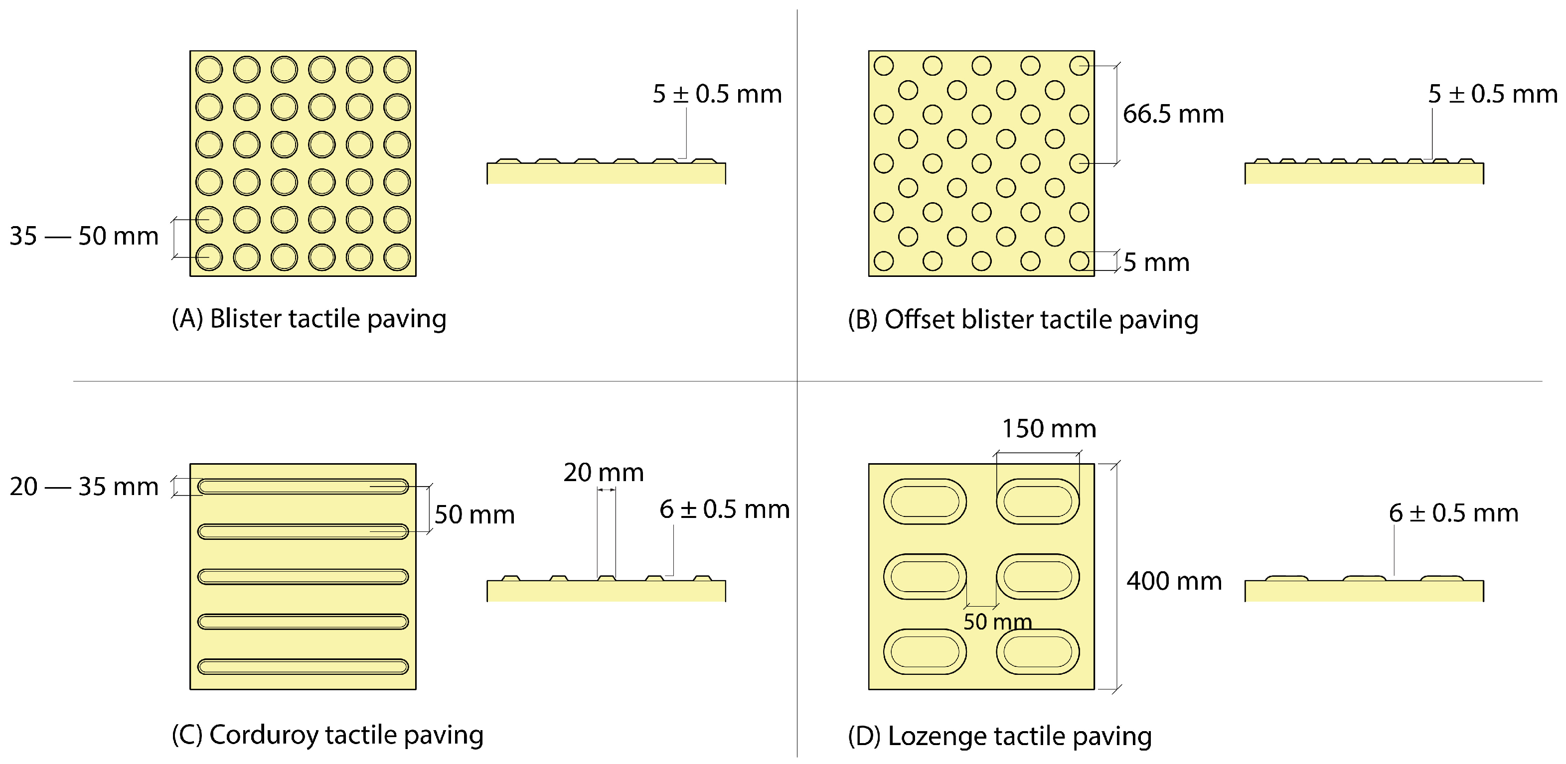
Figure 1. Common types of tactile paving tiles in existence.
Offset blister tiles are a specific type of blister tactile paving that warns of platform edges or cliffs ahead. The blisters are laid out in a diamond grid pattern instead of the rectilinear grid of the normal blister tiles, as seen in Figure 1B. The tile’s blisters are spaced about 66.5 mm from each other. These tiles are usually set back about 50 cm from platform edges to inform VIB users about the hazard ahead to let them stop or slow down before the level’s edge.
Corduroy tactile paving tiles are made of flat-topped bars with rounded ends to convey directional cues. These bars are 6 ± 0.5 mm high and about 20 mm in width and are spaced 50 mm apart, as shown in Figure 1C. The length of the raised bars is dependent on the tile’s length and any local tactile paving standards. Corduroy paving aligned parallel to the direction of travel denotes a safe path for VIB users to follow along. Corduroy paving tiles that are laid perpendicularly to the direction of travel are often located near level changes (such as staircase landings, ramps, level crossings, and intersections of footpaths and roadways) to warn nearby users of the presence of hazards ahead.
Lozenge paving tiles are a subtype of corduroy tactile paving that functions as a platform-edge warning surface, with rows of 6 ± 0.5 mm rounded lozenge shapes, as seen in Figure 1D. These lozenge tiles are arranged parallel to the platform edge and set back from the platform edge to give VIB users time to stop and change direction once they come into contact with lozenge tactile paving.
Cycleway tactile paving is made of multiple, continuous, raised, flat-topped stripes. Each stripe is 5 ± 0.5 mm high, about 30 mm wide, and spaced 70 mm apart. The central delineator strip is 12–20 mm high, 150 mm wide, 5 cm in width with sloping sides. The delineator strip is usually colored in white for visual contrast for sighted cyclists. Cycleway tactile paving is located on any shared route where the pedestrian side is not physically separated from the cyclist side. They are often located at the end of a shared segregated route, at regular intervals along its length, and at junctions intersecting with other pedestrian or cyclist routes.
Directional or guidance tactile paving tiles are a series of raised, flat-topped bars running in the direction of pedestrian travel. The bars are 5–6 mm in height, 35 mm wide, and spaced 45 mm apart. They are implemented in zones as obstacle avoidance or directional guides to guide VIB people to amenities.
Directional and blister tiles are often used in combination, such as those seen in Figure 2, to communicate a safe path to VIB people in public areas with multiple spatial hazards. At junctions where there is a directional change, a 2 × 2 grid of four blister tiles is usually used to indicate that there is a fork in the tactile path for VIB users. Drop-off points and pedestrian crossings also require blister tactile paving that spans the pavement–road interface.
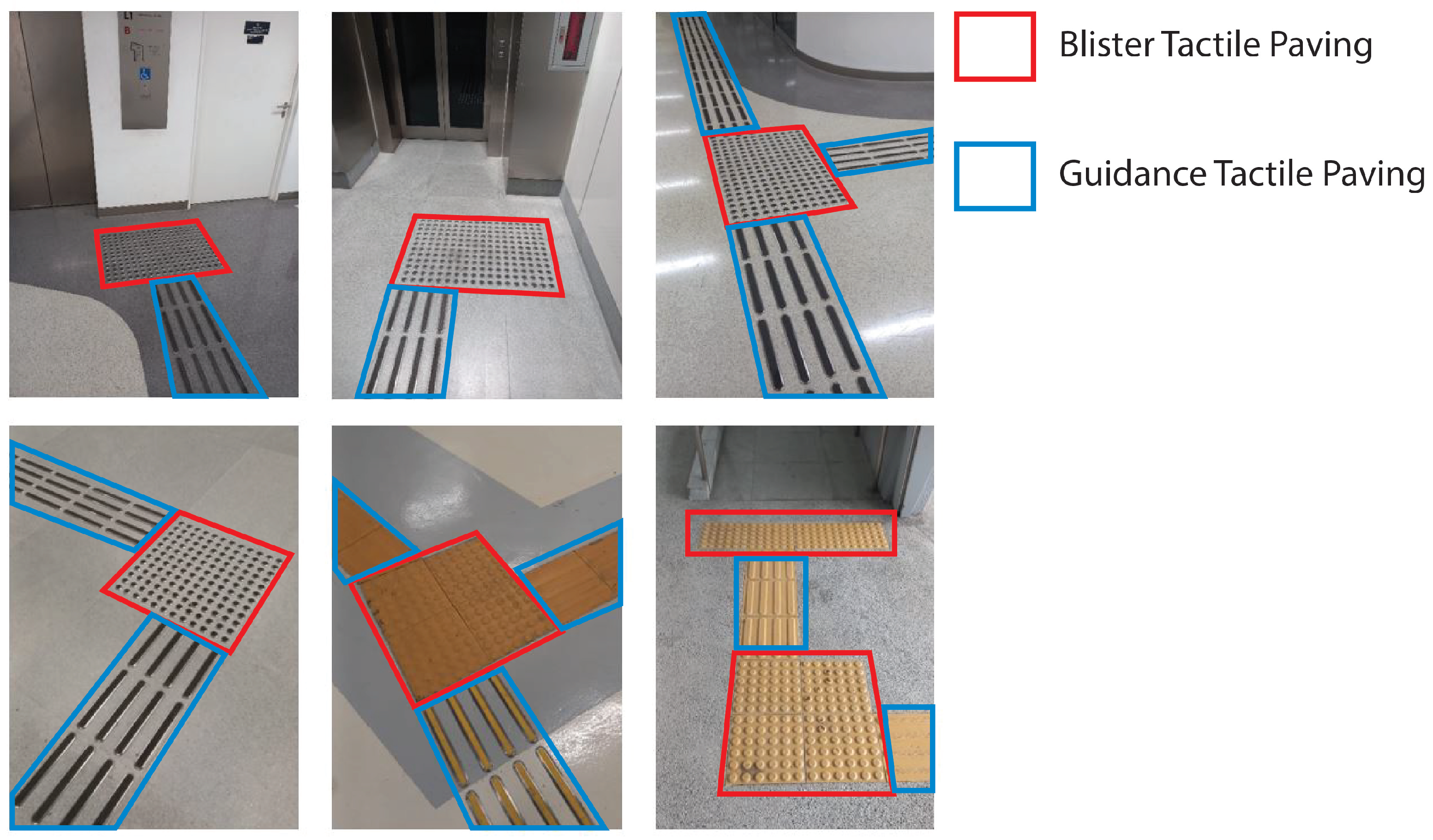
Figure 2. Examples of existing tactile paving used in combination to denote turns, path bifurcations, or areas of interest.
An overview of the various tactile paving types and functions is shown in Table 3, referenced from [43][48]. Most countries implement blister and directional tiles more for widespread usage compared with the other tile variants.
Table 3. Summary of existing tactile paving types.
| Tactile Indicator Type | Typical Locations | Usage/Function |
|---|---|---|
| Blister paving | Before crossing interfaces | Alerting VIB users of intersection ahead and to proceed with care |
| Offset blister paving | Near level change of railway platform edge |
Warning VIB users of platform edges/level drop |
| Corduroy hazard warning paving |
Near obstacles or level changes |
Warning VIB users of hazards ahead, to proceed with care |
| Lozenge paving | On-street platform edges | Warning VIB users of platform edge of light transport systems |
| Cycleway paving | Beginning and end of cycleway and pedestrian intersections |
Alerting VIB users of pedestrian pathways and cycleway paths |
| Guidance/ directional paving |
Safe route around obstacles | Identifying safe route for VIB users, providing directional cues, and avoiding obstacles |
Current tactile paving only provides limited tactile information on the surrounding spatial hazards to VIB people. More could be added to such a system to enhance the information conveyed to both humans and robots on the types of spatial hazards in the vicinity. Information such as the type of hazard and how far it is from the current tactile paving could be encoded upon the modified tactile paving. Examples could be warning VIB users and robots of level changes like stairs and slopes, or zones with high traffic, and the corresponding distance from the tactile paving’s location. Some existing tactile paving structures have installation errors and differences in applications among countries [50][51], which leads to improper or unsafe paths [52] for VIB users. Consequences of such counterproductive tactile aid placement could be directing VIB people into obstacles planted in the way or guiding them to places with numerous fast-moving obstacles, leading to collisions and injuries. Having an updated tactile paving catalog and proper installation layouts could help provide a way of correcting these errors by implementing the updated system.
References
- Ciupe, V.; Maniu, I. New trends in service robotics. In New Trends in Medical and Service Robots: Theory and Integrated Applications; Springer: Berlin/Heidelberg, Germany, 2014; pp. 57–74.
- Hajduk, M.; Koukolová, L. Trends in industrial and service robot application. Appl. Mech. Mater. 2015, 791, 161–165.
- Sun, Y.; Wang, R. The research framework and evolution of service robots. J. Comput. Inf. Syst. 2022, 62, 598–608.
- Trevelyan, J.; Hamel, W.R.; Kang, S.C. Robotics in hazardous applications. In Springer Handbook of Robotics; Springer: Berlin/Heidelberg, Germany, 2016; pp. 1521–1548.
- Pey, J.J.J.; Povendhan, A.P.; Pathmakumar, T.; Elara, M.R. Robot-aided Microbial Density Estimation and Mapping. In Proceedings of the 2022 IEEE/RSJ International Conference on Intelligent Robots and Systems (IROS), Kyoto, Japan, 23–27 October 2022; pp. 2265–2272.
- Wirtz, J.; Kunz, W.; Paluch, S. The service revolution, intelligent automation and service robots. Eur. Bus. Rev. 2021, 29, 909.
- Yörük, T.; Akar, N.; Özmen, N.V. Research trends on guest experience with service robots in the hospitality industry: A bibliometric analysis. Eur. J. Innov. Manag. 2023; ahead of print.
- Shukla, M.; Shukla, A.N. Growth of robotics industry early in 21st century. Int. J. Comput. Eng. Res. 2012, 2, 1554–1558.
- Qureshi, M.O.; Syed, R.S. The impact of robotics on employment and motivation of employees in the service sector, with special reference to health care. Saf. Health Work. 2014, 5, 198–202.
- Yang, J.; Wang, C.; Jiang, B.; Song, H.; Meng, Q. Visual perception enabled industry intelligence: State of the art, challenges and prospects. IEEE Trans. Ind. Informatics 2020, 17, 2204–2219.
- Hua, C. A Review of Visual Perception for Mobile Robot Navigation: Methods, Limitation, and Applications. In Proceedings of the 2022 2nd International Conference on Algorithms, High Performance Computing and Artificial Intelligence (AHPCAI), Guangzhou, China, 21–23 October 2022; pp. 729–737.
- Morar, A.; Moldoveanu, A.; Mocanu, I.; Moldoveanu, F.; Radoi, I.E.; Asavei, V.; Gradinaru, A.; Butean, A. A comprehensive survey of indoor localization methods based on computer vision. Sensors 2020, 20, 2641.
- Dey, S.; Mukherjee, A. Robotic slam: A review from fog computing and mobile edge computing perspective. In Proceedings of the Adjunct Proceedings of the 13th International Conference on Mobile and Ubiquitous Systems: Computing Networking and Services, Hiroshima, Japan, 28 November–1 December 2016; pp. 153–158.
- Filliat, D.; Meyer, J.A. Map-based navigation in mobile robots:: I. a review of localization strategies. Cogn. Syst. Res. 2003, 4, 243–282.
- Lim, H.; Lee, Y.S. Real-time single camera SLAM using fiducial markers. In Proceedings of the 2009 ICCAS-SICE, Fukuoka City, Japan, 18–21 August 2009; pp. 177–182.
- Figat, J.; Kasprzak, W. NAO-mark vs QR-code Recognition by NAO Robot Vision. In Progress in Automation, Robotics and Measuring Techniques; Springer: Berlin/Heidelberg, Germany, 2015; pp. 55–64.
- Shen, L.; Stopher, P.R. Review of GPS travel survey and GPS data-processing methods. Transp. Rev. 2014, 34, 316–334.
- Panchpor, A.A.; Shue, S.; Conrad, J.M. A survey of methods for mobile robot localization and mapping in dynamic indoor environments. In Proceedings of the 2018 Conference on Signal Processing And Communication Engineering Systems (SPACES), Vijayawada, India, 4–5 January 2018; pp. 138–144.
- Skrzypczyński, P. Mobile robot localization: Where we are and what are the challenges? In Automation 2017: Innovations in Automation, Robotics and Measurement Techniques 1; Springer: Berlin/Heidelberg, Germany, 2017; pp. 249–267.
- Hernández, A.C.; Gómez, C.; Crespo, J.; Barber, R. Object detection applied to indoor environments for mobile robot navigation. Sensors 2016, 16, 1180.
- Argall, B.D.; Billard, A.G. A survey of Tactile Human–Robot Interactions. Robot. Auton. Syst. 2010, 58, 1159–1176.
- Luo, S.; Bimbo, J.; Dahiya, R.; Liu, H. Robotic tactile perception of object properties: A review. Mechatronics 2017, 48, 54–67.
- Lee, M.H.; Nicholls, H.R. Review Article Tactile sensing for mechatronics—A state of the art survey. Mechatronics 1999, 9, 1–31.
- Lee, J.T.; Bollegala, D.; Luo, S. “Touching to see” and “seeing to feel”: Robotic cross-modal sensory data generation for visual-tactile perception. In Proceedings of the 2019 International Conference on Robotics and Automation (ICRA), Montreal, QC, Canada, 20–24 May 2019; pp. 4276–4282.
- Alatise, M.B.; Hancke, G.P. A Review on Challenges of Autonomous Mobile Robot and Sensor Fusion Methods. IEEE Access 2020, 8, 39830–39846.
- Taddeucci, D.; Laschi, C.; Lazzarini, R.; Magni, R.; Dario, P.; Starita, A. An approach to integrated tactile perception. In Proceedings of the International Conference on Robotics and Automation, Albuquerque, NM, USA, 20–25 April 1997; Volume 4, pp. 3100–3105.
- Nicholls, H.R.; Lee, M.H. A survey of robot tactile sensing technology. Int. J. Robot. Res. 1989, 8, 3–30.
- Dargahi, J.; Najarian, S. Advances in tactile sensors design/manufacturing and its impact on robotics applications—A review. Ind. Robot. Int. J. 2005, 32, 268–281.
- Lee, M.H. Tactile sensing: New directions, new challenges. Int. J. Robot. Res. 2000, 19, 636–643.
- Dahiya, R.S.; Valle, M.; Postolache, O.; Pereira, J.M.D. Tactile sensing for robotic applications. Sens. Focus Tactile Force Stress Sens. 2008, 298–304.
- Chi, C.; Sun, X.; Xue, N.; Li, T.; Liu, C. Recent progress in technologies for tactile sensors. Sensors 2018, 18, 948.
- Zou, L.; Ge, C.; Wang, Z.J.; Cretu, E.; Li, X. Novel tactile sensor technology and smart tactile sensing systems: A review. Sensors 2017, 17, 2653.
- Rosa, M.P.; de Mello, G.S.; Morato, S. Tactile paving surfaces at bus stops. J. Access. Des. All 2021, 11, 259–294.
- Sakaguchi, R.; Takasu, S.; Akiyama, T. Study concerning the colours of tactile blocks for the visually handicapped-visibility for the visually handicapped and scenic congruence for those with ordinary sight and vision. In Proceedings of the JIPEA World Congress, Tohoku, Japan, 28 May–10 June 2000; pp. 453–462.
- ISO. Assistive Products for Blind and Vision-Impaired Persons; ISO: Geneva, Switzerland, 2012.
- CEN/TS 15209:2008; Tactile Paving Surface Indicators Produced from Concrete, Clay and Stone. European Committee for Standardization (CEN): Brussels, Belgium, 2013.
- Division, D.B.C. Tactile Poster v0.6—Land Transport Authority (LTA). 2015. Available online: https://www.lta.gov.sg/content/dam/ltagov/industry_innovations/industry_matters/development_construction_resources/quick_guide_series_for_development_related_proposals/TactileTilesPosterV0.6.pdf (accessed on 8 September 2023).
- Song, S.K. Singapore Government Circular. 2006. Available online: https://www.corenet.gov.sg/einfo/Uploads/Circulars/CLTA060921.pdf (accessed on 4 June 2023).
- Standards New Zealand, S.A. Australian/New Zealand Standard. 2002. Available online: https://www.saiglobal.com/pdftemp/previews/osh/as/as1000/1400/n14284.pdf (accessed on 7 August 2023).
- BSI. BS 7997:2003. 2003. Available online: https://www.roadstone.ie/wp-content/uploads/2014/03/BS-7997-tactile-std.pdf (accessed on 6 August 2023).
- Emerson, R.W. Tactile Walking Surface Indicators in the United States and Internationally. In Research, Standards, Guidance, and Practice; Western Michigan University: Kalamazoo, MI, USA, 2021; Available online: https://www.pedbikeinfo.org/cms/downloads/TWSIreview-Bentzen-NIDILRR.pdf (accessed on 6 August 2023).
- Yamauch, S. 2003. Available online: http://www.rehab.go.jp/english/whoclbc/pdf/E13.pdf (accessed on 23 July 2023).
- Lu, J.; Siu, K.W.M.; Xu, P. A comparative study of tactile paving design standards in different countries. In Proceedings of the 2008 9th International Conference on Computer-Aided Industrial Design and Conceptual Design, Kunming, China, 22–25 November 2008; pp. 753–758.
- Vstedal, L.R.; Lindland, T.; Lid, I.M. On our way establishing national guidelines on tactile surface indicators. In Proceedings of the International Congress Series; Elsevier: Amsterdam, The Netherlands, 2005; Volume 1282, pp. 1046–1050.
- Deichmann, J. Directional tactile pavings in a universal design perspective. In Universal Design 2016: Learning from the Past, Designing for the Future; IOS Press: Amsterdam, The Netherlands, 2016; pp. 594–600.
- Pavlos, E.; Sanford, J.A. Detectable Tactile Surface Treatments; Technical report; Georgia Institute of Technology: Atlanta, GA, USA, 1983.
- Heuten, W.; Henze, N.; Boll, S.; Pielot, M. Tactile wayfinder: A non-visual support system for wayfinding. In Proceedings of the 5th Nordic Conference on Human-Computer Interaction: Building Bridges, Lund, Sweden, 20–22 October 2008; pp. 172–181.
- Department of the Environment. The Regions. 2000. Available online: https://assets.publishing.service.gov.uk/government/uploads/system/uploads/attachment_data/file/918353/tactile-paving-surfaces.pdf (accessed on 19 May 2023).
- Courtney, A.; Chow, H. A study of tile design for tactile guide pathways. Int. J. Ind. Ergon. 2000, 25, 693–698.
- Mizuno, T.; Nishidate, A.; Tokuda, K.; Kunijiro, A. Installation errors and corrections in tactile ground surface indicators in Europe, America, Oceania and Asia. IATSS Res. 2008, 32, 68–80.
- Kang, B.K.; Shin, D.H.; Park, K.J.; Kim, S.W. A Study on Improvement of Installation Standards for Tactile Walking Surface Indicators. J. Korea Inst. Healthc. Archit. 2015, 21, 57–66.
- Padzi, F.A.; Ibrahim, F.; Karim, N.A. Incongruent installation of tactile ground surface indicator toward visual impaired people’s need: Masjid Jamek Station. Procedia-Soc. Behav. Sci. 2013, 101, 130–139.
More
Information
Subjects:
Construction & Building Technology
Contributors
MDPI registered users' name will be linked to their SciProfiles pages. To register with us, please refer to https://encyclopedia.pub/register
:
View Times:
1.5K
Revisions:
2 times
(View History)
Update Date:
13 Oct 2023
Table of Contents


Notice
You are not a member of the advisory board for this topic. If you want to update advisory board member profile, please contact office@encyclopedia.pub.
OK
Confirm
Only members of the Encyclopedia advisory board for this topic are allowed to note entries. Would you like to become an advisory board member of the Encyclopedia?
Yes
No
${ textCharacter }/${ maxCharacter }
Submit
Cancel
Back
Comments
${ item }
|
${ item.createdUser.fullName }
${ item.createdAt }
${ item.vote }
${ item.reply }
Delete
${ reply.createdUser.fullName }
${ reply.createdAt }
${ reply.vote }
Delete
There is no reply to this comment~
${ item.replyTextCharacter }/${ item.replyMaxCharacter }
Submit
Cancel
More
No more~
There is no comment~
${ textCharacter }/${ maxCharacter }
Submit
Cancel
${ selectedItem.replyTextCharacter }/${ selectedItem.replyMaxCharacter }
Submit
Cancel
Confirm
Are you sure to Delete?
Yes
No