Your browser does not fully support modern features. Please upgrade for a smoother experience.
Submitted Successfully!
 +1 credit
Thank you for your contribution! You can also upload a video entry or images related to this topic.
For video creation, please contact our Academic Video Service.
| Version | Summary | Created by | Modification | Content Size | Created at | Operation |
|---|---|---|---|---|---|---|
| 1 | Inga Morkvėnaitė | -- | 2131 | 2023-10-10 08:38:53 | | | |
| 2 | Sirius Huang | Meta information modification | 2131 | 2023-10-11 02:57:51 | | |
Video Upload Options
We provide professional Academic Video Service to translate complex research into visually appealing presentations. Would you like to try it?
Cite
If you have any further questions, please contact Encyclopedia Editorial Office.
Dzedzickis, A.; Rožėnė, J.; Bučinskas, V.; Viržonis, D.; Morkvėnaitė-Vilkončienė, I. Cantilevers and Scanners in Atomic Force Microscopy. Encyclopedia. Available online: https://encyclopedia.pub/entry/50026 (accessed on 26 June 2026).
Dzedzickis A, Rožėnė J, Bučinskas V, Viržonis D, Morkvėnaitė-Vilkončienė I. Cantilevers and Scanners in Atomic Force Microscopy. Encyclopedia. Available at: https://encyclopedia.pub/entry/50026. Accessed June 26, 2026.
Dzedzickis, Andrius, Justė Rožėnė, Vytautas Bučinskas, Darius Viržonis, Inga Morkvėnaitė-Vilkončienė. "Cantilevers and Scanners in Atomic Force Microscopy" Encyclopedia, https://encyclopedia.pub/entry/50026 (accessed June 26, 2026).
Dzedzickis, A., Rožėnė, J., Bučinskas, V., Viržonis, D., & Morkvėnaitė-Vilkončienė, I. (2023, October 10). Cantilevers and Scanners in Atomic Force Microscopy. In Encyclopedia. https://encyclopedia.pub/entry/50026
Dzedzickis, Andrius, et al. "Cantilevers and Scanners in Atomic Force Microscopy." Encyclopedia. Web. 10 October, 2023.
Copy Citation
The atomic force microscopy (AFM) measures a sample’s surface topology in three dimensions and studies its physical properties at the nanometric scale. Typically, AFM consists of a few functional blocks: a positioning stage, a cantilever, a scanner, a controller, data processing, and visualization algorithms.
atomic force microscope (AFM)
cantilever
scanner
1. Introduction
With the rapid increase in the popularity of micro- and nanotechnologies and the growing scope of their practical application, there is an inevitable need to develop and improve the technologies and equipment required to research micro- or nanostructures. The cantilever’s design and suitability for different environments and working modes are revealed.
The first commercial model of AFM was built in 1989 and quickly became one of the most essential tools for the development of nanotechnology [1]. Typically, AFM measures a sample’s surface topology in three dimensions and studies its physical properties at the nanometric scale. Additionally, with the intensive nanotechnology development, new AFM applications were discovered [2][3][4][5][6]. The AFM control system directly impacts the quality and reliability of scientific data obtained through AFM experiments because it controls critical parameters like tip–sample interactions and feedback mechanisms, all of which influence the precision and accuracy of measurements [7].
AFM makes use of the class of scanning probe microscopes in which the sensor contains the one-side held cantilevered probe with a nanometer-sized tip attached at the free end. AFM’s operation principle is based on keeping a constant interaction force between the tip and the sample surface when the probe moves along the sample surface (Figure 1). The tip–sample interaction force is read out as the cantilever deflection since Hooke’s law defines it as 𝐹=𝑘·𝑑𝑧, where F is the tip–sample interaction force, k is the equivalent spring constant of the cantilever, and dz is the deflection of the cantilever. The sample’s surface topography parameters are obtained from the error signal, defined by the difference between the setpoint deflection and the actual value of dz. To determine the properties of sample materials, such as adhesion, friction, or viscosity, more cantilever deformation modes can be measured, for example, twist or deviation (φx, φy) in the horizontal plane [8].
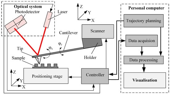
Figure 1. Simplified functional diagram of the AFM sensing, sample handling, and data processing system.
Typically, AFM consists of a few functional blocks: a positioning stage, a cantilever, a scanner, a controller, data processing, and visualization algorithms (Figure 1). The positioning stage ensures sample movement along three orthogonal axes; it consists of a set of precision drives and guides the positioning of the sample in the x, y, and z directions.
The complex sensor contains a cantilever, an optical system, and a scanner. Cantilever properties (i.e., stiffness and resonant frequency) depend on the design and material properties. Dynamic cantilever characteristics directly impact measurement result reliability since these characteristics limit the maximum possible scanning velocity and resolution [9]. Cantilever tip geometry determines the AFM imaging accuracy and resolution and influences the excitation of the cantilever [10].
The cantilever deflection is usually measured by an optical system consisting of a laser source and position-sensitive photodiode matrix [11]. The laser beam reflects from the upper surface of the cantilever and falls onto the active area of the photodiode matrix. The cantilever deflection is obtained from the position of the reflected laser spot. The reflection provides z-axis feedback to the controller. The z-axis deflection error signal and the tip coordinates are also transferred to the data acquisition and processing software to produce a three-dimensional image of the sample surface.
Cantilever deflection can also be measured by nonoptical methods based on capacitive, piezoelectric, or piezoresistive phenomena [12][13][14][15][16]. The deflection sampling rates generally are much higher than the settling time of the scanner [11]. Increasing the imaging speed, resolution, or both usually means increasing the sampling rate.
Before imaging, a few scanning parameters must be chosen: the size of the field of view, the scanning mode and speed, and the number of lines and points in each line. All these parameters will affect the overall image acquisition duration and future image resolution (Figure 2). The most popular imaging strategy is to start from a sparse, large field-of-view image, possibly interpolated by AI-enabled algorithms [17]. After that, the smaller region of interest is selected for high-resolution imaging. The software creates the image from sampled data points using various filters and interpolation algorithms [18]. Reconstruction-based imaging techniques and “Compressive sensing” theory can be used to minimize the number of required data points and, at the same time, to ensure a high resolution of the final image [19].
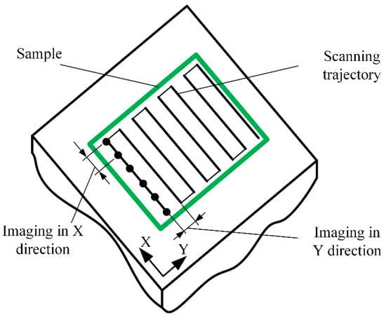
Figure 2. Schematic representation of the imaging process.
Optimization of the scanning parameters is one of the paths for increased AFM performance. Usually, the optimization strategy is subject to AFM operator experience and skills, and the optimization algorithm is based on the database [20] or a mathematical model [21], taking known data, such as the expected geometrical shape and material properties of a sample and the probe geometry, and calculating optimal scanning parameters to produce the required resolution of the image within an adequate time and with a minimum of image artifacts [22].
2. AFM Operating Modes
Depending on the interaction between the probe and the sample surface, three main AFM operating modes can be distinguished: contact mode, noncontact mode, and dynamic contact (tapping) mode [23][24]. The Van der Waals force mainly characterizes the probe and sample surface interaction. The intensity and direction of this force strongly depend on the distance between the probe and the sample surface (Figure 3).
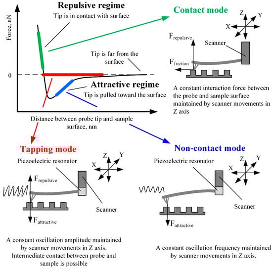
Figure 3. AFM working modes in respect of Van der Waals force.
The contact mode of AFM is based on scanning the surface in repulsive force mode by keeping a constant 1–2 Å distance from the sample surface. In this scanning mode, cantilever stiffness is essential since it directly impacts the cantilever’s deflection amplitude. Therefore, cantilevers of lower stiffness enable the imaging of surfaces with smaller feature sizes since the higher deflection of softer cantilevers produces a more significant error signal. On the contrary, if the cantilever is stiff and the sample surface features are small, the error signal can be too small to be sensed. The advantage of the contact mode is that a thin layer of water, which is always present on the surfaces of solid samples at standard conditions, has a minor influence on the measurement results. Therefore, due to the strong surface forces, the probe is attracted to the sample surface and “pierces” the water layer [25]. The contact mode also enables the measurement of friction, conductivity, elasticity, and other material properties. Moreover, the contact mode provides a higher resolution and scanning speed than different modes and enables the examination of surfaces with a broader range of features [12][25].
The speed limit is the main disadvantage of the contact mode. The low resonant frequency of soft cantilevers is the cause. During the scanning process, the sample surface structure causes kinematically excited oscillations of the cantilever. The frequency of these oscillations depends on the scanning speed. When the cantilever’s excitation frequency approaches its resonant frequency, the contact between the probe and the sample becomes unstable, making scanning results inaccurate [26]. Another disadvantage of the contact mode is that it is unsuitable for soft materials because the probe can damage soft biological materials and polymers. While scanning inhomogeneous materials, surface forces can have uneven magnitudes, lowering the reliability of the resulting topography image [27][28][29][30].
When the cantilever tip is near the surface of interest, an attractive Van der Waals force occurs between the tip and the surface. Scanning at the distance of attractive force is called noncontact mode, and it is mainly used for the analysis of soft (biological and organic) materials. In this mode, a special piezoelectric resonator mounted on the AFM cantilever fixture place (Figure 3) kinematically excites the cantilever base, which causes the cantilever to vibrate at a frequency close to its resonant frequency. When the probe approaches the sample surface, the cantilever oscillations’ frequency decreases due to attractive forces. By analyzing the variation in cantilever oscillation frequency, it is possible to determine the surface topography, viscosity, friction, and probe–surface interacting force [23]. The noncontact scanning method is more sensitive to ambient conditions than the contact mode [23]. While operating in the noncontact mode, it is required to ensure that the layer of liquid on the sample surface is thinner than the surface forces activity range, otherwise the tip of the cantilever can seize in the liquid layer and touch the surface of the sample. Contact with the scanned surface distorts the measurement results and can damage the cantilever or the sample, especially at a high scanning speed. The abovementioned problems can be avoided in tapping (dynamic contact) mode [31].
The tapping mode lies between the contact and noncontact modes and has features of both. In this mode, the cantilever is kinematically excited by the piezoelectric resonator, similarly to in noncontact mode (Figure 3). The only difference is the excitation amplitude—it is about ten times higher than in noncontact mode and can reach up to 200 nm. When the probe approaches the surface of interest, the cantilever’s oscillation amplitude decreases due to the surface forces acting on the tip. Still, the tip can accidentally touch the sample surface. The feedback of the z-axis position of the AFM scanner is used to maintain the constant oscillation amplitude of the cantilever. The image is obtained by mapping the z-axis feedback signal, which corresponds to the variation of the tip–sample interaction force [32]. The main advantage of the tapping mode is a higher image resolution and accuracy than the noncontact mode. The tapping mode is more suitable for scanning softer materials than the contact mode and is applicable for researching delicate biological samples. The tapping mode’s main disadvantage is a lower scanning speed and accuracy than the contact mode.
It is essential to mention other scanning modes when AFM operates in the intermediate regime between repulsive and attractive forces: peak force tapping and phase imaging. The first enables precise control of probe–sample interaction at very low interaction forces [33]. Typical peak force tapping applications include high-resolution imaging of soft samples in a liquid environment and nanomechanical and electrical/electrochemical property measurements. The phase imaging mode monitors the phase difference between the excitation and response signals of the cantilever, while oscillation amplitude is maintained constant by the z-axis position feedback [34]. This scanning mode is used for samples with significant surface irregularities and enables simultaneous mapping of topography and other material properties, such as adhesion, elasticity, and viscoelasticity. Phase imaging mode created the background for many other AFM techniques, such as magnetic force microscopy (MFM), electric force microscopy (EFM), and scanning capacitance microscopy (SCM) [35]. Furthermore, recent advances in machine learning allow the characterization of probe–sample interactions from experimental data with sub-microsecond resolution and open new capabilities for visualizing dynamic biological processes [36]. The first algorithm was trained on standard AFM models and then showcased experimentally with a polymer blend of polystyrene (PS) and low-density polyethylene (LDPE) sample.
One of the prospective modes of AFM, which allows increasing imaging resolution, is multifrequency AFM, in which the cantilever is simultaneously excited/observed at two or more separate frequencies [37][38][39]. In bimodal AFM, the first two flexural cantilever modes are used.
3. AFM Imaging Speed Optimization and Performance Increase Methods
While scanner properties remain constant, imaging speed can be optimized by choosing the proper scan range in the x-axis direction, the number of scan lines, the spatial frequency of the sample surface, and the maximum possible phase delay in tracing the sample surface [40]. AFM performance can be improved by various approaches, as shown in Figure 4. There are three main performance improvement trends: improvements focused on enhancing cantilever characteristics and designs, implementations of different cantilever property modification methods, and modifications of scanners.
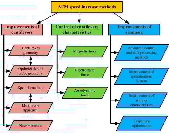
Figure 4. Classification of AFM scanning speed increase methods.
All the categories mentioned above contain several subcategories. The development of cantilevers focuses on the improvement of the following parameters: I—an increase in the resonant frequency of the cantilevers; II—optimization of the probe geometry; III—the application of various surface coatings for better reflectance or the production of specialized cantilevers whose deflection can be measured using the nonoptical method; IV—cantilever arrays suitable for multiprobe scanning; V—new materials for cantilever manufacturing.
The research focused on the in situ control, modification, and adjustment of cantilever characteristics is based on the hypothesis that instead of selecting and changing cantilevers for each case, it is possible to modify the dynamic characteristics of the cantilevers in situ, thus extending their field of application. This approach requires the application of external controllable force on a probe surface. This can be performed using magnetic, electrostatic, or aerodynamic force on the cantilever surface [26].
The AFM scanner improvements cover two general areas: software and hardware. Software improvement focuses on scanning trajectory optimization, the development of advanced control, and data processing methods. Hardware modernization concentrates on the enhancement of scanners and measurement systems.
References
- Vorburger, T.V.; Dagata, J.A.; Wilkening, G.; Iizuka, K.; Thwaite, E.G.; Lonardo, P. Industrial Uses of STM and AFM. CIRP Ann.-Manuf. Technol. 1997, 46, 597–620.
- Andriukonis, E.; Stirke, A.; Garbaras, A.; Mikoliunaite, L.; Ramanaviciene, A.; Remeikis, V.; Thornton, B.; Ramanavicius, A. Yeast-Assisted Synthesis of Polypyrrole: Quantification and Influence on the Mechanical Properties of the Cell Wall. Colloids Surfaces B Biointerfaces 2018, 164, 224–231.
- Tolenis, T.; Grinevičiūtė, L.; Kičas, S.; Buzelis, R. Enhancement of Optical Resistance in High Reflectivity Coatings Using Oblique Angle Deposition Method. In Proceedings of the Nanostructured Thin Films XI; International Society for Optics and Photonics, San Diego, CA, USA, 19–23 August 2018; Volume 10731, p. 107310.
- Gruskiene, R.; Krivorotova, T.; Staneviciene, R.; Ratautas, D.; Serviene, E.; Sereikaite, J. Preparation and Characterization of Iron Oxide Magnetic Nanoparticles Functionalized by Nisin. Colloids Surfaces B Biointerfaces 2018, 169, 126–134.
- Batiuskaite, D.; Bruzaite, I.; Snitka, V.; Ramanavicius, A. Assessment of TiO2 Nanoparticle Impact on Surface Morphology of Chinese Hamster Ovary Cells. Materials 2022, 15, 4570.
- Enrriques, A.E.; Howard, S.; Timsina, R.; Khadka, N.K.; Hoover, A.N.; Ray, A.E.; Ding, L.; Onwumelu, C.; Nordeng, S.; Mainali, L.; et al. Atomic Force Microscopy Cantilever-Based Nanoindentation: Mechanical Property Measurements at the Nanoscale in Air and Fluid. J. Vis. Exp. 2022, 190, e64497.
- el Rifai, K.; el Rifai, O.; Youcef-Toumi, K. Modeling and Control of AFM-Based Nano-Manipulation Systems. In Proceedings of the 2005 IEEE International Conference on Robotics and Automation, Barcelona, Spain, 18–22 April 2005; IEEE: New York, NY, USA, 2005; Volume 2005, pp. 157–162.
- Wang, Y.; Wang, J. Friction Determination by Atomic Force Microscopy in Field of Biochemical Science. Micromachines 2018, 9, 313.
- Hosaka, S.; Etoh, K.; Kikukawa, a.; Koyanagi, H. Megahertz Silicon Atomic Force Microscopy (AFM) Cantilever and High-Speed Readout in AFM-Based Recording. J. Vac. Sci. Technol. B Microelectron. Nanom. Struct. 2000, 18, 94.
- Peña, B.; Adbel-Hafiz, M.; Cavasin, M.; Mestroni, L.; Sbaizero, O. Atomic Force Microscopy (AFM) Applications in Arrhythmogenic Cardiomyopathy. Int. J. Mol. Sci. 2022, 23, 3700.
- Russell-Pavier, F.S.; Picco, L.; Day, J.C.C.; Shatil, N.R.; Yacoot, A.; Payton, O.D. “Hi-Fi AFM”: High-Speed Contact Mode Atomic Force Microscopy with Optical Pickups. Meas. Sci. Technol. 2018, 29, 105902.
- Nishida, S.; Kobayashi, D.; Sakurada, T.; Nakazawa, T.; Hoshi, Y.; Kawakatsu, H. Photothermal Excitation and Laser Doppler Velocimetry of Higher Cantilever Vibration Modes for Dynamic Atomic Force Microscopy in Liquid. Rev. Sci. Instrum. 2008, 79, 123703.
- Rugar, D.; Mamin, H.J.; Guethner, P. Improved Fiber-Optic Interferometer for Atomic Force Microscopy. Appl. Phys. Lett. 1989, 55, 2588–2590.
- Göddenhenrich, T.; Lemke, H.; Hartmann, U.; Heiden, C. Force Microscope with Capacitive Displacement Detection. J. Vac. Sci. Technol. A Vac. Surf. Film. 1990, 8, 383–387.
- Giessibl, F.J.; Trafas, B.M. Piezoresistive Cantilevers Utilized for Scanning Tunneling and Scanning Force Microscope in Ultrahigh Vacuum. Rev. Sci. Instrum. 1994, 65, 1923–1929.
- Alunda, B.O.; Lee, Y.J. Review: Cantilever-Based Sensors for High Speed Atomic Force Microscopy. Sensors 2020, 20, 4784.
- Han, G.; Lv, L.; Yang, G.; Niu, Y. Super-Resolution AFM Imaging Based on Compressive Sensing. Appl. Surf. Sci. 2020, 508, 145231.
- Amyot, R.; Marchesi, A.; Franz, C.M.; Casuso, I.; Flechsig, H. Simulation Atomic Force Microscopy for Atomic Reconstruction of Biomolecular Structures from Resolution-Limited Experimental Images. PLoS Comput. Biol. 2022, 18, e1009970.
- Nan, R.; Sun, G.; Wang, Z.; Ren, X. Research on Image Reconstruction of Compressed Sensing Based on a Multi-Feature Residual Network. Sensors 2020, 20, 4202.
- Sajjadi, M.; Chahari, M.; Nejat Pishkenari, H. Imaging Performance of Trolling Mode Atomic Force Microscopy: Investigation of Effective Parameters. Arch. Appl. Mech. 2022, 92, 1551–1570.
- Carracedo-Cosme, J.; Romero-Muñiz, C.; Pou, P.; Pérez, R. QUAM-AFM: A Free Database for Molecular Identification by Atomic Force Microscopy. J. Chem. Inf. Model. 2022, 62, 1214–1223.
- Morkvenaite-Vilkonciene, I.; Virzonis, D.; Dzedzickis, A.; Bucinskas, V.; Rozene, J.; Vilkoncius, R.; Vaiciulis, D.; Ramanaviciene, A.; Ramanavicius, A. The Improvement of the Accuracy of Electromagnetic Actuator Based Atomic Force Microscope Operating in Contact Mode and the Development of a New Methodology for the Estimation of Control Parameters and the Achievement of Superior Image Quality. Sens. Actuators A Phys. 2019, 287, 168–176.
- Yang, C.W.; Hwang, I.S.; Chen, Y.F.; Chang, C.S.; Tsai, D.P. Imaging of Soft Matter with Tapping-Mode Atomic Force Microscopy and Non-Contact-Mode Atomic Force Microscopy. Nanotechnology 2007, 18, 084009.
- Tello, M.; García, R. Nano-Oxidation of Silicon Surfaces: Comparison of Noncontact and Contact Atomic-Force Microscopy Methods. Appl. Phys. Lett. 2001, 79, 424–426.
- Butt, H.-J.; Cappella, B.; Kappl, M. Force Measurements with the Atomic Force Microscope: Technique, Interpretation and Applications. Surf. Sci. Rep. 2005, 59, 1–152.
- Dzedzickis, A.; Bucinskas, V.; Viržonis, D.; Sesok, N.; Ulcinas, A.; Iljin, I.; Sutinys, E.; Petkevicius, S.; Gargasas, J.; Morkvenaite-Vilkonciene, I.; et al. Modification of the AFM Sensor by a Precisely Regulated Air Stream to Increase Imaging Speed and Accuracy in the Contact Mode. Sensors 2018, 18, 2694.
- Magonov, S.N.; Whangbo, M. Surface Analysis with STM and AFM; Wiley: Hoboken, NJ, USA, 1995; ISBN 9783527293131.
- Zakaria, N.S.; Aziz, A.A. Effect of Medium on Interaction Forces between Atomic Force Microscopy (AFM) Tip and Gold Nanoparticle. J. Phys. Conf. Ser. 2018, 1083, 012035.
- Lei, H.; Cheng, N.; Zhao, J. Interaction between Membrane and Organic Compounds Studied by Atomic Force Microscopy with a Tip Modification. J. Memb. Sci. 2018, 556, 178–184.
- Agmon, L.; Shahar, I.; Yosufov, D.; Pimentel, C.; Pina, C.M.; Gnecco, E.; Berkovich, R. Estimation of Interaction Energy and Contact Stiffness in Atomic-Scale Sliding on a Model Sodium Chloride Surface in Ethanol. Sci. Rep. 2018, 8, 4681.
- Zhong, Q.; Inniss, D.; Kjoller, K.; Elings, V.B. Fractured Polymer/Silica Fiber Surface Studied by Tapping Mode Atomic Force Microscopy. Surf. Sci. 1993, 290, L688–L692.
- Gross, L.; Mohn, F.; Moll, N.; Liljeroth, P.; Meyer, G. The Chemical Structure of a Molecule Resolved by Atomic Force Microscopy. Science 2009, 325, 1110–1114.
- Xu, K.; Sun, W.; Shao, Y.; Wei, F.; Zhang, X.; Wang, W.; Li, P. Recent Development of PeakForce Tapping Mode Atomic Force Microscopy and Its Applications on Nanoscience. Nanotechnol. Rev. 2018, 7, 605–621.
- García, R. Dynamic Atomic Force Microscopy Methods. Surf. Sci. Rep. 2002, 47, 197–301.
- PhaseImaging Mode—Imaging Modes of AFM; Bruker: Billerica, MA, USA.
- Chandrashekar, A.; Belardinelli, P.; Bessa, M.A.; Staufer, U.; Alijani, F. Quantifying Nanoscale Forces Using Machine Learning in Dynamic Atomic Force Microscopy. Nanoscale Adv. 2022, 4, 2134–2143.
- Kiracofe, D.; Raman, A.; Yablon, D. Multiple Regimes of Operation in Bimodal AFM: Understanding the Energy of Cantilever Eigenmodes. Beilstein J. Nanotechnol. 2013, 4, 385–393.
- Damircheli, M.; Jung, U.; Wagner, R. The Effect of Sample Viscoelastic Properties and Cantilever Amplitudes on Maximum Repulsive Force, Indentation, and Energy Dissipation in Bimodal AFM. Phys. Scr. 2023, 98, 035708.
- Solares, S.D.; Chawla, G. Frequency Response of Higher Cantilever Eigenmodes in Bimodal and Trimodal Tapping Mode Atomic Force Microscopy. Meas. Sci. Technol. 2010, 21, 125502.
- Ando, T. High-Speed AFM Imaging. Curr. Opin. Struct. Biol. 2014, 28, 63–68.
More
Information
Subjects:
Engineering, Mechanical
Contributors
MDPI registered users' name will be linked to their SciProfiles pages. To register with us, please refer to https://encyclopedia.pub/register
:
View Times:
660
Revisions:
2 times
(View History)
Update Date:
11 Oct 2023
Table of Contents


Notice
You are not a member of the advisory board for this topic. If you want to update advisory board member profile, please contact office@encyclopedia.pub.
OK
Confirm
Only members of the Encyclopedia advisory board for this topic are allowed to note entries. Would you like to become an advisory board member of the Encyclopedia?
Yes
No
${ textCharacter }/${ maxCharacter }
Submit
Cancel
Back
Comments
${ item }
|
${ item.createdUser.fullName }
${ item.createdAt }
${ item.vote }
${ item.reply }
Delete
${ reply.createdUser.fullName }
${ reply.createdAt }
${ reply.vote }
Delete
There is no reply to this comment~
${ item.replyTextCharacter }/${ item.replyMaxCharacter }
Submit
Cancel
More
No more~
There is no comment~
${ textCharacter }/${ maxCharacter }
Submit
Cancel
${ selectedItem.replyTextCharacter }/${ selectedItem.replyMaxCharacter }
Submit
Cancel
Confirm
Are you sure to Delete?
Yes
No