Since 2011, there has been an international effort to evaluate the behavior of newer fuel rod materials for the retrofitting of existing light water reactors (LWR). These materials include concepts for the cladding of the fuel and for the fuel itself. The materials can be broadly categorized into evolutionary or improved existing materials and revolutionary or innovative materials. The purpose of the newer materials or accident-tolerant fuels (ATF) is to make the LWRs more resistant to loss-of-coolant accidents and thus increase their operation safety. The benefits and detriments of the three main concepts for the cladding are discussed.
1. Introduction
Since the 1940s, it has been known that if the temperature of the fuel rods in contact with water increases above 450 °C, the zirconium of the cladding would start oxidizing rapidly following an exothermic reaction [1][2][3]. Despite its narrow margin of temperature tolerance, Zr alloys (Table 1) have been used successfully by commercial nuclear power plants since the 1960s. Initially, the main alloying element for Zr alloys was less than 2% of Tin (Sn), but since the 1990s, Zr alloys containing a similar amount of Niobium (Nb) have been developed and implemented in the nuclear power stations worldwide (Table 1) [4]. The early Zr alloys had several environmental degradation issues with respect to both fuel cladding and BWR channels. The main degradation issues of Zr alloys in contact with the coolant were associated with general oxidation, nodular corrosion, galvanic corrosion, shadow corrosion, crud induced localized corrosion, hydriding, debris fretting, etc. [3][4][5]. The corrosion mechanisms of the Zr alloys were driven not only by the composition and microstructure of the used Zr alloys but also by poorly controlled water chemistry. Eventually, by cleaning the water of corrosion products (e.g., iron), adding hydrogen, zinc, and noble metal, most of corrosion degradation problems were understood and gradually retired. The only remaining major failure of Zr-clad fuel rods under LWR normal operation conditions is debris fretting [6][7]. Fretting is a process by which a foreign material (such as a stainless steel wire) repetitively touches the external surface of the cladding, causing its eventual perforation and allowing the coolant to enter into contact with the fuel and fission gases. Other failures issues, such as cracking from inside the cladding due to the accumulation of iodine, are now rare [4][5].
Table 1. Zr-based alloys used for fuel cladding.
| Alloy |
Nominal Composition in Mass Percent |
| Zircaloy-2 R60802 |
Zr + 1.2/1.7Sn + 0.07/0.20Fe + 0.05/0.15Cr + 0.03/0.08Ni (Fe + Cr + Ni = 0.18–0.38) |
| Zircaloy-4 R60804 |
Zr + 1.2/1.7Sn + 0.18/0.24Fe + 0.07/0.13Cr
(Fe + Cr = 0.28–0.37) |
| ZIRLO |
Zr + 1Sn + 1Nb + 0.1Fe (Optimized Zirlo has 0.67Sn) |
| M5 |
Zr + 1Nb + 0.14O |
| E110 |
Zr + 1Nb |
| E635 |
Zr + 1.2Sn + 1Nb + 0.35Fe |
| Zr-2.5Nb R60904 |
Zr + 2.4/2.8Nb |
After the March 2011 Fukushima accident, where there was a large amount of hydrogen generated due to the fast oxidation of Zr components by water, the international nuclear materials community started to consider if more accident-tolerant materials could replace the well-known Zr alloys (
Table 1). As such, the field of accident-tolerant fuels (ATF)—which later evolved into advanced technology fuels (ATF)—was founded to focus more upon the new technology and less upon the accidents. The main initial attributes of the ATF materials were that they should be more robust than Zr alloys, have lower reactivity with steam, and generate less hydrogen and heat than Zr.
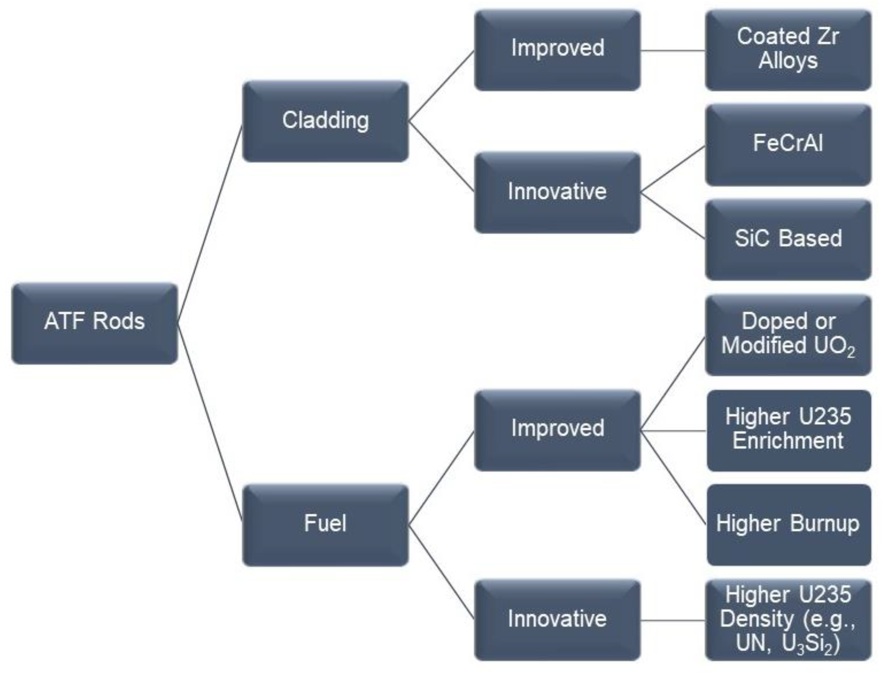
Figure 1 shows the main categories of accident-tolerant materials that have emerged for fuel rods
[1][3][8][9]. The proposed materials solutions can be classified as (1) evolutionary or improvement of the current fuel architecture; or (2) innovative or revolutionary solutions, which involve materials never used before in LWRs. The ATF materials not only refer to cladding but also to modifications for the fuel itself, such as doping the current uranium dioxide with chemicals to enhance its heat conductivity or to avoid a premature pellet fragmentation. Fuel producers are also investigating the use of other compounds of U for fuel such as silicide, carbide, and nitride. Other areas of associated studies involve increasing the concentration of U-235 in the pellets beyond 5% (higher enrichment) or extending the allowable burnup of the fuel beyond current regulatory restrictions of 62 GWd/MTU (
Figure 1)
[10]. Besides the fuel rods, other components that may need to be replaced in the reactor core using ATF candidates include BWR channel boxes and control rods.
Figure 1. Accident-tolerant materials under consideration for LWRs.
2. Improved and Innovative Materials for the Cladding
Figure 1 shows the three most common types of materials being investigated for the cladding of the fuel. The cladding materials are listed in the most likely chronological order in which they may be implemented (approved by regulatory authorities) in commercial power stations. This sequential order is directly related to our present knowledge on their likely performance in near 300 °C water under neutron irradiation. These newer LWR materials can be listed as follows: (1) coated Zr-based tubes (evolutionary or incremental gain, near term); (2) monolithic FeCrAl alloy tubes (revolutionary, metallic alloy, midterm); and (3) silicon carbide-based composites (revolutionary, a ceramic, longer-term implementation).
2.1. Coated Zr-Alloy, a Near-Term Concept (Evolutionary)
The coated Zr alloy ATF concept is considered evolutionary since the new product is a thin protective coating applied on top of Zr alloy rods already in use in LWRs
[1][11]. This concept does not remove the Zr alloys from the reactor; the coating just makes these Zr alloys more robust with respect to environmental resistance during operating conditions and during upset or design basis accident conditions. The protective coating thickness would be in the order of 20 µm or less over a tube wall, which is in the order of 0.6 mm thick; that is, the coating will represent approximately 3% of the total wall thickness. The two primary objectives of the ATF coating are to protect against debris fretting under normal operation conditions (~300 °C) and to protect against attack by steam up to 1000 °C in the case of a loss of coolant accident (LOCA). The coating could also provide protection against sliding wear by contact interaction with tube separation grids during bundle fabrication; the coating could decrease the propensity towards ballooning by the Zr alloy substrate; and in the case of a burst, the coating could reduce the opening gap for fuel release and dispersion into the coolant. Another objective of the coating would be to minimize hydrogen entrance into the Zr alloy cladding wall, especially for extended burnups in the reactor core. This is possible since the coating would offer lower corrosion rates that the Zr alloy (thus generating less hydrogen) and because the coating itself could be a barrier to atomic hydrogen diffusion into the substrate.
All three LWR fuel vendors in the USA are currently working on developing coatings for the Zr alloy tubes. The coating characteristics may be different for PWR reactors than for BWR reactors since the environments are different. By its own architecture, a Zr alloy tubing with a coating has always been considered the most likely ATF concept to receive the earliest regulatory approval. For some fuel vendors, the coating developments for fuel rods started before March 2011—mainly to protect the rods against perforation via debris fretting both in PWRs and BWRs and against shadow corrosion at the grid locations in BWRs. The coating development projects were later incorporated under the ATF programs since it was found that the coating not only provided fretting resistance under normal operation conditions but also provided additional environmental protection compared to bare Zr alloy substrates.
Tang et al.
[12] summarized the state of the art in coatings developments for ATF applications, discussing the wide range of coatings that were investigated globally by materials scientists. The coatings or surface transformation processes were grouped by families, namely, (1) surface modification by ion implantation; (2) non-metallic coatings such as carbon and silica; (3) metallic coatings such as chromium and FeCrAl alloys; (4) ceramic coatings such as alumina, MAX phases, carbides, nitrides, etc.; and (5) multi-layers coatings, each layer having only a few microns in thickness
[12]. In general, for a coating to be viable for commercial fuel rods applications, it needs to be able to be applied economically on full-length cladding tubes (~5 m long) with the desirable architecture or composition, thickness, and microstructure
[11]. The coating needs to be applied on Zr alloys at relatively low temperatures (e.g., below 400 °C) in order to preserve the properties of the Zr alloy substrate. The coating cannot add large neutron penalty; it needs to have a comparable coefficient of thermal expansion to the substrate in order to maintain adherence during thermal cycles and not have chemical interactions with Zr such as the formation of lower-temperature eutectic compounds. The merits of coating deposition methods—including (a) physical vapor deposition (PVD); (b) cold spraying; (c) cathodic arc evaporation; (d) magnetron sputtering; (e) electroplating, etc.—were addressed
[12].
In 2018, the Nuclear Energy Agency (NEA) of the OECD released a report on the state-of-the-art ATF including the concept of coatings for Zr alloys
[11]. Two broad categories were identified by the NEA for the coatings being studied globally: (1) metallic coatings; (2) ceramic coatings. The following beneficial effects of coatings compared to bare Zr alloys were identified: (a) low neutronic penalty for coatings less than 20 µm thick; (b) similar mechanical behavior for the Zr alloy cladding if the coating is less than 20 µm thick; (c) higher resistance to environmental degradation both in water and steam for coated rods as compared to bare rods; (d) significant reduction to hydrogen pick up by the cladding; (e) increased wear resistance; (f) strengthening effect at higher temperatures with decreasing susceptibility to ballooning and creep
[11].
It is crucial to demonstrate that these Cr coatings would endure in actual normal-operation-conditions commercial reactors environments. Fuel vendors have partnered with reactor owners’ utilities to insert ATF-coated fueled elements into LWRs
[13][14]. It has been reported that fuel rods of M5 Zr alloy coated with Cr through an optimized PVD process performed well during exposures to two 18-month cycles during in-pile irradiation at the PWR Vogtle Unit 2 power plant
[13]. PWR coolants contain dissolved hydrogen gas, providing a reducing environment for the in-core metallic components such as the fuel rods. Pool-side inspections showed that the Cr coating provided significant reduction in oxidation kinetics in contact with the coolant in the reactor during normal operation conditions, leading to a reduction of hydrogen production and pick up by the cladding substrate
[13].
Cold-spray-Cr-coated fuel rods of Zr alloy Zirlo (
Table 1) were exposed to the Byron Unit 2 PWR environment for two cycles
[14]. This insertion was first executed in 2019, when sixteen Cr-coated lead test rods (LTR) were introduced into the reactor core. Pool side inspection showed that after two cycles in the reactor, the hard-cold-spray Cr coating avoided scratching during fuel manufacturing and provided corrosion resistance, suppression of hydrogen pickup, and no indication of crud accumulation
[14]. In parallel to the exposure in the Byron-2 nuclear power station, in June 2020, thirty-two cold-spray-Cr-coated lead test rods (LTR) were added to four 17 × 17 fuel bundles in peripheral positions at the Doel Unit 4 plant (Belgium) at the start of cycle 31
[15]. The enhanced visual inspection of the Cr-coated rods after Cycle 31 (in November 2021) showed clean surfaces, which were bright and uniform in their length.
2.2. Monolithic FeCrAl, a Mid-Term Concept (Innovative or Revolutionary)
The second ATF cladding concept in
Figure 1 is a monolithic tube of iron–chromium–aluminum (FeCrAl) alloy. This concept is innovative since it implies the radical exchange of one alloy for another non Zr-based alloy and because the ferritic FeCrAl alloy system has never been used in LWRs before. Since the outer diameter (OD) of the newer alloy would be the same as the current Zr alloy, the coolable surfaces and thermal hydraulic conditions will practically remain the same. The idea of a steel-like alloy for cladding is not completely new since in the early 1960s, some power reactors used cladding of 300 series austenitic stainless steels despite their higher neutron absorption cross section. As the price of Zr alloys became more affordable for the industry, and due to in-service cases of stress corrosion cracking at the welds of the stainless steel clad rods, the idea of an austenitic stainless steel for the cladding of the fuel was eventually abandoned
[4].
2.2.1. Resistance to Oxidation in Steam at T > 1000 °C
FeCrAl alloys have been in use in the industry since the 1930s because of their strength and resistance to oxidation in air and steam. One alloy that has received attention recently regarding ATF application is APMT. These Fe-based alloys contain enough Cr and Al to make them resist oxidation up to their near melting point at approximately 1400–1500 °C. In these alloys, Cr and Al act synergistically; Cr provides protection to approximately 1000 °C, and above this temperature, the protection is given by aluminum oxide
[1][16][17][18][19]. Pint et al.
[16] exposed coupons of several alloys to a 3.4 bar of 100% steam for 8 h from 800 °C to 1350 °C and determined the mass change of the coupons. At 1000 °C, the Zircaloy-2 coupon had a mass gain of 48 mg/cm
2, while the mass gain for APMT was less than 0.5 mg/cm
2. The high Cr (>25%Cr) ferritic alloys without aluminum (such as Fe29Cr4Mo) showed substantial degradation above 1200 °C, showing that Cr alone cannot protect the alloy in steam
[16]. For example, at 1200 °C, the mass change for 29%Cr AL29-4C was 4 mg/cm
2, while for APMT, the mass change was less than 0.5 mg/cm
2 due to the formation of a solid-state alumina layer which is a diffusion barrier for oxygen from the environment
[16].
Rebak et al.
[20] exposed coupons to APMT and C26M for 2 h and 4 h to 100% steam and to laboratory air from 800 to 1300 °C. They reported that both alloys had similar oxidation resistance in both environments, but the dependence of oxidation with temperature was different for air and steam. In the lower temperature range, the mass gain due to oxidation was faster in steam; but in the higher temperature range, the oxidation was faster in air
[20].
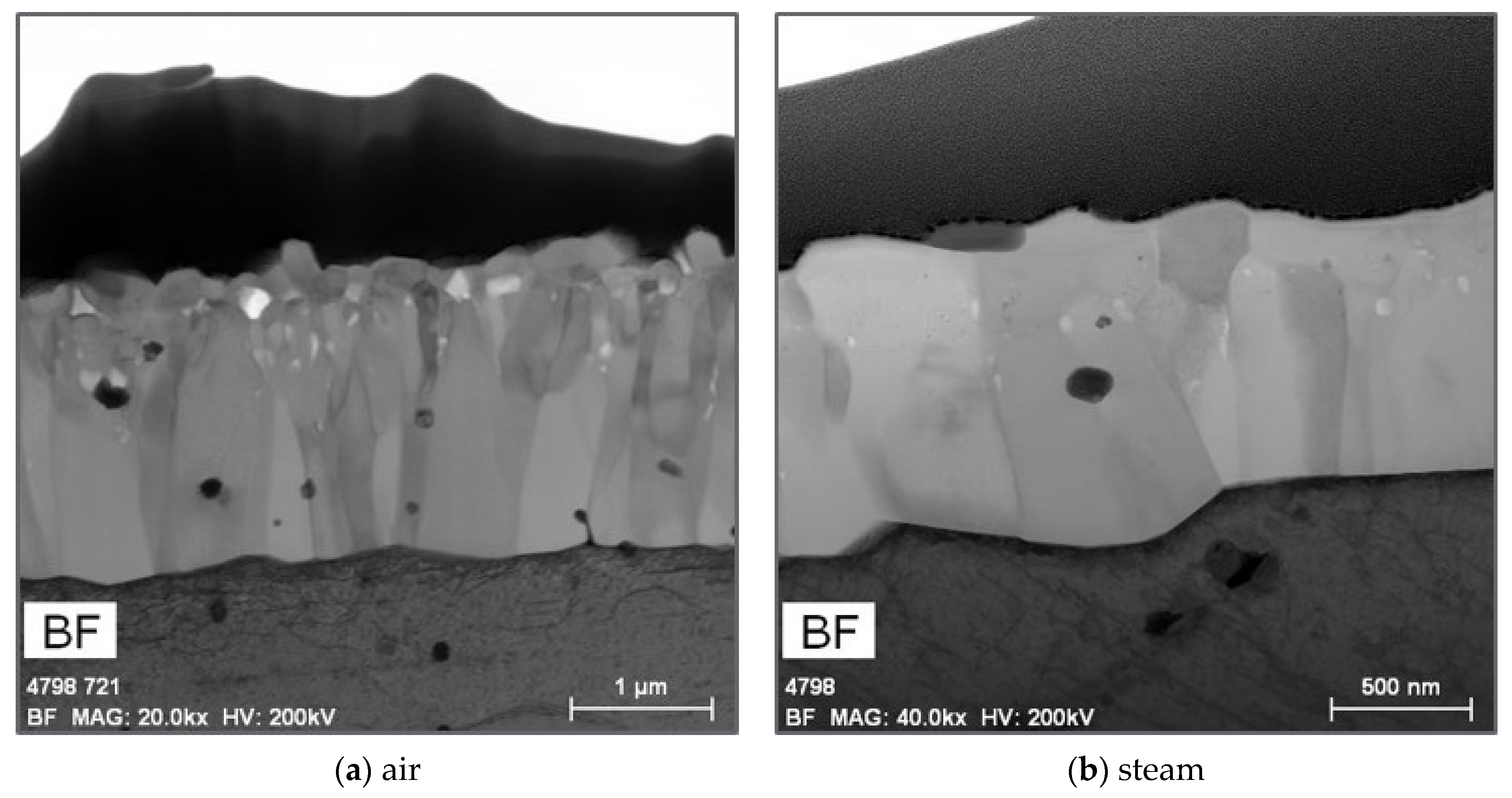
Figure 2 shows that the resistance to oxidation of APMT was provided by a thin—and highly adherent to the substrate alpha—alumina film.
Figure 2a shows that the alumina film in air was approximately 2.5 µm thick and it was columnar near the substrate and had equiaxed grains in the outer surface.
Figure 2b shows that in steam, the film was approximately 2 µm thick and composed only of columnar grains; it is apparent that the external smaller grains (which are present in air) were removed by interaction with steam.
Figure 2. Alpha alumina film on the surface of APMT coupons exposed at 1200 °C for 4 h in (
a) air and (
b) steam
[20].
2.2.2. FeCrAl Alloys Are Resistant to Stress Corrosion Cracking from the Water and Fuel Side
It is difficult to address in detail all the attributes of the FeCrAl alloys for cladding applications. The outstanding mechanical properties of FeCrAl, such as APMT compared to Zircaloy-2, have been recently discussed elsewhere
[21]. The fact that APMT is much stronger than Zirc-2 at temperatures near 350 °C would allow for the reduction of the wall thickness of the APMT to 0.3 mm from the 0.6 mm currently used for Zr alloys. This reduction in wall thickness will compensate for the higher thermal neutron absorption of the FeCrAl alloys compared to Zircaloy. APMT and other FeCrAl alloys have excellent mechanical properties and creep resistance at temperatures in the order of 800 °C, which is more than double the temperature of the normal operation of the cladding. APMT and the newer generation of C26M cladding tubing are fabricated using powder metallurgy, which results in small grain sizes and high yield strength
[21]. APMT has small additions of other alloying elements, developing nanosized particles that further increase its strength
[22]. FeCrAl alloys also have a higher resistance to creep than Zircaloy-2, which is going to provide a delay to ballooning or rod burst, and in general, the lower creep rate will help maintain better dimensional stability in case of a design basis accident
[1][19].
Austenitic stainless steels are susceptible to stress corrosion cracking (SCC) in LWR environments
[23][24]. Ferritic stainless steels are less prone to SCC in LWR environments than their austenitic cousins
[25][26][27]. The resistance to cracking of ferritic stainless steels was also reported in supercritical pressurized water pertaining to Generation IV reactors
[28][29]. Not only ferritic Fe–Cr alloys are resistant to cracking; ferritic FeCrAl alloys such as APMT and C26M are also resistant to SCC in LWR environments, both under hydrogen and oxygen conditions
[26][30].
It has been known since the 1960s that Zr-based alloys may suffer from stress corrosion cracking from the fuel cavity due to the presence of the element Iodine (I), which is the result of fission reactions
[31]. The SCC promoted by iodine from the ID of the Zr alloy cladding tube is generally recognized as the result pellet–cladding interaction (PCI), which would impart tensile stresses to the internal diameter (ID) of the tube. The issue of cracking of the Zr alloy due to exposure to iodine is still being studied today even though plant rod failures related to this mechanism are rare. Since FeCrAl alloys are being investigated to replace Zr alloys as the cladding, it was important to examine if the new alloys would undergo cracking in the presence of fission products as well.
2.2.3. FeCrAl Alloys Undergo Uniform Passive Corrosion in Normal Operation Conditions
When designing corrosion control, it would be better to select a material that does not corrode. Since this is not likely, the second-best option is to select a material that would recede uniformly, incorporating corrosion allowance into the design. Localized corrosion such as pitting corrosion or intergranular attack are not desirable since they could be sites for stress concentration. The corrosion characteristics of Zr alloys in condensed water at near 300 °C has been studied for many decades. It is known that when Zr oxidizes in water, it develops an adherent ZrO
2 oxide on the surface via the inward diffusion of oxygen anions. This oxide may start spalling after a certain threshold oxide thickness (e.g., 50 to 100 µm) is achieved
[5][32].
Since 2013, many studies of corrosion of FeCrAl alloys have been conducted in out-of-pile simulated LWR conditions, such as pure water in the vicinity of 300 °C containing either oxygen or hydrogen dissolved gases. While Zr alloys show weight gain in both oxygen- and hydrogen-rich water, FeCrAl generally loses some mass in hydrogenated or reducing conditions and may gain mass in oxygenated or oxidizing conditions
[33][34][35][36]. This behavior is understandable since the corrosion potential of APMT, for example, increases more than 700 mV going from a hydrogen water chemistry to an oxygen water chemistry
[37]. The amount of mass loss or gain for FeCrAl will depend mostly on the amount of Cr in the alloy
[36]. In hydrogen atmospheres, the oxide film on the surface of the FeCrAl coupons consisted mainly of a thin layer of chromium oxide (Cr
2O
3), while in oxygen containing waters, the oxide consisted or a double layer, i.e., an external thicker layer with a mixture of iron and chromium oxides and an internal layer of nearly pure Cr
2O
3.
2.2.4. FeCrAl Alloys Are Resistant to Debris Fretting
Currently, the major fuel rod failure in operating LWRs is the perforation of the protective cladding due to fretting wear
[6][7]. Once the cladding is breached, the coolant may enter into contact with the fuel and the fission gases, allowing for radioactive elements to escape into the coolant. One of the main reasons (even before the events at Fukushima) that the nuclear materials industry was exploring the possibility to using coatings to protect Zr-based alloys cladding was because the hard coating would protect against fretting wear of the cladding. This fretting wear could be a result of grid-to-rod or by foreign debris. If a monolithic FeCrAl alloy cladding is used in place of the current Zr-based alloy cladding, it may seem intuitive, based on their relative mechanical properties in the vicinity of 300 °C, that the FeCrAl would offer better wear resistance than the Zr alloys
[18][38].
The relative wear resistance of APMT and Zircaloy-2 against the nickel-based alloy X-750 was assessed in moist air at 300 °C
[39]. In this test, discs or pucks of the alloys were used. While the X-750 puck was static, the pucks of either APMT or Zircaloy-2 were rotating against the X-750 puck at 50 rpm for a total testing time of 20 h. The wear damage was evaluated by characterizing surface wear scars. Results showed that there was considerable Zircaloy-2 material transported to the X-750 puck.
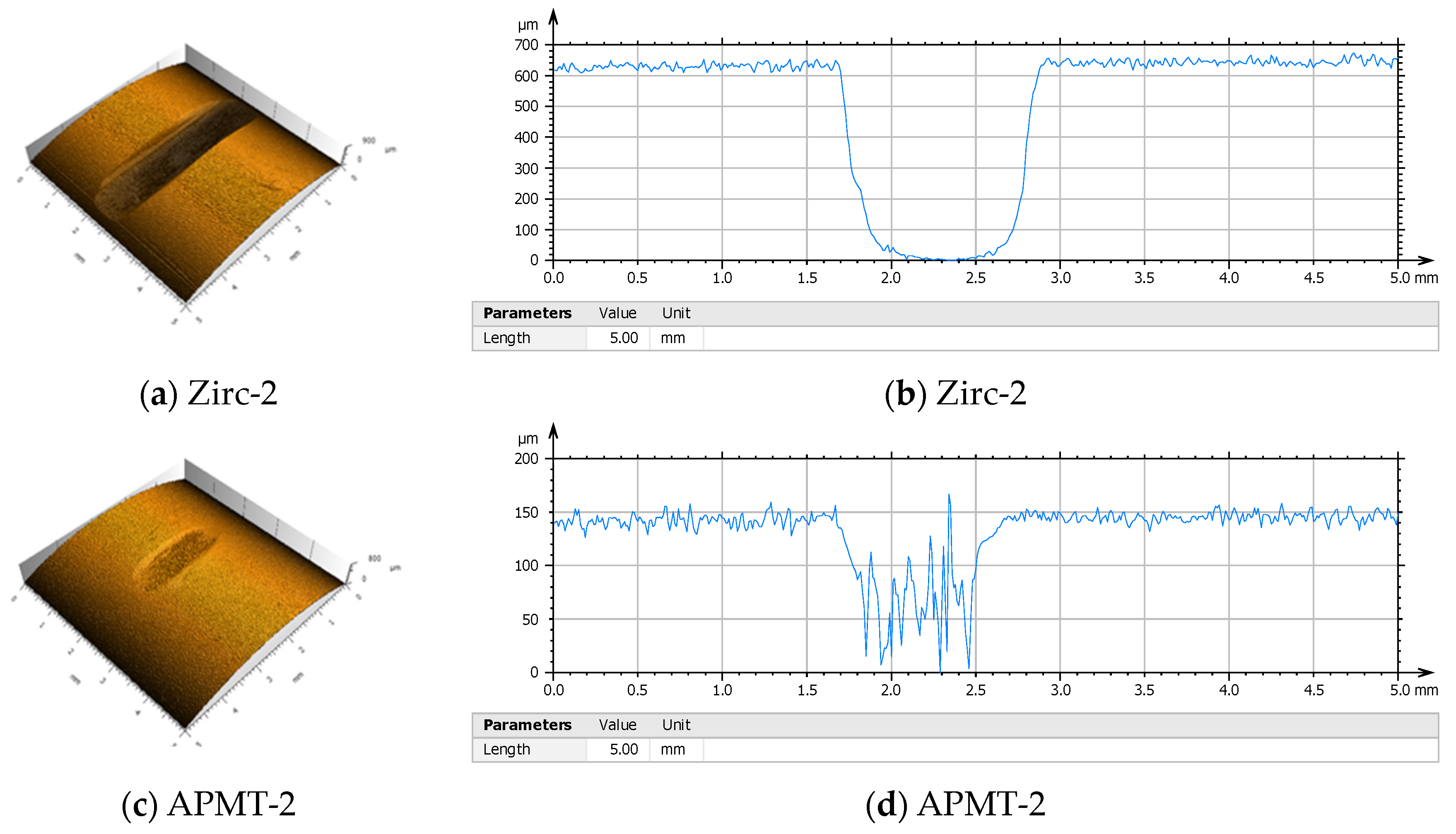
Figure 3 shows the results from a wear test conducted for two weeks in an autoclave with BWR NWC conditions or pure water at 288 °C containing 1 ppm dissolved oxygen
[3]. In this test, a protruding 0.031-inch (0.79 mm) diameter spring wire of type 304SS was fixed on a rotating central shaft, and as the central shaft rotated, the wire touched repeatedly four vertical cladding tubes. These tubes were at 90° from each other. After 14 days of testing, the wear mark or groove on the Zirc-2 tube was approximately 600 µm deep (through the wall) and with a width of more than 1 mm (
Figure 3a,b). In this side-by-side test, the groove mark on the APMT-2 tube was less than 100 µm deep and less than 1 mm wide (
Figure 3c,d). This test, performed in simulated BWR environments, shows the superior resistance of APMT cladding to Zircaloy-2 cladding.
Figure 3. Relative wear rate of APMT and Zircaloy-2 after a test wherein a rotating wire of 304SS would repetitively touch the tubes. (
a,
b) A 600 µm deep wear groove formed on the Zirc-2 cladding after two weeks testing in 288 °C water. (
c,
d) A shallower 100 µm deep groove formed on the APMT tube after two weeks in 288 °C water
[3].
2.2.5. Irradiation Campaigns and Deployment
Another concern regarding the use of ferritic alloys containing Cr is the embrittlement effect due to alpha prime formation. Thermal aging studies have shown that there is a reduction in ductility due to alpha prime formation in APMT; however, there is a remaining acceptable ductility in the material of approximately 10%
[40]. The effects of neutron irradiation on alpha prime formation and overall radiation damage such as swelling need to be studied in more detail
[18].
APMT rodlets were neutron irradiated at the Idaho National Laboratory (INL) Advanced Test Reactor (ATR) in two campaigns, namely, ATF-1 and ATF-2. In the first campaign, the rodlet ATF-8 (or G03) containing GNF UO
2 fuel was dry irradiated to 18.3 GWd/MTU. Post-irradiation examinations (PIE) showed no significant changes in the hardness of APMT cladding due to the neutron irradiation
[41][42].
Fueled and non-fueled articles of both APMT and C26M were also inserted into two commercial reactors: (a) the Hatch Power Plant #1 in February 2018; (b) the Clinton Power Plant #1 in October 2019. The IronClad articles survived the residence in the reactor and were transported to cooling pools.
2.3. Silicon Carbide-Based Cladding—A Long Term Concept (Revolutionary)
The third ATF cladding concept in
Figure 1 is a cladding tube based on a composite of the ceramic compound silicon carbide (SiC). The SiC-based concept is truly revolutionary since it is not a coating on an existing product and it is not a monolithic alloy like a stainless steel. The basic architecture of the ceramic cladding would be a tube made of SiC fibers and then impregnated with a SiC matrix. This is necessary since the SiC itself is brittle and it needs the strong fibers to reinforce it. The fracture toughness of the composite is higher than the one for the matrix by itself
[43]. As for FeCrAl, the idea of using SiC for nuclear applications is not new since it was explored before the ATF concepts were born in 2011
[1][43][44]. The use of a SiC composite may allow the cladding to stand temperatures up to near 1700 °C during accident conditions
[13].
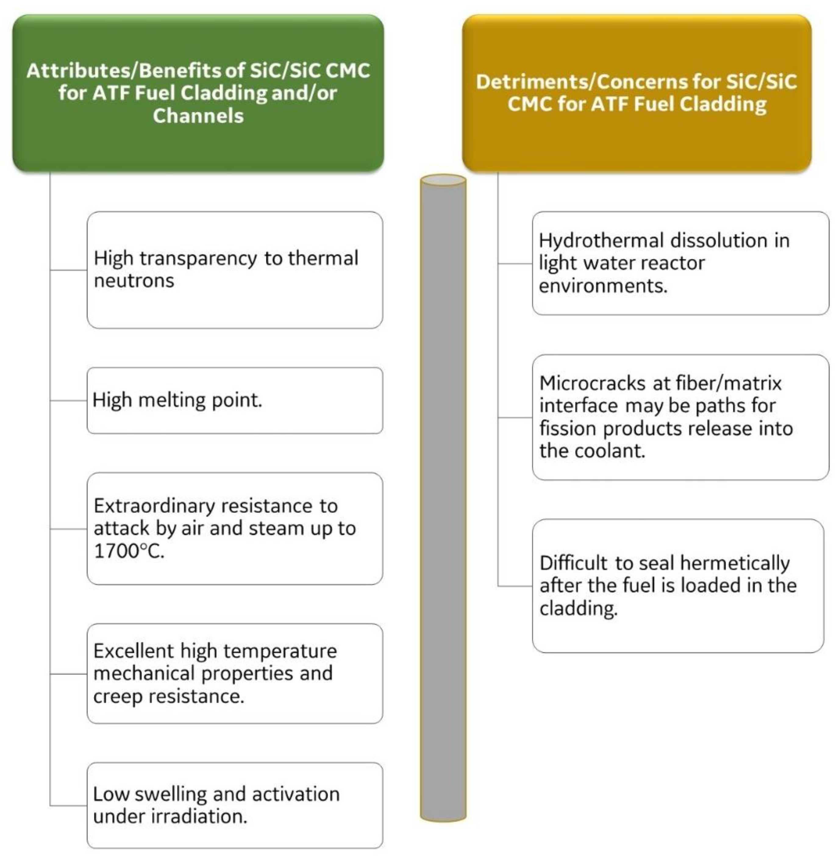
Figure 4 shows the attributes or benefits and detriments or concerns regarding the use of a SiC composite for an ATF cladding. The main attributes of SiC for cladding applications are their transparency to neutrons, their resistance to neutron irradiation damage, and their outstanding resistance to attack by steam. The slow reaction with steam will not produce ignitable hydrogen gas, which is one of the main concerns that led to the ATF program
[1][13][22][43][45]. Coupons of chemical-vapor-deposited (CVD) SiC were tested from 2 h to 48 h in 100% steam and in a mixture of hydrogen gas with 50% of H
2O at temperatures ranging from 800 °C to 1350 °C
[16][22]. For the CVD SiC coupons, the mass change was almost undetectable from 800 °C to 1200 °C, and at 1300–1350 °C, it showed a mass gain of 2 mg/cm
2 [16]. The silica (SiO
2) layer on top of the coupon tested for 8 h at 1350 °C was approximately 5 µm thick. The thickness of the silica layer changed depending on the gas velocity, since the oxide volatilization as the compound Si(OH)
4 changes with the gas velocity
[16]. A large variety of materials were tested during a screening process in a stream of gas containing 50% H
2O in argon at 1 bar pressure and at 1200 °C using thermal gravimetric analysis (TGA). The lowest oxidation rate was for CVD SiC and the second lowest was for APMT
[16].
Figure 4. Benefits and detriments on the use of SiC composite for an ATF cladding application.
One of the major concerns of the use of SiC composite materials as ATF cladding is their instability in hot water
[1][44][46]. The corrosion performance of SiC composites in hot condensed water is a strong function of the fabrication route of the cladding and the exact environmental conditions
[43][44]. For LWR applications, the redox potential of the coolant would be an important factor in controlling the recession rate of SiC composites, since the presence of a few ppb of oxygen in the water can be an accelerating factor
[44].
2.4. How ATF Can Help Extending the Life of LWRs
Figure 5 shows a schematic representation of the barriers that exist between the toxic components in the fuel cavity (1) and the environment (6). For the radioactive elements in the fuel cavity to be released to the environment, they need to breach the tube or cladding (2), then the water (coolant) (3) in the reactor core, and the last two barriers of the metallic reactor pressure vessel wall (4) and the external cement barrier (5). This type of architecture is what the Nuclear Regulatory Commission calls “defense in depth.” In the case of the Fukushima scenario, the lack of water recirculation caused the zirconium alloy cladding tube (2) to react with the surrounded water or steam (v) to produce hydrogen gas and zirconium oxide according to the following:
Figure 5. Multiple barriers are built to reduce risk of toxic elements being released in the environment.
2.5. ATF Materials and the Fuel Cycle
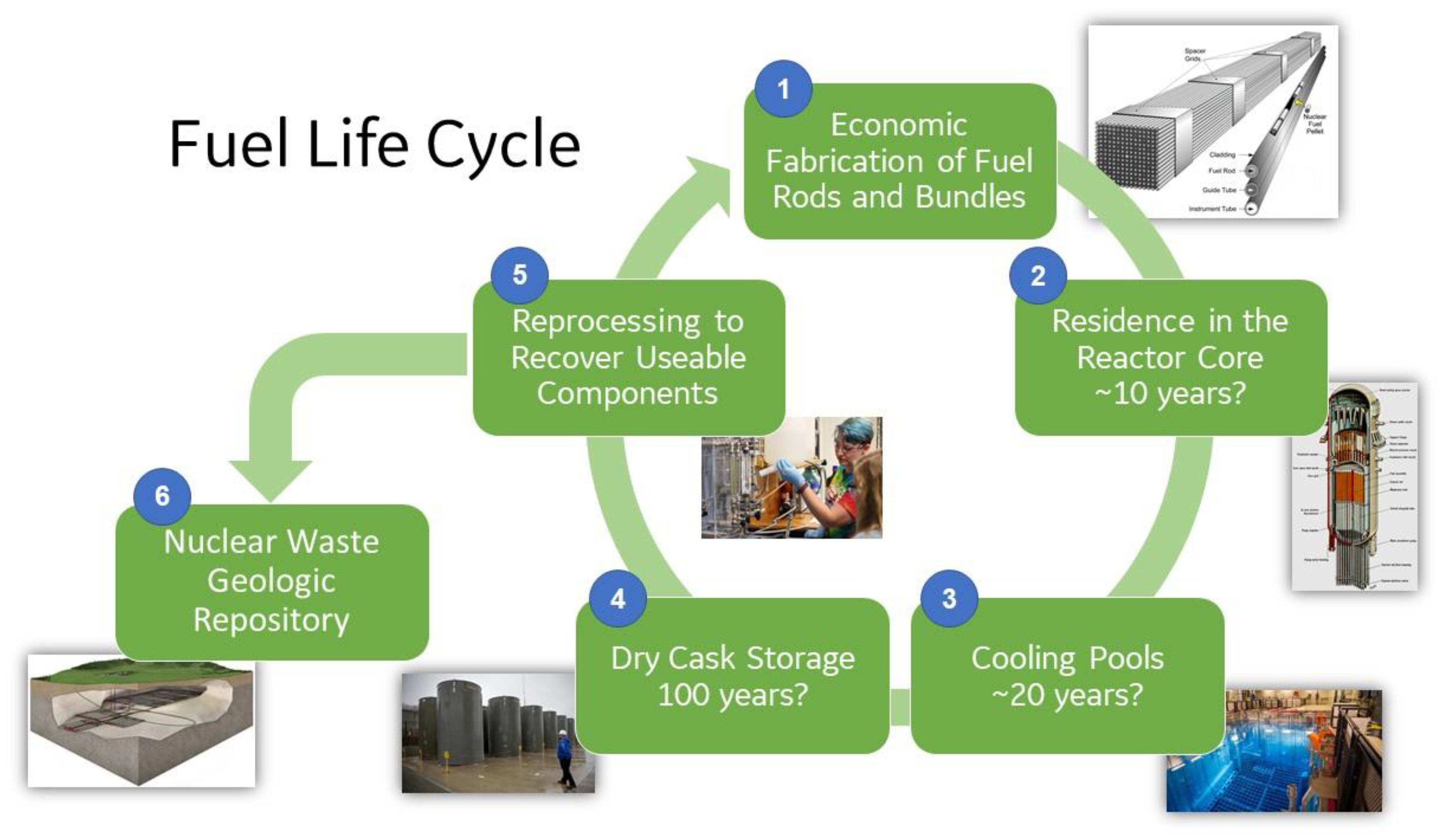
The modified and innovative ATF materials listed in Figure 1 have not yet been in the production of power in an LWR. Figure 6 shows an example of a fuel cycle from cradle to grave. The behavior of Zr-based alloys has been investigated in this entire cycle through the decades. However, the newer ATF materials such as FeCrAl still need to be evaluated. The reliable fabrication of fuel rods (Step 1 in Figure 6) from basic raw materials needs to be demonstrated. The manufacturing of slender seamless tubes of APMT was proven in an industrial setting, using powder metallurgy to HIP ingots, and later applying pilgering up to the final dimensions of 5 m long and 0.3 mm wall thickness. It was also proven that the end caps can be welded to the APMT tubes using pressure resistance welding (no melting). FeCrAl materials are inexpensive and existent tube fabrication plants can manufacture and weld the end caps to the tubes. The fuel rods with innovative materials then need to survive maybe 10 years under normal operation conditions in the reactor while in contact with ~300 °C water under irradiation (Step 2). APMT has been shown to have low recession rates both in oxygenated and hydrogenated water, and the presence of Zn decreases this corrosion even more. If there is a loss of coolant accident, the APMT rods need to resist oxidation and resist the generation of hydrogen gas while maintaining their geometry until the reactor is flooded again with fresh water. After three cycles in the reactor core, the bundles of the APMT rods need to be retrieved in one piece and transported to the cooling pools (Step 3). Residence in the cooling pools could take up to 20 years to allow for the short-lived toxic radionuclides to decay and thus reduce the heat in the rods. The water in the pools is generally at 60 °C, and its chemistry is carefully controlled. For passivating alloys such as APMT in the pool water, the general corrosion should be negligible. Electrochemical tests results showed that APMT was resistant to localized corrosion and that its passivation breakdown potential was higher than that of type 316SS. Step 4 in Figure 6 shows that after the cooling pools, the used fuel would go to dry cask storage, where it would remain for a longer time. In the dry casks, the heat of the bundles is removed by natural air convection, and the temperature of the bundles may never reach 100 °C.
Figure 6. Fuel cycle from manufacturing to used fuel disposition.
 +1 credit