Submitted Successfully!
To reward your contribution, here is a gift for you: A free trial for our video production service.
Thank you for your contribution! You can also upload a video entry or images related to this topic.
Version Summary Created by Modification Content Size Created at Operation
1 -- 2600 2023-08-02 12:32:15 |
2 format correction -3 word(s) 2597 2023-08-03 02:45:47 | |
3 format correction -4 word(s) 2593 2023-08-08 02:32:39 |

Video Upload Options

Do you have a full video?

Confirm

Are you sure to Delete?
Cite
If you have any further questions, please contact Encyclopedia Editorial Office.
Hiruta, Y.; Xie, C.; Shishido, H.; Kitahara, I. 3D Estimation Using an Omni-Camera and a Spherical-Mirror. Encyclopedia. Available online: https://encyclopedia.pub/entry/47550 (accessed on 05 May 2024).
Hiruta Y, Xie C, Shishido H, Kitahara I. 3D Estimation Using an Omni-Camera and a Spherical-Mirror. Encyclopedia. Available at: https://encyclopedia.pub/entry/47550. Accessed May 05, 2024.
Hiruta, Yuya, Chun Xie, Hidehiko Shishido, Itaru Kitahara. "3D Estimation Using an Omni-Camera and a Spherical-Mirror" Encyclopedia, https://encyclopedia.pub/entry/47550 (accessed May 05, 2024).
Hiruta, Y., Xie, C., Shishido, H., & Kitahara, I. (2023, August 02). 3D Estimation Using an Omni-Camera and a Spherical-Mirror. In Encyclopedia. https://encyclopedia.pub/entry/47550
Hiruta, Yuya, et al. "3D Estimation Using an Omni-Camera and a Spherical-Mirror." Encyclopedia. Web. 02 August, 2023.
3D Estimation Using an Omni-Camera and a Spherical-Mirror
Edit

There is a novel approach for estimating the 3D information of an observed scene utilizing a monocular image based on a catadioptric imaging system employing an omnidirectional camera and a spherical mirror. Researchers aim to develop a method that is independent of learning and makes it possible to capture a wide range of 3D information using a compact device.

3D estimation catadioptric imaging system omnidirectional camera spherical mirror

1. Introduction

The growing demand for 3D information in various fields, such as autonomous driving for understanding the traffic environment or providing a free viewpoint in sports events, has led to the rapid spread of technologies for acquiring and displaying 3D information. These technologies can be categorized into two main types: active sensing, which involves irradiating objects with light for measurement, and passive sensing, which utilizes cameras as light-receiving sensors. Active sensing methods, like LiDAR(Light Detection and Ranging) [1], offer direct 3D information but require additional light-emitting devices. Passive sensing methods, specifically cameras, become necessary to incorporate visual information, such as texture, into the measured 3D information. However, there are challenges related to the scale of observation systems, measurement range, and prior knowledge.

The widely-used Structure from Motion (SfM) technique [2] enables high-precision 3D reconstruction using multiple or moving cameras. However, this approach necessitates large-scale observation equipment and dynamic imaging. Researchers have explored estimating 3D information from single-shot images captured by a single camera to achieve compactness. Nonetheless, this leads to a limited observation range. This limitation can be overcome by utilizing omnidirectional cameras.

Deep learning-based 3D estimation from monocular omnidirectional images [3] has garnered attention. However, estimating 3D information for unknown objects poses difficulties due to the reliance on prior knowledge, specifically training data. Estimating the 3D shape of objects with insufficient training data, such as scenes containing rare objects, may decrease accuracy.

One method for obtaining alternative viewpoints in monocular images is through mirrors. A catadioptric system, commonly found in telescopes, consists of a mirror and lenses. When a camera is used as a lens in such a system, it is called a catadioptric imaging system. By employing a curved mirror, the catadioptric imaging system captures the light rays reflected on the mirror surface, enabling the observation of a wider scene than conventional cameras. However, most catadioptric imaging systems [4][5][6][7] have a fixed positional relationship between the mirror and the camera, limiting the observation range and degree of freedom. Agrawal et al. [8] proposed using multiple curved mirrors to estimate 3D information when the positional relationship in the catadioptric imaging system is not fixed. Thus, these require multiple mirrors [6][8] or imaging systems [5][7], resulting in compactness and single-shot imaging loss. Researchers propose a 3D estimation method for a catadioptric imaging system using a single curved mirror with an unknown 3D position. Thus, prior to estimating the 3D information of the observed scene, the method estimates the 3D position of the mirror by analyzing the mirror image region in the captured image. The objective is to estimate a wide range of 3D information from a monocular image captured using a compact device without relying on training data.

The proposed method is considered effective for dynamic tubular objects because its characteristic is that 3D information is estimated more effectively on the side of the system. For example, it can be applied to the estimation of 3D information from an endoscope, a medical device that takes images inside the body. Sagawa et al. [9] utilized an endoscope with an attachment for omnidirectional observation, allowing for wide-range observation inside the body. With a compact device, the proposed method makes it possible to estimate a broad spectrum of 3D information concerning the body, which undergoes temporal changes, from a single-shot image. In addition, since the positional relationship of the system is estimated from the captured images, the system does not require prior calibration, as is the case with stereo systems that use two camera sets, and is robust to external vibrations and long-term use. In stereo, the positional relationship of the camera sets at the calibration time can deviate, leading to decreased accuracy. In tunnel excavation, a vibration of the drill creates such a situation. Thus, this method is considered to be effective for tunnel excavation.

2. 3D Estimation Method Using an Omnidirectional Camera and a Spherical Mirror

The proposed 3D estimation process follows the flow shown in Figure 1. In this process, a known spherical mirror is assumed to be placed in the scene, and images of the mirror are captured using an omnidirectional camera.

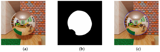
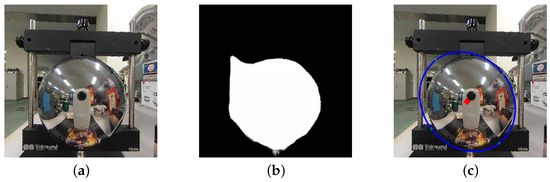
To estimate the 3D information in the catadioptric imaging system, the determination of the 3D position of the spherical mirror is crucial. This method estimates the mirror's position by analyzing the mirror image observed in the omnidirectional image. The mirror region is obtained by applying the mirror region segmentation network discussed to the omnidirectional image. An ellipse is fitted to the mirror region, and the 3D position of the spherical mirror is estimated based on the shape of the ellipse.

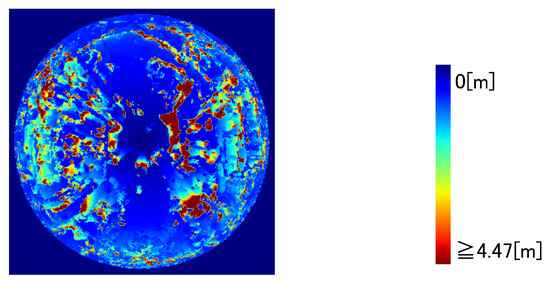
The 3D information of the captured scene is estimated using the estimated 3D position information of the spherical mirror. The process begins with backward projection, which determines the reflection points on the spherical mirror's surface and the incident light ray directions from the objects in the scene. Next, to obtain the 3D information observed from multiple viewpoints, the mirror image at each reflection point and the corresponding area in the omnidirectional image are searched. Stereo matching along the ray directions, estimated through backward projection, is performed to calculate the similarity of visibility. The 3D information with the highest similarity is selected. The similarity of visibility is computed using a color histogram, considering the distortion of the mirror image caused by the spherical shape. This process is applied to all pixels of the spherical mirror in the omnidirectional image.

By following this flow, the proposed method enables the estimation of 3D information in the scene captured by the catadioptric imaging system, leveraging the 3D position estimation of the spherical mirror and the analysis of the mirror reflections.

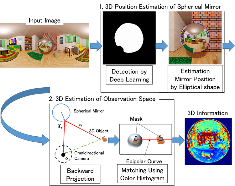
Figure 1. The Process of a 3D Estimation Based on a Catadioptric Imaging System with an Omnidirectional Camera and a Spherical Mirror: 1. Segmentation of the mirror image region in an omnidirectional image by network. Estimation of the 3D position of a spherical mirror from the shape of the mirror image. 2. Estimation of the 3D information of the shooting scene based on the 3D position of the spherical mirror. Searching for the omnidirectional image part corresponding to the mirror image using the incident light rays from the object obtained by the 3D position information of the spherical mirror, using stereo matching.

3. Simulation

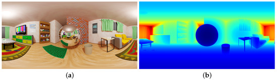
3.1. Simulation with CG Model of a Room

The simulation used a CG model of a room to test the proposed method. A spherical mirror with a 0.5 [m] radius was placed 1 [m] from the camera in the CG environment. The omnidirectional image captured in the experiment and its corresponding ground truth image are shown in Figure 2a,b, respectively. Both images have a resolution of 4096 [pixels] × 2048 [pixels].
Figure 2. Input Images in Comparison Simulation in Room Model: (a) The shooting omnidirectional image. The mirror image is in the center. (b) The GT image of the shooting image.
The first step of the simulation was to estimate the position of the spherical mirror. The mirror image region in Figure 2a is shown in Figure 3a, and the segmented mirror region is displayed in Figure 3b. An elliptical shape was estimated based on the segmented mirror region, as shown in Figure 3c. The result of the spherical mirror position estimation was 1.03358 [m].
Figure 3. Estimation Result Images of Position of Spherical Mirror: (a) The image of the mirror image region from the shooting image. (b) The image of the segmented mirror region from the image of (a). (c) The image of the estimated elliptical shape based on (b).
Next, the 3D information estimation results are presented in Figure 4a. The estimation map in Figure 4a visualizes the results by linearly changing the hue, where blue represents the smallest values and red represents the largest values. The difference between the ground truth values and the estimated results at each pixel is shown in Figure 4b. The error map in Figure 4b visualizes the differences by linearly varying the brightness.
Figure 4. Distance and error estimation from the simulated scene: (a) The estimation map by the proposed method. The map is visualized by changing the hue linearly. (b) The error map. The map is visualized by varying the brightness linearly. The map is obtained by the difference between the ground truth at each pixel and the result estimated by the proposed method. The errors are larger at the edge and the center of the mirror image region.
The evaluation metric used for assessment is the Mean Absolute Error (MAE), calculated by summing all the pixels’ errors and dividing by the total number of pixels. The proposed method was evaluated for all points in the mirror image. In this evaluation, the estimated depth represents the distance between the mirror surface and the camera center for the directly imaged parts of the image that correspond to the mirror surface. At the same time, the ground truth values are the corresponding distances. The error is calculated as the sum of the absolute differences (Sum of Absolute Differences—SAD) between the estimated and the ground truth depths. The MAE value obtained from the proposed method on this evaluation index was 1.15853 [m].

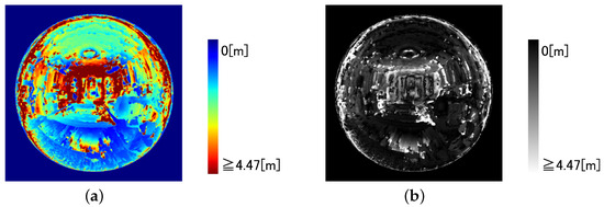
3.2. Discussion of Room Model Simulation

Figure 4b indicates that the proposed method achieves minor errors in many locations within the mirror image, suggesting that estimating the 3D information with reasonable accuracy is possible. However, there are two main reasons for the lower accuracy observed in some cases.
One reason is the difference in appearance between different viewpoints. The direct image captured by the omnidirectional camera and the mirror image reflected by the spherical mirror makes it possible to have different appearances from different positions. These differences correspond to the motion disparity of a camera in stereo, etc. For example, if researchers focus on the trash can in the lower right corner of the mirror in the figure, its appearance will differ from the trash can reflected in the mirror. As a result, the error increases at the corresponding position in Figure 4b.
Another factor contributing to the lower accuracy is the difference in reflection positions within the mirror image region. Figure 5 illustrates a graph showing the change in estimation accuracy based on the angle between the optical axis and the ray to the camera at the camera center on the spherical mirror. The graph reveals that the Mean Absolute Error (MAE) increases as the angle decreases or increases. These regions correspond to the center and the edges of the specular region. Consequently, these areas in the figure display more prominent errors.
Figure 5. Change in Estimation Accuracy against Change in Angle between Optical Axis and Camera Ray in the Spherical Mirror: MAE increases as the angle 𝜙 of incidence at the reflection point 𝑿𝒔 decreases or increases. On the other hand, MAE decreases and accuracy is stable in the central area.
The range where the above accuracy is guaranteed is the area of the side of the system due to the characteristics of the optical design. In addition, the accuracy of 3D information estimation decreases as the depth value increases. Considering these characteristics, this method is effective for the 3D measurement of tubular objects. Because of the system’s one-shot estimation capability, this method is expected to be effective for endoscopes that capture images of dynamic tubular objects inside the body and for surveying during the excavation of tunnels.

3.3. Verification of the Effect of 3D Position Estimation Error of a Spherical Mirror on 3D Information Estimation

The estimation results using the ground truth positions of the spherical mirrors are presented in Figure 6a, while Figure 6b displays the error compared to the ground truth. In this case, the proposed method achieves an MAE of 0.66625 [m]. These estimation results are then applied to the equation that describes the effect of the error in estimating the 3D position of the spherical mirror on the estimation of 3D information. Figure 7 illustrates the outcome of applying Equation to 𝑪𝒔=1.03358 [m]. It exhibits estimation results similar those of Figure 4a, indicating the potential influence of the estimation of the spherical mirror position.
Figure 6. Estimation Result Images when Mirror Position is Ground Truth: (a) The estimation map using the proposed method, with mirror position as GT. The map is visualized by changing the hue linearly. (b) The error map. The map is visualized by varying the brightness linearly. The map is obtained from the difference between the ground truth at each pixel and the result estimated by the proposed method. The overall errors are smaller than when the mirror position is estimated, although the errors are still larger at the edges and in the center of the mirror image.
Figure 7.  The result shows that adding the effect of the spherical mirror position estimation to the result in the Figure 3a is similar to the result in Figure 6a.
Furthermore, Figure 7 confirms that the effect of the spherical mirror position estimation is more prominent in the center and at the edge of the mirror image. As discussed earlier, a slight change in the position of the spherical mirror results in a significant variation in the estimated 3D position due to the small value of h. Moreover, the reflection position at the mirror’s edge differs significantly from that of the spherical mirror, suggesting that the estimated 3D position also undergoes significant changes due to substantial variations in the incident ray from the object.

3.4. Simulation with Image in Real-World

A simulation of the proposed method is conducted using images captured in real-world scenarios. For the shooting environment, a spherical mirror with a radius of 0.05 [m] is placed at a distance of 0.1 [m] in the depth direction and 0.02 [m] in the vertical direction from the camera. The omnidirectional image captured is shown in Figure 8. The image’s resolution is 1920 [pixels] × 960 [pixels].
Figure 8. Input Images in Real-world Simulation: The shooting omnidirectional image. The mirror image is on the center.
First, the position of the spherical mirror is estimated. The cropped image of the mirror image region is shown in Figure 9a, the segmented image of the mirror image region is shown in Figure 9b, and Figure 9c shows the estimated elliptical shape based on Figure 9b. The result of the position estimation of the spherical mirror was 0.0938 [m] in the depth direction and 0.0252 [m] in the vertical direction.
Figure 9. Estimation Result Images of Position of Spherical Mirror: (a) The image of the mirror image region from the shooting image. (b) The image of the segmented mirror region from the image of (a). (c) The image of the estimated elliptical shape based on (b).
Next, the estimation result of the 3D information is shown in Figure 10. The estimation map is visualized by changing the hue linearly, where the smallest value is blue, and the largest value is red.
Figure 10. Estimation Result Image on Real-World Simulation: The estimation map using the proposed method, with mirror position as GT. The map is visualized by changing the hue linearly.
From the estimation results, the 3D estimation of objects placed on the side of the system is achieved. However, it is difficult to estimate the 3D information for objects that are farther away due to the size limitations of the system. Additionally, in the real-world scenario, it is difficult to estimate the 3D image in the area where the camera is reflected in the image.

References

  1. Behroozpour, B.; Sandborn, P.; Wu, M.; Boser, B. Lidar System Architectures and Circuits.. IEEE Commun. Mag. 2017, 55, 135–142.
  2. Dhond, U.; Aggarwal, J. Structure from Stereo—A Review. IEEE Trans. Syst. Man Cybernrtics 1989, 19, 1489–1510.
  3. Zioulis, N.; Karakottas, A.; Zrpalas, D.; Daras, P. OmniDepth: Dense Depth Estimation for Indoors Spherical Panoramas. In Proceedings of the European Conference on Computer Vision, Munich, Germany, 8–14 September 2018.
  4. Yamazawa, K.; Yagi, Y.; Yachida, M. HyperOmni Vision: Visual Navigation with an Omnidirectional Image Sensor. Syst. Comput. Jpn. 1997, 28, 36–47.
  5. Chaen, A.; Yamazawa, K.; Yokoya, N.; Takemura, H. Acquisition of Three-Dimensional Information Using Omnidirectional Stereo Vision. In Proceedings of the Asian Conference on Computer Vision, Hong Kong, China, 8–10 January 1998.
  6. Sagawa, R.; Kurita, N.; Echigo T.; Yagi, Y. Compound Catadioptric Stereo Sensor for Omnidirectional Object Detection, In Proceedings of the IEEE/RSJ International Conference on Intelligent Robots and Systems, Sendai, Japan, 28 September–2 October 2004.
  7. Micusik, B.; Pajdla, T. Autocalibration & 3D Reconstruction with Non-central Catadioptric Cameras. In Proceedings of the IEEE Conference on Computer Vision and Pattern Recognition, Washington, DC, USA, 27 June–2 July 2004.
  8. Agrawal, A.; Taguchi, Y.; Ramalingam, S. Beyond Alhazen’s Problem: Analytical Projection Model for Non-central Catadioptric Cameras with Quadric Mirrors. In Proceedings of the IEEE Conference on Computer Vision and Pattern Recognition, Colorado Springs, CO, USA, 21–23 June 2011.
  9. Sagawa, R.; Sakai, T.; Echigo, T.; Yagi, K.; Shiba, M.; Higuchi, K.; Arakawa, T.; Yagi, Y. Omnidirectional Vision Attachment for Medical Endoscopes. In Proceedings of the IEEE Workshop on Omnidirectional Vision, Camera Networks and Non-classical Cameras, Marseille, France, 17 October 2008.
More
Information
Contributors MDPI registered users' name will be linked to their SciProfiles pages. To register with us, please refer to https://encyclopedia.pub/register : , , ,
View Times: 298
Revisions: 3 times (View History)
Update Date: 08 Aug 2023
1000/1000