Submitted Successfully!
To reward your contribution, here is a gift for you: A free trial for our video production service.
Thank you for your contribution! You can also upload a video entry or images related to this topic.
Version Summary Created by Modification Content Size Created at Operation
1 -- 3102 2023-07-19 06:33:48 |
2 Reference format revised. Meta information modification 3102 2023-07-20 03:21:54 |

Video Upload Options

Do you have a full video?

Confirm

Are you sure to Delete?
Cite
If you have any further questions, please contact Encyclopedia Editorial Office.
Fotis, G. Electromagnetic Fields Radiated by Electrostatic Discharges. Encyclopedia. Available online: https://encyclopedia.pub/entry/46953 (accessed on 27 July 2024).
Fotis G. Electromagnetic Fields Radiated by Electrostatic Discharges. Encyclopedia. Available at: https://encyclopedia.pub/entry/46953. Accessed July 27, 2024.
Fotis, Georgios. "Electromagnetic Fields Radiated by Electrostatic Discharges" Encyclopedia, https://encyclopedia.pub/entry/46953 (accessed July 27, 2024).
Fotis, G. (2023, July 19). Electromagnetic Fields Radiated by Electrostatic Discharges. In Encyclopedia. https://encyclopedia.pub/entry/46953
Fotis, Georgios. "Electromagnetic Fields Radiated by Electrostatic Discharges." Encyclopedia. Web. 19 July, 2023.
Electromagnetic Fields Radiated by Electrostatic Discharges
Edit

Electrostatic discharge (ESD) is a physical phenomenon that may destroy electronic components due to its high discharge current that may reach a few amperes in just a few ns. However, another major aspect of ESD is the related high-frequency electromagnetic (E/M) fields radiated by the ESD event. The electronic equipment that is affected by the ESD phenomenon is additionally affected by the induced voltages caused by these E/M fields. This is the reason that the current version of the IEC 61000-4-2 on ESD has a special reference to these fields and the measurement setup. 

electromagnetic fields electrostatic discharge generators measurement setups electromagnetic field sensors

1. Introduction

The sudden transfer (discharge) of static electric charge between objects at various electrostatic potentials is referred to as electrostatic discharge (ESD). ESD is a member of the electrical overstress (EOS) category of issues [1]. Electromagnetic pulses (EMPs) and lightning are further EOS family members. Electronic components (transistors, diodes, and microcircuits) are seriously at risk from ESD, and this fact impacts on how well those components function in the systems in which they are used. For instance, the human body is capable of accumulating static charges up to 25 kV. These accumulations can quickly discharge into an object or an electronic gadget that is electrically grounded. Most electronic companies now classify all semiconductor devices as ESD sensitive due to the damage ESD may cause. ESD is a significant threat in the microelectronic and electronic sector. Magnetic recording heads, sensors, and disk drives made of electronic parts all raise ESD issues [2].
ESD is divided into two stages. The term “electrostatic” describes the locally accumulating static electric field and comparatively slow development of a differential voltage. Discharge refers to the quick transfer of the resulting built-up charge brought on by the failure of the intermediate insulator, usually atmospheric air. The fundamental ESD phases are as follows [3]: (1) radio frequency (RF) fields generated by corona discharges (2) pre-discharge effects, (3) discharge current, (4) electric field radiated by the discharge, and (5) magnetic field also radiated by the discharge. Each may have an impact on sensitive electronic equipment. The related currents and electromagnetic (E/M) fields that follow discharges, however, pose the biggest concern.
Direct or indirect contact through the E/M radiation or the formation of a secondary discharge within the piece of equipment are all possible ways for the ESD event to be conveyed to the system [4][5]. The ESD vulnerability in today’s electronic products has increased due to smaller manufacturing geometries and relatively less chip protection [4][6][7].
The system may continue to operate without any issues following an ESD incident, or strained systems may undergo soft failure and resume normal operation after rebooting with or without human action [6][8]. The system may potentially sustain a hard failure because of heat effects, dielectric breakdown, or a combination of the two [9][10][11][12]. The charged body creates a strong electric field that quickly collapses in the ESD environment, which can cause noise to affect the system [9][11][12][13]. The discharged current also causes a dramatic increase in the magnetic field. These electric and magnetic fields’ rate of variation introduces noise into the system. The density of the ESD current determines how serious the ESD threat is to the equipment under test (EUT) [9][11][12][14].
The IEC 61000-4-2 standard [15] describes the parameters of the ESD simulator for the representation of a specific scenario involving a charged human body with a metallic object, discharging on the EUT. This standard refers to the equation of the discharge current waveform during contact discharges as it has been defined after the implementation of genetic algorithms [16][17]. Due to the mismatch between the described circuit and the ESD current as described in the current standard, there have been publications on a new ESD circuit design [18][19].
The transient EM fields produced by the ESD generator during the discharge procedure are also important factors in the induced ESD coupling on the EUT [4][9][10][13][20][21][22]. Experimental methods [23][24][25], full wave numerical modeling [26][27][28][29][30][31], circuit modeling [5][32][33][34][35][36], and hybrid simulations of the EUT and ESD source [25][30] can all be used to carry out the ESD coupling study. However, it appears that modeling full wave has some constraints in computation resources and modeling accuracy based on the state of the art [12].
Annex D of the current IEC 61000-4-2 focuses on the E/M fields emitted by human metal discharge and ESD generators. While the measurement techniques described in Annex D are recommended, they are not required. Regarding the measurement of the E/M field radiated by ESD, it could be said that it is quite a challenge given that these discharges are very fast transient phenomena, with a total duration of a few hundred ns [37][38][39]. So far, the exact sensors that will be used to measure the E/M field have not been determined. From the measurements of the E/M field, listed previously for different arrangements, when the coaxial adapter was on an insulating material [39] or in the center of a metal surface [37][38] it was concluded that both the values and the waveforms of the generated fields differ depending on the experimental devices and the sensors used.
In addition, there are differences in the same generator depending on its orientation, since the electric and magnetic fields differ, in relation to the direction in which the measurement is taken. This fact affects each EUT differently depending on the position of the generator in relation to the EUT since the induced voltages are different in each case. This is a reason during ESD generator verification that the estimation of the E/M field has been studied in the past [40][41][42] and should be considered in the standard’s [15] next revision.

2. Effects before the Electrostatic Discharge

Either inductively or triboelectrically, objects build up energy. Relative surface motion is a mechanical mechanism used in triboelectric charging to transfer energy. Parameters such as the type of contact, air humidity, smoothness of the surface, contact pressure, and the rate of relative motion affect the amount of the transferred charge [43]. A crucial stage in the prevention of ESD is taking precautions to avoid excessive charging. These include humidity management, anti-static carpets, and anti-static materials.
The capacitance of a person has a significant impact on the voltage up to which they can be charged. Cylinders and spheres can be used to simulate the capacitance of humans. [44]. For a charged person, common voltages are 8–10 kV [45], coming up to 30 kV in some cases. Voltages less than 3 kV generally do not cause electric arcs that can be felt by humans. Numerous potentially upsetting ESD events therefore go unnoticed.
An ungrounded item is subjected to an electrostatic field, which results in induction charging [43]. This frequently occurs when devices are being transported and packaged. A significant static load on a plastic box or container can be generated by handling, conveyor belts, and other friction sources. Consequently, the electrostatic field can affect solid-state logic via charge drainage and dielectric burn. [46].
A gas, like air, is a very good insulator under normal conditions. Since electrons are firmly bound, transferring electricity is challenging. Atoms can travel freely but are restricted by collisions. The kind of atmosphere, pressure, and temperature all affect how fast and frequently particles collide. Although they are typically in very small quantities and will move randomly, positive ions and free electrons may be present. The flow of charged particles is biased when an electrostatic field is applied. Now, positive ions will try to move toward the cathode while electrons will try to move toward the anode. With a mass ratio of 1:1800, electrons are lighter than positive ions and have lower collision cross sections. High-field levels may cause a channel of low impedance inside the gas, which would speed up the transmission of charges.
The discharge current is affected by various factors, such as the charging voltage, the approach rate leading to the discharge, the geometry of the electrode, the characteristics of the conductive channel, and the RLC characteristics of the discharge victim. It is challenging to create a straightforward, all-encompassing model of an ESD event due to the broad range that these factors can span. To make ESD testing more repeatable and useful, however, the IEC [15] created standardized current shapes, targets, and test setups. 

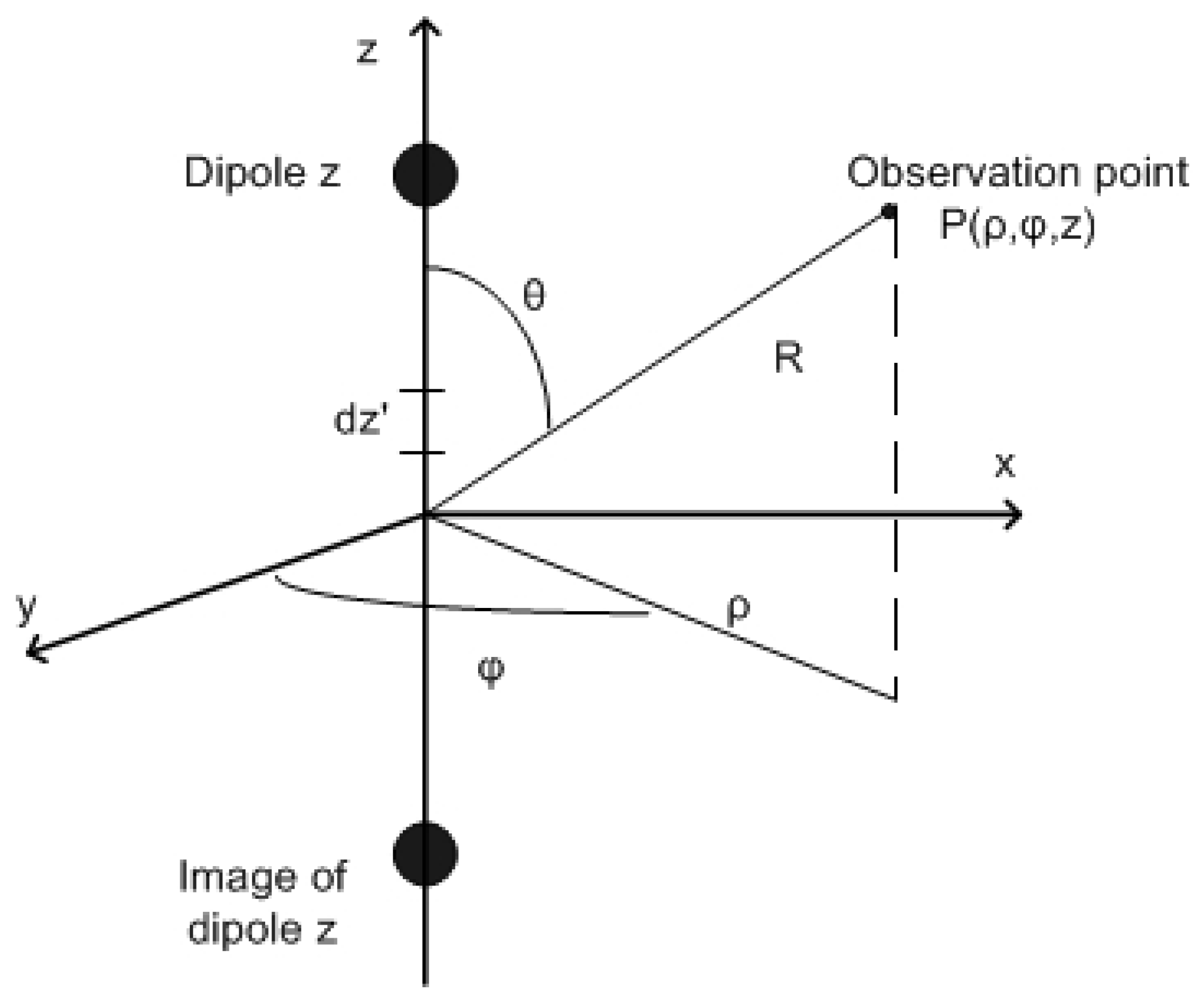
3. ESD Radiated Fields Approach Using the Dipole Model

The fields caused by ESD currents can couple to vulnerable internal circuits or directly enter equipment through openings such as apertures, seams, vents, and others. Therefore, at frequencies where issues are anticipated, the designer tries to reduce this coupling. Inefficient receivers must also be ineffective heaters, according to the law of reciprocity. Circuits that are voltage-sensitive and have high resistance tend to be excited by electric fields. Therefore, unwanted coupling can be reduced by keeping the receiving antenna’s impedance at low levels. There are usually trade-offs, but this might improve magnetic field collection. Boxleitner [5] provides a thorough explanation of the arrangement of circuit boards to reduce line–antenna issues.
Wilson and Ma [47] have modeled the E/M field of the ESD event utilizing the dipole in Figure 1, which is of length dl and is positioned above a perfect ground. A cylinder-shaped coordinate system (p, φ, z) is placed in the center of the dipole, and its mirror image at z = z′ is applied. Figure 1 shows the dipole as being above earth, but actual ESD incidents take place very near the victim conductor. Therefore, the dipole is permitted to touch the earth, or z′ = 0. R is the distance variable from the observation point to the source.
Figure 1. The dipole source model.

4. Electromagnetic Field Measurement Radiated by ESD

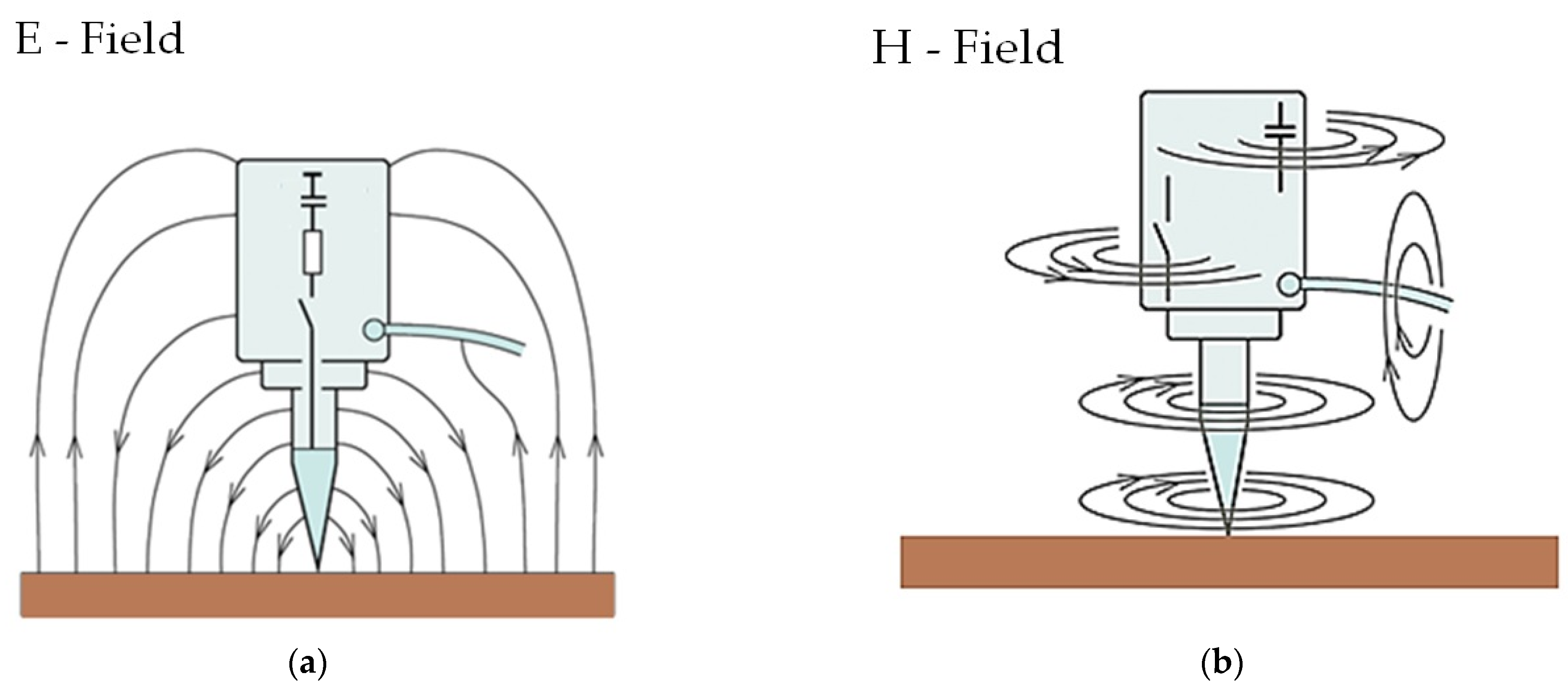
4.1. Electric and Magnetic Field Coupling of the ESD Generator

The IC’s susceptibility to ESD is rising. The shrinking structural width of ICs is one cause of this greater sensitivity. Microcontrollers and application-specific integrated circuits (ASICs) are presently getting close to 10 nm. Higher switch rates for the transistor cells are made possible by shrinking structural geometries, which also lower the supply voltage. This inevitably makes ICs more susceptible to influence.
Typically, the ESD generator looks like a gun with a metal point. This metal tip is used to test “contact discharge” by lightly touching metallic components of the test apparatus to start the test pulse. The interference is pertinent to the current pulse that was introduced. This ESD current waveform is described in IEC 61000-4-2 [15]. The interference effect during the test process should be defined by its curve shape parameters. In real life, curve form specifications are not always tracked by the ESD generator. There are interference events that are challenging to understand. For instance, some EUT may only encounter interference when facing the right side of the generator, with no interference from the left or other sides. Fields from the generator’s housing that act on the EUT can explain this.
Rapid transient magnetic and electric fields are radiated by ESD generators. During testing, the EUT may be affected by these fields that come from the ESD generator’s casing. The electrical circuit’s ICs will consequently respond with failures in accordance with their sensitivity. The maker and technology have an impact on an IC’s sensitivity. An IC’s ability to detect and generate mistakes from shorter disturbance pulses increases with speed. These fields are generated by the structural elements inside the ESD generators. The toggling of the high voltage switch produces electric fields (Figure 2a). The consequent recharge currents result in magnetic fields (Figure 2b).
Figure 2. Coupling of the ESD generator for (a) the electric field and (b) the magnetic field.

4.2. Measurement Setups and Instrumentation for the Measurement of the E/M Field Produced by ESD

Table 1 presents the most significant research works on the E/M field measurement by electrostatic discharges with other measured magnitudes derived by the same experimental setups. Takai et al. [48] make recommendations for measurement tools designed specifically for E/M fields generated by ESD near electronic equipment. The observed EMI intensity is a relative number because this measurement apparatus was created with the intention of identifying ESD and documenting the moment it occurred.
Table 1. Summary of measurement configurations for the E/M field radiated by electrostatic discharges.
Ref. Measured Magnitudes Discharge Type
Discharge Current Electric Field Magnetic Field Optical Radiation Induced Voltages  
[48]   X X   Χ Both air and contact discharges
[49]   X X     Contact discharges
[50][51][52] X   X X   Air discharges
[53] X X X     Both air and contact discharges
[54] X X X   X Contact discharges
[55] X X X     Contact discharges
[56] X X X   X Both air and contact discharges
[22] X X X   X Contact discharges
[37][38] X X X     Contact discharges
[39] X X X     Contact discharges
[15] X X X     Contact discharges

Bendjamin examined the magnetic field and optical radiation produced by electrostatic discharges [50][51][52]. The results presented showed that by reducing the conductivity of the material that the EUT is made from, one can reduce the peak current as well as the peak derivative of the magnetic field. 

Even though ESD current curves for different generators are similar, regarding the Imax, tr, I30, and I60 parameters, tests show different outcomes (pass or fail) for the same EUT depending on the generator that has been used. This occurs because there is no specification for the generated transient field that differs for each ESD generator. The test’s repeatability must be improved by such a specification. Working in this direction, Pommerenke [55] investigates the requirements for the current derivative, fields, and induced voltages produc

4.3. E and H Field Sensors for the Measurement of the Electromagnetic Field from ESD

4.3.1. Ground-Based Field Sensors with Active Integration

A ground-based field sensor type with active integration has been created [37][38][53] using a multistep analog integration for the H-field sensor and an impedance converter made of GaAs for the E-field sensor. They are roughly 4 cm by 3 cm by 1 cm in size and have a rectangular shape.
The E-field sensor has a dynamic range of 20 V/m to 20 kV/m. When measured in an open strip line, the sensor has a 1.5 dB frequency response from 2.5 MHz to 2 GHz. Using a frequency response setup, the sensor’s 194 uV(V/m) sensitivity can be calibrated.

4.3.2. Passive E- and H-Field Sensors

The E-field sensors are ball probes that can detect signals up to 2.5 GHz and were used to measure the electric field [50][51]. The ball probe shaft is constructed of a length of 50-ohm coax. The coax is terminated at its end with a 50-ohm resistor to present a conjugate termination to the 50 ohm line. Then, the center conductor is extended beyond the 50 ohm termination and attached to a metal ball. The ball serves as an E-field pick-up. However, the absence of a closed loop prevents current flow, allowing the ball probe to reject the H-field.

5. Comparison of Experimental Results from the International Literature

At this point, it is necessary to compare the experimental results for the measurement of the E/M field, as derived by various researchers. It must be emphasized that the study of the field produced by electrostatic discharges is a particularly difficult issue due to the rapid transient phenomenon of electrostatic discharge, which requires the use of specially constructed sensors. For this reason, there have been different results both in terms of the form of the magnetic or electric field produced and in terms of the values that are measured each time.
In [39], measurements of the E/M field were presented using passive sensors manufactured by Rohde & Schwartz, when the coaxial measuring adapter was on an insulating material. The same type of sensor has been used by Bendjamin [50][51], who tried to examine the characteristics of electrostatic discharge based on the current, optical radiation, and the generated E/M field. He measured the radiated electric and magnetic fields for air discharges in small gaps. A comparison between the experimental results of these two researchers proves that there are some differences in the measured E/M field. This has to do with differences in the experimental setups, the different types of generators and equipment that have been used to carry out the experiments, and the fact that the discharges studied by Bendjamin were air discharges and not contact discharges. It must be noted that due to the lack of specific measuring equipment for the E/M field, various researchers have been enabled in such measurements using different equipment and measuring setups.

6. Conclusions

The different magnetic or electric fields, produced by different generators or by the same generator depending on its orientation, result in the induced voltages at adjacent points also being different. This implies that a test that is conducted by one generator passes the test according to IEC standard 61000-4-2 [15], while the other fails. This fact demonstrates the necessity of studying the E/M field produced by the various electrostatic discharge generators so that in the next revision of the standard [15] there will be manufacturing instructions for these generators, which will determine the limits of the generated fields. The fact that there is an asymmetry in the distribution of the E/M field around the electrostatic discharge generator occurs because of (a) the asymmetrical high voltage relays inside the generators and (b) the position of the generator ground cable. During the experiments, the ground wire must be in the same position so that the measurements of the produced field are repeatable.
Annex D of the current IEC 61000-4-2 is on the radiated fields from human metal discharge and ESD generators. However, Annex D is informative and the described measurement techniques are not compulsory. In the upcoming revision of the standard [15], the E/M field parameter, produced by electrostatic discharge generators, could be included as mandatory. Specifically, the setup that will be used for the measurement of the E/M field should be defined. The sensors should be similar to those of D. Pommerenke [55]. At the same time, limits could be set for some parameters of the magnitudes of the field during its verification, such as the maximum field strength of the electric or magnetic field, Emax and Hmax, respectively, the rise time of the electric or magnetic field, and, possibly, values of the field’s change (derivative). Additionally, the measurement of the E/M field during the verification of the generators should be done around 360 degrees, which is of course quite difficult from the point of view of implementation for the laboratories around the world. In this way, the uncertainty during the verification of the generators will be reduced, while the tests on real samples will be more reliable since their repeatability will be ensured to a greater extent than now. The research outcome for the prediction of the E/M field in [40][41][42] should also be included in the standard’s next revision, since it will be a valuable tool for the laboratories involved in ESD testing.

References

  1. Wang, A. Practical ESD Protection Design, 1st ed.; Wiley: Hoboken, NJ, USA; IEEE Press: Piscataway, NJ, USA, 2021.
  2. Bafleur, M.; Caignet, F.; Nolhier, N. ESD Protection Methodologies: From Component to System, 1st ed.; ISTE Press–Elsevier: Amsterdam, The Netherlands, 2017.
  3. Richman, P. ESD Simulation-Configuring a Full-Performance Facility. In Proceeding of the IEEE International Symposium on Electromagnetic Compatibility, Arlington, VA, USA, 23–25 August 1983; pp. 1–5.
  4. Duvvury, C.; Gossner, H. System Level ESD Co-Design; Wiley-IEEE Press: London, UK, 2015.
  5. Yousaf, J.; Shin, J.; Kim, K.; Youn, J.; Lee, D.; Hwang, C.; Nah, W. System level esd coupling analysis using coupling transfer impedance function. IEEE Trans. Electromagn. Compat. 2018, 60, 310–321.
  6. Muchaidze, G.; Koo, J.; Cai, Q.; Li, T.; Han, L.; Martwick, A.; Wang, K.; Min, J.; Drewniak, J.L.; Pommerenke, D. Susceptibility scanning as a failure analysis tool for system-level electrostatic discharge (ESD) problems. IEEE Trans. Electromagn. Compat. 2008, 50, 268–276.
  7. Intra, P.; Tippayawong, N. Design and evaluation of a high concentration, high penetration unipolar corona ionizer for electrostatic discharge and aerosol charging. J. Electr. Eng. Technol. 2013, 8, 1175–1181.
  8. Wang, K.; Pommerenke, D.; Zhang, J.M.; Chundru, R. The PCB level ESD immunity study by using 3-dimension ESD scan system. In Proceedings of the International Symposium on Electromagnetic Compatibility, Silicon Valley, CA, USA, 9–13 August 2004; pp. 343–348.
  9. Honda, M. Fundamental aspects of esd phenomena and its measurement techniques. IEICE Trans. Commun. 1996, 79, 457–4616.
  10. Leo, G.C.R.D.; Primiani, V.M. ESD in electronic equipment: Coupling mechanisms and compliance testing. In Proceedings of the Industrial Electronics ISIE 2002, L’Aquila, Italy, 8–11 July 2002; pp. 1382–1385.
  11. Caniggia, S.; Maradei, F. Circuit and numerical modeling of electrostatic discharge generators. IEEE Trans. Ind. Appl. 2006, 42, 1350–1357.
  12. Pommerenke, D.; Fan, J.; Drewniak, J. Simulation challenges in system level electrostatic discharge modeling. In Proceedings of the IEEE/ACES International Conference on Wireless Information Technology and Systems (ICWITS) and Applied Computational Electromagnetics (ACES), Honolulu, HI, USA, 13–18 March 2016; pp. 1–2.
  13. Smith, D.C. Techniques for investigating the effects of ESD on electronic equipment. J. Phys. Conf. Ser. 2015, 646, 012036.
  14. Berghe, S.V.; Zutter, D.D. Study of signal entry through coaxial cable shields. J. Electrost. 1998, 44, 135–148.
  15. IEC 61000-4-2; Electromagnetic Compatibility (EMC)-Part 4-2: Testing and Measurement Techniques Electrostatic Discharge (ESD) Immunity Test. IEC: London, UK, 2008.
  16. Fotis, G.; Gonos, I.F.; Assimakopoulou, F.E.; Stathopulos, I.A. Applying genetic algorithms for the determination of the parameters of the electrostatic discharge current equation. Inst. Phys. (IOP) Proc. Meas. Sci. Technol. 2006, 17, 2819–2827.
  17. Fotis, G.; Gonos, I.F.; Stathopulos, I.A. Determination of the Discharge Current Equation Parameters of ESD using Genetic Algorithms. IEE Electron. Lett. 2006, 42, 797–799.
  18. Katsivelis, P.; Fotis, G.; Gonos, I.F.; Koussiouris, T.G.; Stathopoulos, I.A. Electrostatic Discharge Current Linear Approach and Circuit Design Method. Energies 2010, 3, 1728–1740.
  19. Fotis, G.; Vita, V. Circuit Modeling and Simulation of the ESD Generator for Various Tested Equipment According to the IEC 61000-4-2. WSEAS Trans. Circuits Syst. 2022, 21, 193–201.
  20. Yousaf, J.; Shin, J.; Lee, H.; Youn, J.; Lee, D.; Hwang, C.; Nah, W. Esd triggered current analysis for floating eut with/without shielding of esd generator. In Proceedings of the 16th International Symposium on Microwave and Optical Technology, Seoul, Republic of Korea, 26–28 June 2017; p. 1.
  21. Yousaf, J.; Shin, J.; Leqian, R.; Nah, W.; Youn, J.; Lee, D.; Hwang, C. Effect of ESD generator ground strap configuration on esd waveform. In Proceedings of the Asia-Pacific International Symposium on Electromagnetic Compatibility (APEMC), Seoul, Republic of Korea, 20–23 June 2017; pp. 121–123.
  22. Caniggia, S.; Maradei, F. Numerical prediction and measurement of ESD radiated fields by free-space field sensors. IEEE Trans. Electromagn. Compat. 2007, 49, 494–503.
  23. Zhang, J.; Beetner, D.G.; Moseley, R.; Herrin, S.; Pommerenke, D. Modeling electromagnetic field coupling from an ESD generator to an IC. In Proceedings of the Electromagnetic Compatibility (EMC) IEEE International Symposium, Long Beach, California, USA, 14–19 August 2011; pp. 553–558.
  24. Park, M.; Park, J.; Kim, J.; Seung, M.; Choi, J.; Lee, C.; Lee, S. Measurement and modeling of system level ESD noise voltages in real mobile products. In Proceedings of the 2016 Asia-Pacific International Symposium on Electromagnetic Compatibility (APEMC), Shenzhen, China, 17–21 May 2016; pp. 632–634.
  25. Lee, J.; Lim, J.; Jo, C.; Seol, B.; Nandy, A.; Li, T.; Pommerenke, D. A study of a measurement and simulation method on ESD noise causing soft errors by disturbing signals. In Proceedings of the 33rd EOS/ESD Symposium Proceedings, Anaheim, CA, USA, 11–16 September 2011; pp. 1–5.
  26. Antong, R.; Low, D.; Pommerenke, D.; Abdullah, M.Z. Prediction of electrostatic discharge (ESD) soft error on two-way radio using ESD simulation in CST and ESD immunity scanning technique. In Proceedings of the 36th International Electronics Manufacturing Technology Conference, Johor Bahru, Malaysia, 11–13 November 2014; pp. 1–10.
  27. Centola, F.; Pommerenke, D.; Kai, W.; Doren, T.V.; Caniggia, S. ESD excitation model for susceptibility study. In Proceedings of the IEEE Symposium on Electromagnetic Compatibility. Symposium Record (Cat. No. 03CH37446), Boston, MA, USA, 18–22 August 2003; pp. 58–63.
  28. Fujiwara, O.; Zhang, X.; Yamanaka, Y. FDTD simulation of electrostatic discharge current by ESD testing. IEICE Trans. Commun. 2003, 86, 2390–2396.
  29. Lee, J.S.; Pommerenke, D.; Lim, J.D.; Seol, B.S. ESD field coupling study in relation with PCB GND and metal chassis Pommerenke, D. In Proceedings of the 20th International Zurich Symposium on Electromagnetic Compatibility, Zurich, Switzerland, 12–16 January 2009; pp. 153–156.
  30. Kim, K.H.; Kim, Y. Systematic analysis methodology for mobile phone’s electrostatic discharge soft failures. IEEE Trans. Electromagn. Compat. 2011, 53, 611–618.
  31. Park, J.; Lee, J.; Seol, B.; Kim, J. Efficient calculation of inductive and capacitive coupling due to electrostatic discharge (ESD) using PEEC method. IEEE Trans. Electromagn. Compat. 2015, 57, 743–753.
  32. Nieden, F.; Scheier, S.; Frei, S. Circuit models for ESD-generator-cable field coupling configurations based on measurement data. In Proceedings of the Electromagnetic Compatibility (EMC EUROPE), Rome, Italy, 17–21 September 2012; pp. 1–6.
  33. Yoshida, T.; Masui, N. A study on system-level ESD stress simulation using circuit simulator. In Proceedings of the 2013 Asia-Pacific Symposium on Electromagnetic Compatibility (APEMC), Melbourne, VIC, Australia, 20–23 May 2013; pp. 1–4.
  34. Yoshida, T. A study on transmission line modeling method for system-level ESD stress simulation. In Proceedings of the 2015 Asia-Pacific Symposium on Electromagnetic Compatibility (APEMC), Taipei, Taiwan, 26–29 May 2015; pp. 577–580.
  35. Xiu, Y.; Thomson, N.; Mertens, R.; Rosenbaum, E. S-parameter based modeling of system-level ESD test bed. In Proceedings of the 37th Electrical Overstress/Electrostatic Discharge Symposium (EOS/ESD), Reno, NV, USA, 27 September–2 October 2015; pp. 1–10.
  36. Zhao, S.; Zhou, C.; Liang, Z.; Qian, Z.; Wang, Z. Modeling electromagnetic immunity of ldo under ESD electromagnetic field coupling. In Proceedings of the Asia-Pacific International Symposium on Electromagnetic Compatibility (APEMC), Shenzhen, China, 17–21 May 2016; pp. 355–358.
  37. Fotis, G.; Gonos, I.F.; Stathopulos, I.A. Measurement of the electric field radiated by electrostatic discharges. Inst. Phys. (IOP) Proc. Meas. Sci. Technol. 2006, 17, 1292–1298.
  38. Fotis, G.; Rapanakis, A.G.; Gonos, I.F.; Stathopulos, I.A. Measurement of the magnetic field radiating by electrostatic discharges during the verification of the ESD generators. J. Int. Meas. Confed. 2007, 40, 428–436.
  39. Fotis, G.; Christodoulou, C.A.; Pippis, C.D.; Ekonomou, L.; Zafeiropoulos, I.; Maris, T.I.; Karamousantas, D.C.; Chatzarakis, G.E.; Gonos, I.F.; Stathopulos, I.A. Measurement of the electromagnetic field radiating by commercial ESD generators with the Pellegrini target on insulating material. J. Int. Meas. Confed. 2009, 42, 1073–1081.
  40. Fotis, G.; Ekonomou, L.; Maris, T.I.; Liatsis, P. Development of an artificial neural network software tool for the assessment of the electromagnetic field radiating by electrostatic discharges. IEE Proc. Sci. Meas. Technol. 2007, 1, 261–269.
  41. Ekonomou, L.; Fotis, G.; Maris, T.I.; Liatsis, P. Estimation of the electromagnetic field radiating by electrostatic discharges using artificial neural networks. Simul. Model. Pract. Theory 2007, 15, 1089–1102.
  42. Fotis, G.; Vita, V.; Ekonomou, L. Machine Learning Techniques for the Prediction of the Magnetic and Electric Field of Electrostatic Discharges. Electronics 2022, 11, 1858.
  43. Miao, M.; Zhou, Y.; Salcedo, J.A.; Hajjar, J.-J.; Liou, J.J. A New Method to Estimate Failure Temperatures of Semiconductor Devices Under Electrostatic Discharge Stresses. IEEE Electron Device Lett. 2016, 37, 1477–1480.
  44. Byrne, W.W. The meaning of electrostatic discharge (ESD) in relation to the human body characteristics and electronic equipment. In Proceedings of the IEEE International Symposium on Electromagnetic Compatibility, Arlington, VA, USA, 23–25 August 1983; pp. 1–12.
  45. Gaskill, S.G.; Davuluri, P. Equivalent Circuit for I/O Electrical Fast Transient Testing. In Proceeding of the IEEE International Symposium on Electromagnetic Compatibility & Signal/Power Integrity (EMCSI), Spokane, WA, USA, 1–5 August 2022; pp. 141–145.
  46. Woods, M.H.; Gear, G. A new electrostatic discharge failure mode. IEEE Trans. Electron Devices 1979, 26, 16–21.
  47. Wilson, P.F.; Ma, M.T. Fields radiated by electrostatic discharges. IEEE Trans. Electromagn. Compat. 1991, 33, 10–18.
  48. Takai, T.; Kaneko, M.; Honda, M. One of the methods of observing ESD around electronic equipment. J. Electrost. 1998, 42, 305–320.
  49. Frei, S.; Pommerenke, D. A transient field measurement system to analyze the severity and occurrence rate of electrostatic discharge (ESD). J. Electrost. 1998, 44, 191–203.
  50. Bendjamin, J.; Gomes, C.; Cooray, V. Remote sensing of ESD through optical and magnetic radiation fields. IEEE Trans. Dielectr. Electr. Insul. 1999, 6, 896–899.
  51. Bendjamin, J.; Thottappillil, R.; Scuka, V. Time varying electromagnetic fields generated by electrostatic discharges. In Proceedings of the 1st IEEE International Symposium on Polymeric Electronics Packaging, PEP ‘97 (Cat. No.97TH8268), Norrkoping, Sweden, 30 October 1997; pp. 197–202.
  52. Bendjamin, J.; Thottappillil, R.; Scuka, V. Time varying magnetic fields generated by human metal (ESD) electrostatic discharges. J. Electrost. 1999, 46, 259–269.
  53. Pommerenke, D.; Aidam, M. ESD: Waveform calculation, field and current of human and simulator ESD. J. Electrost. 1996, 38, 33–51.
  54. Frei, S.; Pommerenke, D. Fields on the horizontal coupling plane excited by direct ESD and discharges to the vertical coupling plane. J. Electrost. 1998, 44, 177–190.
  55. Wang, K.; Pommerenke, D.; Chundru, R.; Van Doren, T.; Drewniak, J.L.; Shashindranath, A. Numerical modeling of electrostatic discharge generators. IEEE Trans. Electromagn. Compat. 2003, 45, 258–271.
  56. Chundru, R.; Pommerenke, D.; Wang, K.; Doren, T.V.; Centola, F.P.; Huang, J.S. Characterization of human Metal ESD reference discharge event and correlation of generator parameters to failure levels-part I: Reference event. IEEE Trans. Electromagn. Compat. 2004, 46, 498–504.
More
Information
Contributor MDPI registered users' name will be linked to their SciProfiles pages. To register with us, please refer to https://encyclopedia.pub/register :
View Times: 396
Revisions: 2 times (View History)
Update Date: 20 Jul 2023
1000/1000
Video Production Service