Your browser does not fully support modern features. Please upgrade for a smoother experience.
Submitted Successfully!
 +1 credit
Thank you for your contribution! You can also upload a video entry or images related to this topic.
For video creation, please contact our Academic Video Service.
| Version | Summary | Created by | Modification | Content Size | Created at | Operation |
|---|---|---|---|---|---|---|
| 1 | Jiří Jaromir Klemeš | -- | 2799 | 2023-07-18 14:02:11 | | | |
| 2 | Peter Tang | + 1 word(s) | 2800 | 2023-07-19 05:42:33 | | |
Video Upload Options
We provide professional Academic Video Service to translate complex research into visually appealing presentations. Would you like to try it?
Cite
If you have any further questions, please contact Encyclopedia Editorial Office.
Arsenyeva, O.; Tovazhnyanskyy, L.; Kapustenko, P.; Klemeš, J.J.; Varbanov, P.S. Plate Heat Exchangers and Their Types of Construction. Encyclopedia. Available online: https://encyclopedia.pub/entry/46929 (accessed on 21 July 2026).
Arsenyeva O, Tovazhnyanskyy L, Kapustenko P, Klemeš JJ, Varbanov PS. Plate Heat Exchangers and Their Types of Construction. Encyclopedia. Available at: https://encyclopedia.pub/entry/46929. Accessed July 21, 2026.
Arsenyeva, Olga, Leonid Tovazhnyanskyy, Petro Kapustenko, Jiří Jaromír Klemeš, Petar Sabev Varbanov. "Plate Heat Exchangers and Their Types of Construction" Encyclopedia, https://encyclopedia.pub/entry/46929 (accessed July 21, 2026).
Arsenyeva, O., Tovazhnyanskyy, L., Kapustenko, P., Klemeš, J.J., & Varbanov, P.S. (2023, July 18). Plate Heat Exchangers and Their Types of Construction. In Encyclopedia. https://encyclopedia.pub/entry/46929
Arsenyeva, Olga, et al. "Plate Heat Exchangers and Their Types of Construction." Encyclopedia. Web. 18 July, 2023.
Copy Citation
A plate heat exchanger (PHE) is a modern, effective type of heat transfer equipment capable of increasing heat recuperation and energy efficiency. For PHEs, enhanced methods of heat transfer intensification can be further applied using the analysis and knowledge already available in the literature.
plate heat exchanger
heat transfer
pressure drop
energy efficiency
heat recuperation
1. PHEs and Their Types of Construction
A plate heat exchanger (PHE) is a heat exchanger with a primary heat transfer surface consisting of a number of heat transfer plates fabricated by stamping or other kinds of forceful, non-intruding deformation from thin sheet material. The interesting areas of printed circuit heat exchangers, as described in [1], and microchannel heat exchangers [2] are beyond the scope of the current entry.
The main features of modern PHE construction, making them energy-efficient and reliable heat exchangers under different process conditions, are [3]:
- (i)
-
A large number of contact points between adjacent plates in the plate pack that form a strong structure capable of withstanding large differential pressures between streams in channels [4]. This allows for plates of small thicknesses down to about 0.3 mm, decreasing the consumption of costly metals and the PHE weight;
- (ii)
-
The PHE channels with contact points for the corrugations inside have a geometrical form inducing a change in flow direction and high levels of turbulence, swirl and vortex structures. This happens even at relatively low Reynolds numbers, as shown by various researchers (see, e.g., [5]). It creates a peculiar mechanism of heat transfer enhancement with a rather smooth transition from a laminar to a turbulent flow regime;
- (iii)
-
Heat transfer coefficients in PHEs are much higher than in traditional shell-and-tube heat exchangers, and a significantly smaller heat transfer area is required, which makes them much more compact, with smaller area needs for maintenance;
- (iv)
-
The area of the heat transfer surface in PHEs is made of thin metal plates and requires much less material than in shell-and-tube heat exchangers. This makes it possible to achieve lower costs, even when more expensive materials are used [6];
- (v)
-
Often, the temperature approach of the streams in PHEs can be reduced to 1 °C, which makes them useful for maximal heat recuperation in heat exchanger networks (HENs) [7];
- (vi)
-
By adjusting the geometries of plate corrugations, the performance of PHEs can be optimised for specific process conditions [8]. This can be achieved by assembling one of the PHEs from plates with different corrugations that enable close (within an error of one plate) satisfaction of the required duty;
- (vii)
-
The low weight of PHEs means lower costs for transport and fewer requirements for the foundation;
- (viii)
-
The low hold-up volume of PHEs with narrow channels makes them suitable for treating dangerous or expensive fluids. Low PHE weight ensures easier control of process parameters;
- (ix)
-
The possibility of handling multiple streams in one PHE enables the simplification of the process unit and increases its compactness;
- (x)
-
Easy disassembly of plate-and-frame PHEs enables mechanical cleaning, rearranging and changing of a number of plates to flexibly satisfy the required changes in process requirements;
- (xi)
-
The heat losses to surroundings in PHEs are considerably reduced, as the plates are in contact with ambient air only at their side edges.
The main disadvantages of PHEs at all stages of their development during the period of about a century since their first applications in the dairy industry are the limited range of working conditions in terms of temperature and pressure and their unreliable operation outside this range. The main elements limiting the range of plate-and-frame PHE applications are the rubber gaskets and the places of their fixation on the plates. These limitations stimulated the development of new types of PHE construction that did not use rubber gaskets to seal the PHE channels. Welded PHE (WPHE) types have been developed where the plates are welded to seal the channels, and brazed PHEs (BPHEs) have the plates brazed together at contact points using additional filler metal (fusion-bonded PHEs can also be considered as this PHE type). Nowadays, most commercially produced PHEs have corrugations inclined to the plate axis, forming channels of crisscrossing flow types between them. The main principles of heat transfer intensification in these channels remain the same in all PHE construction types. However, some features of the thermal and hydraulic design are strongly influenced by the type of PHE construction. The three main types of PHEs are described below to analyse recent developments in more detail.
2. Plate-and-Frame PHEs
The history of PHEs started with the plate-and-frame type. Now, it is a traditional type of construction, the main principles of which have not changed in our century (see Figure 1). However, research to improve its elements and mechanical properties is still ongoing. Examples include studies of gasket groove mechanical performance [9] and PHE structural strength [4]. Various modifications of the ports and connections have been introduced, making it possible to handle large volumes of vapour for condensation as well as evaporation duties [10]. Extensive work has also been performed on the mechanical properties of plates and the technology for their stamping. The results of such research are mostly under the possession of leading PHE manufacturing companies and are out of this entry’s scope. An important note must be added about stamping technology, where the springing of metal after the stamping has to be exactly accounted for to avoid uneven depth in the corrugations in the plate field. If it is not, the thermal and hydraulic performance of the PHE will be significantly jeopardised, as, under the differential pressure between streams, the channels will not be similar and will deform against the designed parameters.
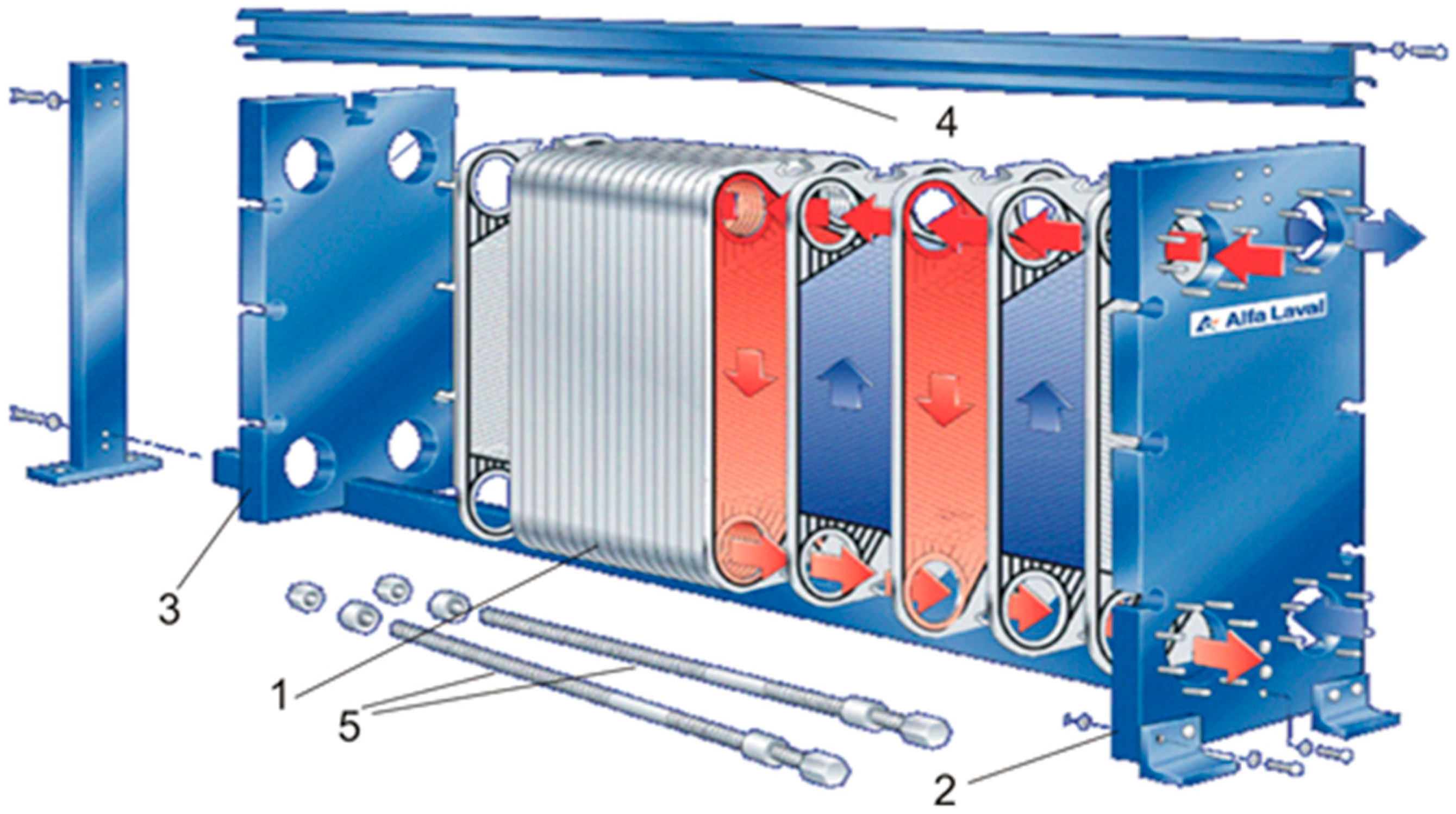
Figure 1. Plate-and-frame PHE (construction scheme): 1—stack of plates with gaskets; 2—fixed-frame plate; 3—moving plate of frame; 4—carrying bar; 5—tightening bolts (courtesy of OAO Alfa Laval Potok, Korolev, Moscow region, Russian Federation).
High temperatures, dynamic loads and contact with acids, hydrocarbons, organic solvents, ozone, steam and oxygen lead to the ageing and deformation of gaskets. A better understanding of gasket ageing can help to expand the applications of gasketed PHEs (GPHEs). The commonly used acrylonitrile-butadiene rubber (NBR) and ethylene-propylene-diene monomer (EPDM) gaskets were studied by de Souza et al. [11]. The results showed that the existence of a groove could reduce the side thermo-oxidation and that EPDM gaskets had more reliable behaviour during the experiment, where the compression in a groove was maintained for up to 360 h at 100 and 120 °C. In another paper by Zanzi et al. [12], nitrile-butadiene rubber (NBR) gaskets were investigated. The study was performed on the different geometries of gaskets, investigating the ageing under different thermo-oxidative cycles. The experiments were carried out at temperatures from 80 to 170 °C for up to 180 days. The lifetime prediction of service conditions was obtained, showing that temperature is the most influential parameter for NBR gasket ageing. Correct prediction of elastomer gaskets’ behaviour would help to create the proper maintenance schedule for PHEs, reducing losses and costs.
A study of the metal bushing ring in GPHEs was carried out by Tian et al. [13], as the metal bushing ring is used for the inlet and outlet connections of the PHE and should prevent fluid leakage during operation. The authors investigated the possibility of implementing the drawing–flaring process, which consists of the deep-drawing and multi-flaring processes forming the metal bushing rings. It can avoid the negative effects of welding seams, which can cause leakages. This paper emphasised the differences between the technologies of different manufacturers. Leading producers have not used welding seams for this element in PHEs for more than 40 years.
The details of the mechanical design of PHEs are not within the main scope of this research. Here, the researchers present only the operational parameters of plate-and-frame GPHEs, which must be accounted for in their selection. The plates can be stamped using different metals suitable for cold stamping (commonly, the stainless steels AISI 304 and AISI 316), with thicknesses down to about 0.4 mm. More sophisticated alloys, such as alloy 254 SMO, alloy C-276, titanium, palladium-stabilized titanium, Incoloy and Hastelloy, are used for highly corrosion-aggressive media. The most limiting element of GPHEs is the elastomer gasket. The commonly used gaskets are made from nitrile rubber (NBR) and ethylene-propylene-diene rubber (EPDM) with numerous modifications. The usual temperature range of their operation is from −45 °C to 150 °C. New gasket materials [14] and forms [11] are being developed, and now this range can be widened to −60 °C to 200 °C with more specialised gaskets. In the case of sophisticated gaskets, their cost can exceed the costs of all other elements of the PHE. The working pressure range for plate-and-frame PHEs is from vacuum conditions up to 25 bar. At high pressure, thick frame plates are required, and they can constitute most of the PHE’s weight while being made from cheaper steel than the heat transfer area. Frames are produced for different pressure ranges, usually up to 10 bar, 16 bar and 25 bar, to avoid this excessive weight.
3. Brazed PHEs
The rubber gaskets and massive frame pressure plates are eliminated in brazed PHEs (BPHEs), which were originally developed in 1977. The adjacent plates in BPHEs are brazed at multiple contact points where their corrugations cross, as shown in Figure 2. This type of construction is capable of withstanding pressure in channels and does not need clamping by pressing the frame plates. The brazing on the plate edges seals the channels, avoiding the need for gaskets and places for their mounting. The plates are produced by stamping from a sheet of stainless steel, with thicknesses as small as 0.3 mm. Sheets of brazing metal about 0.1 mm thick are inserted between the plates to assemble the BPHE, which is finally placed in a vacuum oven to undergo thermal treatment with a specific program. Copper is most common as a brazing material, but when it is not resistant to aggressive media, such as ammonia, nickel can be used. Ni brazing filler metal has a high melting point, and additionally, Si, B and P can be added into Ni or Ni-Cr alloys to lower their melting point and improve the fluidity in their liquid state. Research on developing brazing technology with nickel is ongoing. For example, the authors of [15] presented the development of a new technology allowing the use of electrolytic Ni-P plating film as brazing filler metal with better wettability conditions, enabling reduced corrosion of the brazed area in an aqueous environment. A further advance was the creation of fusion-bonded PHEs [16], which have the same construction as BPHEs but with fusion bonding instead of brazing. This allows for completely stainless steel PHEs.
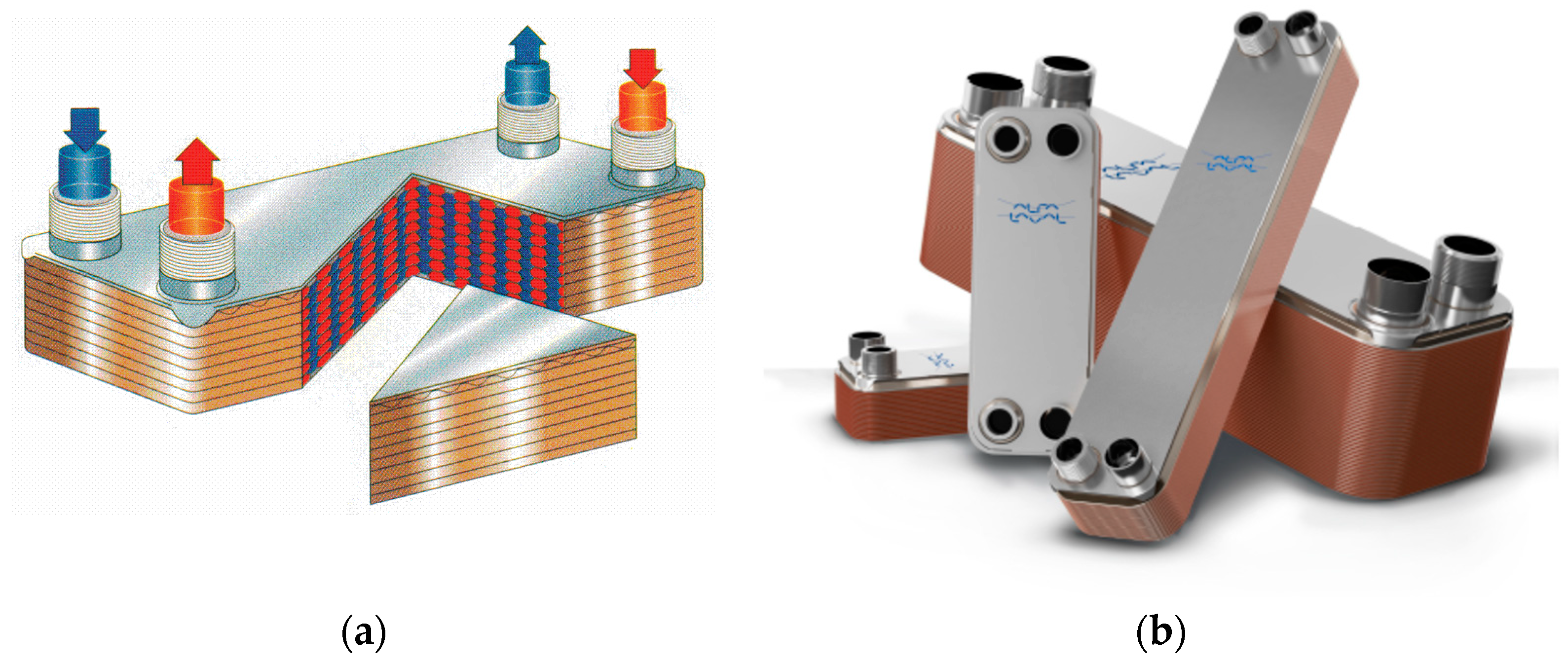
Figure 2. Brazed PHE: (a) drawing of streams’ movement; (b) example of fabricated BPHE (courtesy of OAO Alfa Laval Potok).
BPHEs are more compact and lower in weight than plate-and-frame PHEs. They are also cheaper in many cases. The standard operating conditions for copper-brazed BPHEs are temperatures from −196 °C to 225 °C and pressure from vacuum conditions to 30 bar. For some types, the pressure can be up to 90 bar or, with special frames, up to 130 bar. Fusion-bonded PHEs (e.g., AlfaNova [16]) can operate at temperatures up to 550 °C. The special construction of gas-to-liquid brazed PHEs with an asymmetric “dimple” plate design can withstand gas temperatures up to 750 °C, with the possibility of raising the limit to 1400 °C in some applications [16].
BPHEs are widely used in refrigeration, district heating, air conditioning, domestic boilers and other areas requiring low to medium heat capacities, almost entirely replacing conventional tubular heat exchangers. BPHEs can be successfully used for relatively clean fluids and where chemical cleaning is possible. The problems of fatigue can arise in unsteady conditions and in relation to vibrations caused, for example, by reciprocating compressors or steam hammering. In such conditions, the use of BPHEs requires extreme caution.
The main principles of the heat transfer intensification and design for BPHEs are the same as for plate-and-frame PHEs. However, the difference is the additional material at positions of plate contact points, which can change local hydrodynamics. Additionally, the absence of gaskets provides better flow conditions at the channel inlet and outlet, avoiding a decrease in the cross-section area in places where the gaskets seal the adjacent channel.
4. Welded PHEs
4.1. Welded Plate-and-Frame PHEs
The first attempt to avoid gaskets in PHEs was by welding plates in plate-and-frame PHEs. This type of PHE is very rare now, with more advanced special constructions emerging. Modifications such as semi-welded PHEs still hold their positions in a number of applications, especially in refrigeration. They consist of plate pairs welded together in twin-plate cassettes. One set of channels has only small, round gaskets; another has larger gaskets on the periphery, as in standard plate-and-frame PHEs but thicker. Such PHEs can handle aggressive fluids in one channel and, with a strong frame, withstand working pressure up to 63 bar. The significant advantage of semi-welded PHEs compared to welded ones is their much better operation with vibrations, as gaskets bring a dampening effect.
4.2. Welded Plate-and-Block PHEs
The most widely known and used welded PHE with plate-and-block construction is CompablocTM, schematically shown in Figure 3. It consists of a welded core, representing a heat transfer surface, encapsulated in a dismountable shell. From the view of thermal and hydraulic performance, it consists of a set of plate blocks. Each block has a cross-flow of streams. However, overall, counter-current flow exists across the whole of the PHE. From the viewpoint of thermal design, cross-flow in separate blocks causes a significant decrease in the average temperature difference in the PHE, which can be compensated by the overall counter-current flow. This depends on the required temperature program and the ratio of the two streams’ heat capacities. From a hydraulic viewpoint, the construction offers good distribution across the channel width and minimal local hydraulic resistance in the channel inlet and outlet. The welded construction with a special gasket at the assembled shell allows for an extension of the working parameters, ranging from temperatures of −46 °C to 370 °C at pressures from vacuum to 42 bar. The absence of gaskets not only allows for the widening of the range of working parameters but creates fatigue problems in unsteady conditions and in relation to vibrations caused, for example, by reciprocating compressors or steam hammering, which must be considered in all WPHE applications.
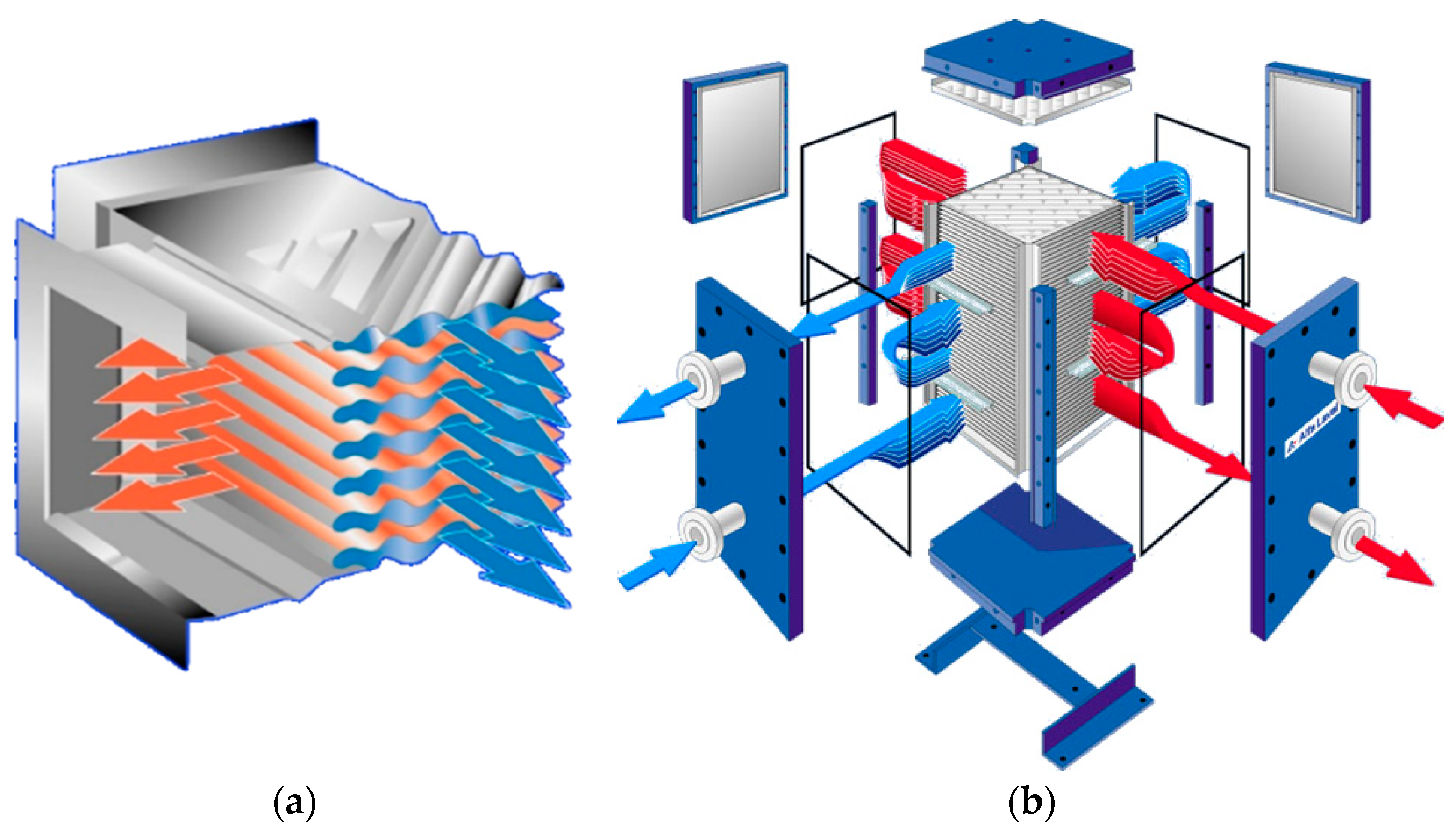
Figure 3. CompablocTM welded PHE: (a) plate pack schematic; (b) arrangement of cross-counter-current channels for stream flow (courtesy of OAO Alfa Laval Potok).
Presently, the main PHE manufacturers produce welded PHEs with similar constructions, e.g., FunkeBlock FPB, GEABloc®, APV Hybrid-Welded Heat Exchanger, etc. [3]. The operating range of these WPHEs is close to that of Compabloc but, excluding gaskets in the shell assembly, APV Hybrid is declared to work at temperatures from −200 °C to 900 °C and pressure up to 60 bar. The dismountable shell allows access to a heat transfer surface for cleaning with a pressure water jet or repair but limits the operation range. A similar block arrangement for a WPHE employed a high-pressure shell consisting of an ammonia synthesis column [17] and could operate at a pressure of 320 bar and a temperature of 520 °C.
4.3. Welded Plate-and-Shell PHEs
Work in the shell allows the Packinox welded PHE to operate in severe conditions related to catalytic reforming and other processes in chemical and petrochemical industries. Without a separate shell reinforced by frame plates and frame, Packinox can operate at temperatures up to 400 °C and pressures up to 70 bar [16]. Long corrugated plates are used in the construction with a strict counter-current flow of streams. This allows for significant improvements in heat recuperation.
Another principle for the channel arrangement is used in plate-and-shell WPHEs [18], shown in Figure 4. The pack of round plates is encased in a round shell, allowing for an arrangement with a parallel flow of streams: a counter-current in one-pass or mixed in multi-pass PHEs. Originally developed in 1990 at Vahterus Oy, with different modifications, it can work at pressures up to 150 bar and temperatures from −270 °C to 750 °C [19]. Now, WPHEs are manufactured with this principle by a number of other producers. As with all welded PHEs, they can have fatigue problems, which are investigated in, for example, [20].

Figure 4. Schematic drawing of plate-and-shell PHE (after Freire and de Andrade [18]).
Another modification of welded PHEs is the pillow-plate heat exchanger (PPHE), which consists of double-plate panels welded at multiple points and on the periphery. The panels are formed by pumping fluid at high pressure in a channel between the plates to achieve plastic deformation of the metal sheets between the welded points and to create an inside channel for the fluid flow of one stream. Being assembled in a pack, the panels form channels between them for another stream flow. The forms of the channels and their cross-sections are different, which allows the use of PPHEs for streams with very different flow rates and heat capacities, including in gas–liquid heat exchange and condensation and evaporation. The panels can be formed without expensive stamping tools. PPHEs are not considered here in more detail. A comprehensive survey of PPHE developments and research is available in [21].
References
- Ma, Y.; Xie, G.; Hooman, K. Review of printed circuit heat exchangers and its applications in solar thermal energy. Renew. Sustain. Energy Rev. 2021, 155, 111933.
- Lalagi, G.; Nagaraj, P.B.; Veerabhadrappa Bidari, M.; Hegde, R.N. Influence of design of microchannel heat exchangers and use of nanofluids to improve the heat Transfer and Pressure drop characteristics: A review. Int. J. Ambient. Energy 2022, 43, 6849–6877.
- Hesselgreaves, J.E.; Law, R.; Reay, D. Compact Heat Exchangers: Selection, Design and Operation; Butterworth-Heinemann: Oxford, UK, 2016.
- Martins, G.S.M.; Santiago, R.S.; Beckedorff, L.E.; Possamai, T.S.; Oba, R.; Oliveira, J.L.G.; de Oliveira, A.A.M.; Paiva, K.V. Structural analysis of gasketed plate heat exchangers. Int. J. Press. Vessel. Pip. 2022, 197, 104634.
- Dović, D.; Horvat, I.; Filipović, P. Impact of velocities and geometry on flow components and heat transfer in plate heat exchangers. Appl. Therm. Eng. 2021, 197, 117371.
- Hajabdollahi, H.; Naderi, M.; Adimi, S. A comparative study on the shell and tube and gasket-plate heat exchangers: The economic viewpoint. Appl. Therm. Eng. 2016, 92, 271–282.
- Wang, B.; Arsenyeva, O.; Zeng, M.; Klemeš, J.J.; Varbanov, P.S. An advanced Grid Diagram for heat exchanger network retrofit with detailed plate heat exchanger design. Energy 2022, 248, 123485.
- Arsenyeva, O.; Kapustenko, P.; Tovazhnyanskyy, L.; Khavin, G. The influence of plate corrugations geometry on plate heat exchanger performance in specified process conditions. Energy 2013, 57, 201–207.
- Kabil, B. Parameter Study of the Diagonal on a Gasketed Plate Heat Exchanger. Master’s Dissertation, Division of Solid Mechanics, Lund University, Lund, Sweden, 2022.
- AlfaLaval. Types of Gasketed Plate Heat Exchangers. 2022. Available online: https://www.alfalaval.com/microsites/gphe/types/ (accessed on 24 June 2023).
- de Souza, E.L.; de Souza Zanzi, M.; de Paiva, K.V.; Goes Oliveira, J.L.; Monteiro, A.S.; de Oliveira Barra, G.M.; Dutra, G.B. Evaluation of the aging of elastomeric acrylonitrile-butadiene rubber and ethylene-propylene-diene monomer gaskets used to seal plates heat exchanger. Polym. Eng. Sci. 2021, 61, 3001–3016.
- Zanzi, M.S.; de Souza, E.L.; Dutra, G.B.; Paiva, K.V.; Oliveira, J.L.G.; Cunha, T.V.; Monteiro, A.S. Service lifetime prediction of nitrile butadiene rubber gaskets used in plate heat exchangers. J. Appl. Polym. Sci. 2022, 139, 52523.
- Tian, C.; Zhang, D.-W.; Zhang, Q.; Zheng, Z.B.; Zhao, S.D. A drawing-flaring process of metal bushing ring without welding seam for plate heat exchanger. Int. J. Adv. Manuf. Technol. 2022, 121, 2539–2552.
- Trelleborg Sealing Solutions Plate Heat Exchanger Gaskets. 2022. Available online: https://www.trelleborg.com/en/seals/products-and-solutions/engineered-molded-parts/plate-heat-exchanger-gaskets (accessed on 24 June 2023).
- Hashimoto, A.; Liu, S.B.; Shohji, I.; Kobayashi, T.; Hirohashi, J.; Wake, T.; Arai, S.; Kamakoshi, Y. Brazing of Stainless Steel Using Electrolytic Ni-P Plating Film and Investigation of Corrosion Behavior. Mater. Sci. Forum 2021, 1016, 522–527.
- AlfaLaval. Plate Heat Exchangers. 2022. Available online: https://www.alfalaval.com/products/heat-transfer/plate-heat-exchangers/plate-heat-exchangers/ (accessed on 24 June 2023).
- Tovazhnyanskyy, L.; Klemeš, J.J.; Kapustenko, P.; Arsenyeva, O.; Perevertaylenko, O.; Arsenyev, P. Optimal Design of Welded Plate Heat Exchanger for Ammonia Synthesis Column: An Experimental Study with Mathematical Optimisation. Energies 2020, 13, 2847.
- Freire, L.O.; de Andrade, D.A. On applicability of plate and shell heat exchangers for steam generation in naval PWR. Nucl. Eng. Des. 2014, 280, 619–627.
- Vahterus. PSHE Construction. 2022. Available online: https://vahterus.com/technology/pshe-construction/ (accessed on 24 June 2023).
- Martins, G.S.M.; da Silva, R.P.P.D.; Beckedorff, L.; Monteiro, A.S.; de Paiva, K.V.; Oliveira, J.L.G. Fatigue performance evaluation of plate and shell heat exchangers. Int. J. Press. Vessel. Pip. 2020, 188, 104237.
- Joybari, M.M.; Selvnes, H.; Sevault, A.; Hafner, A. Potentials and challenges for pillow-plate heat exchangers: State-of-the-art review. Appl. Therm. Eng. 2022, 214, 118739.
More
Information
Subjects:
Engineering, Industrial; Engineering, Chemical
Contributors
MDPI registered users' name will be linked to their SciProfiles pages. To register with us, please refer to https://encyclopedia.pub/register
:
View Times:
1.8K
Revisions:
2 times
(View History)
Update Date:
19 Jul 2023
Table of Contents


Notice
You are not a member of the advisory board for this topic. If you want to update advisory board member profile, please contact office@encyclopedia.pub.
OK
Confirm
Only members of the Encyclopedia advisory board for this topic are allowed to note entries. Would you like to become an advisory board member of the Encyclopedia?
Yes
No
${ textCharacter }/${ maxCharacter }
Submit
Cancel
Back
Comments
${ item }
|
${ item.createdUser.fullName }
${ item.createdAt }
${ item.vote }
${ item.reply }
Delete
${ reply.createdUser.fullName }
${ reply.createdAt }
${ reply.vote }
Delete
There is no reply to this comment~
${ item.replyTextCharacter }/${ item.replyMaxCharacter }
Submit
Cancel
More
No more~
There is no comment~
${ textCharacter }/${ maxCharacter }
Submit
Cancel
${ selectedItem.replyTextCharacter }/${ selectedItem.replyMaxCharacter }
Submit
Cancel
Confirm
Are you sure to Delete?
Yes
No