Your browser does not fully support modern features. Please upgrade for a smoother experience.
Submitted Successfully!
 +1 credit
Thank you for your contribution! You can also upload a video entry or images related to this topic.
For video creation, please contact our Academic Video Service.
| Version | Summary | Created by | Modification | Content Size | Created at | Operation |
|---|---|---|---|---|---|---|
| 1 | Nikita Martyushev | -- | 9434 | 2023-06-26 10:26:42 | | | |
| 2 | Lindsay Dong | Meta information modification | 9434 | 2023-06-26 10:44:18 | | |
Video Upload Options
We provide professional Academic Video Service to translate complex research into visually appealing presentations. Would you like to try it?
Cite
If you have any further questions, please contact Encyclopedia Editorial Office.
Malozyomov, B.V.; Martyushev, N.V.; Kukartsev, V.V.; Tynchenko, V.S.; Bukhtoyarov, V.V.; Wu, X.; Tyncheko, Y.A.; Kukartsev, V.A. Methods for Enhanced Oil Recovery from Reservoirs. Encyclopedia. Available online: https://encyclopedia.pub/entry/46030 (accessed on 29 July 2026).
Malozyomov BV, Martyushev NV, Kukartsev VV, Tynchenko VS, Bukhtoyarov VV, Wu X, et al. Methods for Enhanced Oil Recovery from Reservoirs. Encyclopedia. Available at: https://encyclopedia.pub/entry/46030. Accessed July 29, 2026.
Malozyomov, Boris V., Nikita V. Martyushev, Vladislav V. Kukartsev, Vadim S. Tynchenko, Vladimir V. Bukhtoyarov, Xiaogang Wu, Yadviga A. Tyncheko, Viktor A. Kukartsev. "Methods for Enhanced Oil Recovery from Reservoirs" Encyclopedia, https://encyclopedia.pub/entry/46030 (accessed July 29, 2026).
Malozyomov, B.V., Martyushev, N.V., Kukartsev, V.V., Tynchenko, V.S., Bukhtoyarov, V.V., Wu, X., Tyncheko, Y.A., & Kukartsev, V.A. (2023, June 26). Methods for Enhanced Oil Recovery from Reservoirs. In Encyclopedia. https://encyclopedia.pub/entry/46030
Malozyomov, Boris V., et al. "Methods for Enhanced Oil Recovery from Reservoirs." Encyclopedia. Web. 26 June, 2023.
Copy Citation
Development systems, placement and choice of operating mode of wells essentially depend on the geological structure of the reservoir, its volume and properties of oils. An important role in this is the construction of a geological model of the production facility. The used hydrodynamic models of development are based on physical laws, about which oil producers sometimes don’t even suspect, and the authors of the models are not always able to convey it to the real producers.
EOR
oil reservoir
oil stimulation method
enhanced oil recovery method
1. Introduction
Since the 60s of the last centuries, issues related to the use of physico-chemical methods of enhanced oil recovery (PH EOR) in the development of oil fields have been of interest to oil specialists [1]. The structure of the reserves of developed deposits is changing; new fields with a more complex geological structure are being discovered, and new, more efficient technologies for developing oil fields are being introduced, but interest in reservoir stimulation technologies based on the use of various chemical compositions remains. This is due to the need to search for technical solutions “for tomorrow”, when drilling wells and regulating their operating modes, the introduction of new design approaches and optimization of the field development system as a whole will not be able to provide the required level of production and depletion of oil reserves [2]. Despite the large accumulated experimental and practical experience in the application of enhanced oil recovery methods, at present, there is a large gap between the needs of oilfield workers and the market supply of services for the implementation of these methods. The problem is also complicated by a significant reduction in the reagent base for PH EOR and, most importantly, the lack of a well-developed methodology for the use of certain compositions. When addressing these issues within the framework of the tender system for the provision of services, oil-producing enterprises are often guided by the accumulated practical experience in this area without the development and adaptation of new technologies.
Now, when almost all the world’s largest fields are at the advanced stages of development, a comprehensive study of the accumulated field experience in the implementation of PH-CH EOR and a reasonable classification of such methods are required to develop strategic approaches to their application and identify the most effective solutions for influencing certain groups of oil reservoirs [3].
This classification is largely based on the group division of generally accepted technical approaches using the terminology that has been developed in the industry, which, in fact, objectively reflects the chemical nature of the reagents used and the products of their interaction [4]. The authors do not claim the exclusivity and universality of the designated classification and the method of separation of technologies, but in the chosen format, there are specialists who consider a rational option for a single designation of various types of PH-CH EOR, showing their opinion on the directions and prospects for their use and further development [5]. When considering information sources, in most cases, the terminology and designations adopted by the authors of the original works were used.
In many old fields, the pressure filtration capabilities have almost exhausted their resource of possibilities. Further work on these deposits becomes economically unfeasible. Until now, this has been solved by increasing the price of oil and burning working capital from consumers of oil products. This, in turn, led to a crisis. The problem of extracting the maximum amount of geological reserves available in the reservoirs from oil-bearing reservoirs at acceptable costs, providing at least some profitability, is becoming urgent. The value of recoverable reserves varies widely (from 7–12% to 30–40%) and is determined not only by the geological conditions of the deposit but also by the technological method of field development, which provides certain values of oil recovery factors available for this method. These values of the development of geological reserves are the limits of traditional methods of development. Until recently, it was believed that the extraction of residual oil was impossible at all due to its immobility in the reservoir and the lack of technologies for extraction, which was true. Therefore, in world practice, huge reserves (from 50 to 90%) of hydrocarbon raw materials remain inaccessible for development and have not been fully developed [6]. The implementation of projects for deeper development of geological reserves requires novelty, and high technological and economic efficiency, which consists of a fundamental change not only in the traditional approach to the development of oil-saturated reservoirs but also in the laws of filtration. The laws of hydraulics are far from the natural laws of oil filtration in the reservoir. This has been established by research experience [7]. The traditional method of development is based on the laws of macro-hydrodynamics, where the decisive role is played by the viscosity of the fluids and the geometry of the pore channels of the reservoir rock. Traditional technologies have exhausted their resources and are not able to solve the problem of extracting hard-to-recover reserves, even theoretically. The creation of new technologies is based on new, deep fundamental knowledge, which radically changes the idea of an oil reservoir. The collector is a complex energy system, where not only physical forces play a decisive role but also the forces of intermolecular and interatomic interactions, as well as the energies of dynamic processes of fluid movement. Additionally, these are already elements of nano-technologies that provide a qualitative leap in the level of knowledge and the efficiency of their use. New science-intensive technologies for the development of oil and gas fields are based on the complete theory of filtration. Such criteria are met by technologies of electrophysical impact on oil reservoirs, allowing not only increasing the productivity of wells and extracting residual oil from depleted structures to produce the synthesis of the necessary chemical compounds. Contributing to the complete extraction of hydrocarbons and associated rare earth elements, the authors show that their cost can exceed the cost of oil by dozens of times. In this case, it shows where the solution to oil recovery problems is at a new level of knowledge. The technology of electrophysical impact can be considered as a natural and necessary improvement in the technology of developing oil and gas fields as a technique for using the general sensitivity of the rocks of an oil reservoir to electrical energy. They are modulated and configured to use certain given physical, chemical and dynamic characteristics of the oil-bearing reservoir and the fluids in it to regulate and control the processes occurring in the oil-bearing formation to intensify the inflow and increase oil recovery. Along with the impact of electrical energy on the oil reservoir, it has a wide range of manifestations, both positive and negative. Without knowing them, it is impossible to obtain the desired result. With the availability of appropriate techniques and correctly established modes of action, it is possible to obtain the desired technological effects for intensifying production, controlling filtration flows in the reservoir, and increasing oil recovery. In this way, the oil recovery factor can be multiplied. For hard-to-recover oils, the value of which is low, several times, it allows extending the terms of a profitable development of oil fields, reducing the cost of oil production. These include relatively small additional capital investments, in comparison with other methods of increasing oil recovery, by which it is simply impossible to achieve such values. The implementation of technological solutions requires the appropriate qualifications of specialists and maintenance personnel and additional capital investments for the development and maintenance of equipment and wells. Today, this is the main method that allows you to extract residual oil, acceptable in technical, technological and economic terms [8], providing reducing the cost of oil production and obtaining additional oil production at the expense of the non-recoverable part of geological reserves. This increases the resource base of oil-producing companies at least two times. Increasing the terms of profitable field development, increasing the number of jobs in the “old” oil-producing areas with the developed infrastructure, and protecting the environment in the development area. Considering the fact that the actual reserves of hydrocarbons on Earth are limited and exhausted as they are consumed, the possibility of obtaining additional residual oil from depleted structures can postpone the time of the energy oil collapse. The possibility of a deeper development of geological reserves is a vital necessity for world civilization.
The possibility of a deeper development of geological reserves is a vital necessity for world civilization.
Speaking about the importance of enhanced oil recovery and the current state of hydrocarbon development in different countries and large oil and gas fields, the use of additional EOR methods should be highlighted. Tertiary enhanced oil recovery (EOR) methods are enhanced oil recovery methods using complex technologies that change the original properties of reservoir fluids. They are used at the final stage of development but, in fact, can be applied at any time during the life of the field.
There are three most commonly used types of tertiary EOR: chemical, thermal and gas. The optimal application of each type depends on many factors: reservoir temperature, pressure, depth, permeability, residual oil and water saturation, porosity and properties of the formation fluids, such as density, viscosity and salinity.
Tertiary enhanced oil recovery (EOR) methods are more science-intensive and technologically complex than conventional EOR methods. When producing oil, energy must be expended to lift the crude oil from the deposit to the surface. At the beginning of field development, the natural reservoir pressure provides most of this energy, but then it decreases, and additional equipment must be used. The reservoir pressure can be increased by injecting water or gas to displace additional volumes of oil. However, even after applying these methods, a significant amount of oil remains in the reservoir. In this case, it becomes reasonable to use tertiary EOR methods; these include chemical methods, thermal methods and gas methods.
Tertiary EOR methods are becoming widespread in the world, which is due to the active extensive development of the industry and the reorientation of market players to shale projects, which are much faster profitable. Nevertheless, as the resource base for many countries, including Russia, depletes and becomes more complex, the use and improvement of these production methods will prolong the life of deposits in traditional production regions, where all the infrastructure is already in place, exploration has been conducted, and only additional field exploration activities are required, which means that companies will need to spend fewer resources compared to new projects, where all the infrastructure must be created from scratch, moreover, it will cause less harm to the environment.
The application of tertiary methods of oil recovery could also have a positive impact on the economy of traditional oil production regions. It will require the development of new technologies, creating a new market for oil service companies and prolonging the economic and tax life of fields.
There are four stages of field development: the first three stages are the main development period, and the fourth is the final stage. In the first stage, oil is produced through natural processes (pressure in the reservoir). The oil recovery factor (ORF) does not exceed 15%. After some time, the reservoirs lose their energy, and the field passes to the second stage.
The second stage is characterized by compensation and artificial maintenance of reservoir pressure by injecting working agents in the form of water (flooding) or gas, which allows for maintaining production levels or even growth. The ORF at this stage reaches a maximum of 30%. The first two stages together provide an oil recovery factor at the level of 25–30%.
Tertiary EOR methods are implemented at the third stage in the case of a mature development system when conventional geological and engineering operations can no longer ensure the maintenance of production levels. Tertiary EOR allows achieving ORF of 40–70%; their application significantly increases oil recovery in non-prospective mature fields. At the same time, the world average ORF is 35%.
Application of tertiary EOR changes the physical properties of hydrocarbons and formation water, which cardinally distinguishes this phase of production from the initial stages. Water floods displace oil by the injection front to the production wells, whereas tertiary EOR methods often use steam or gas to change oil viscosity.
The main advantage of tertiary EOR is the opportunity to increase the oil recovery factor at existing fields. The world ORF varies between 30–35%. In Russia, it is, on average equal to the global level, much depends on the oil-producing region (Figure 1, https://www.equinor.com/en/how-and-why/increasing-valuecreation.html, accessed on 1 March 2023). At the same time, in some countries, such as Norway and Saudi Arabia, the ORF averages 50–57%, respectively.
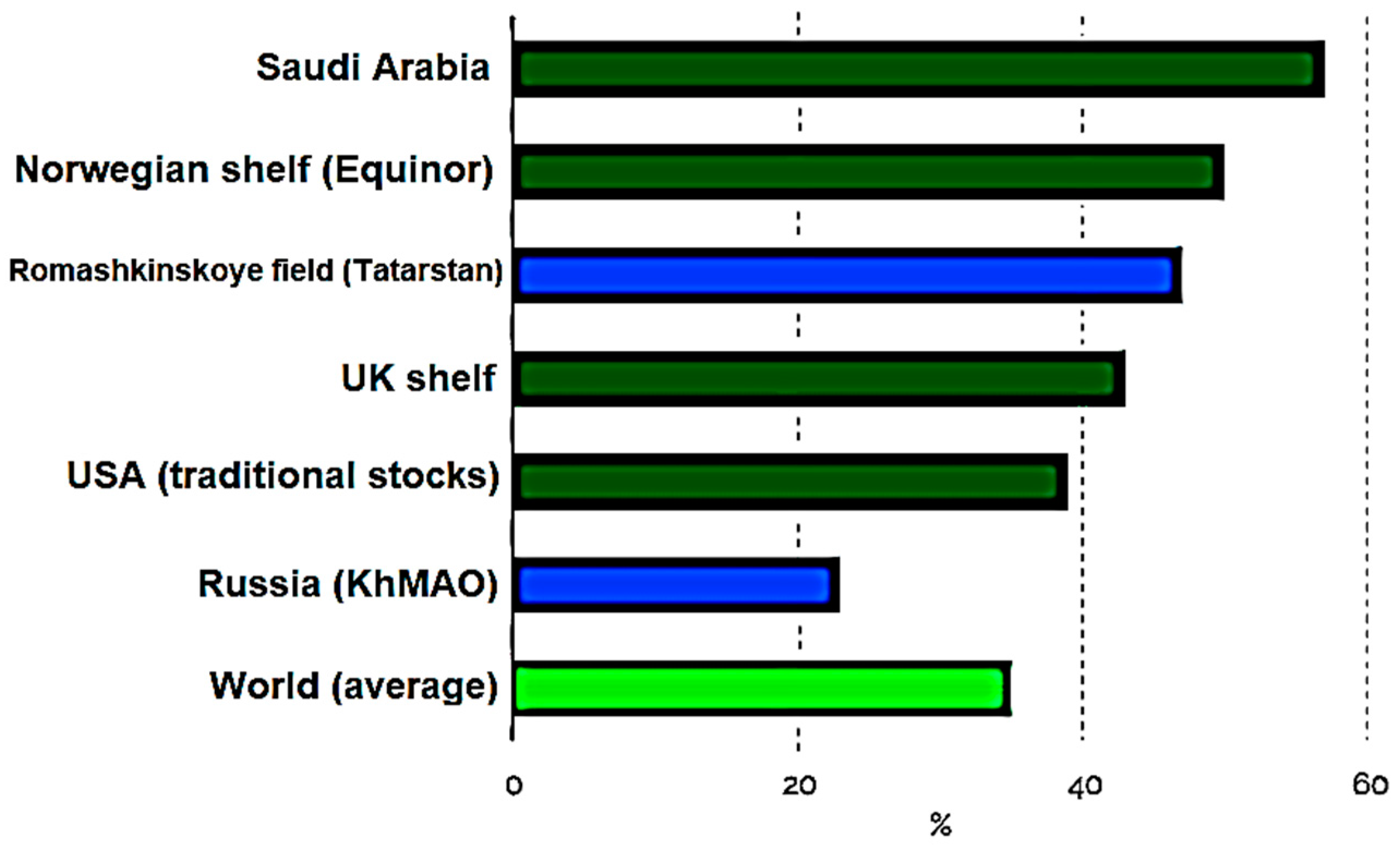
Figure 1. Average ORF by country of the world [8].
Therefore, even a small increase in it will make it possible to significantly increase the resource base without significant investments in the exploration and development of new projects. Thus, according to calculations of Shell, the growth of an oil recovery factor of only 1% in the world will increase the conventional oil reserves to 88 billion barrels, which is 2.5 times more than today is produced per year.
In the geological literature devoted to oil subjects, there are different understandings and interpretations of the term “natural reservoir”. The structure of natural reservoirs is determined by their type, the material composition of their constituent rocks, the type of void space of reservoir rocks and the aging of these rocks over the area.
All the strata composing the body of the massif are usually hydrodynamically connected but may be of different ages. The fluid reservoirs are strata or strata of rock salt, clay or sulfate rocks. Such a natural reservoir encompasses several tiers and may stand out in the volume of the entire formation.
The nature of the distribution of secondary minerals, their associations, and the number can be studied using traditional petrographic methods, including quantitative mineralogical counting of new formations in thin sections; the most typical features of minerals, their interchange and mineral associations either increase or decrease. Some clays are as highly porous as sandstones, but they are impermeable because their pore size is very small. The larger the pores, the higher the permeability. In general, there is no direct relationship between porosity and permeability, although rocks with low porosity (10–15%) usually have low permeability as well. If the permeability is low, oil will only ooze weakly from the rock and productivity will be less than economically viable. Therefore, it is difficult to recover oil from clays, although abundant signs of oil in them are found in many areas of the world.
Methods for recovering oil from clayey rocks are being developed. Prediction of changes in the reservoir properties of rocks during their subsequent burial can be made by statistical methods based on the study of physical and chemical processes that took place or on the results of quantitative petrographic studies, and each method has its limitations. The thickness of sand bodies, their area development and shape in plan, internal structure and nature of contacts with the surrounding strata are laid down by the sedimentation environment, which predetermines the reservoir volume and the well placement technique.
The shape (morphology) of a natural reservoir is determined by the ratio of reservoir rocks and cover rocks in the section and over the area. Variability of the productive formation shape is determined by its unequal thickness (total and effective), dissection, wedging of the whole formation and its constituent interlayers, and their lithological and facial replacement by impermeable differences. Formation natural reservoirs are reservoir beds bounded on a large territory at the top and bottom by impermeable rocks (fluids). Their thickness varies within a significant range (from 1–2 m to tens of m). In the lithological plan, they can be represented by both terrigenous and carbonate rocks; they may contain interlayers and interlayers of impermeable rocks in the reservoir bed. Formation natural reservoirs with lithologically wedging reservoirs are widely developed in the sediments of many geological systems. Reservoir wedging can occur in the case of monoclinal bedding of sedimentary formations in the direction of rock uplift.
2. Conventional and Unconventional Reservoirs
It is important to note that the distinction between traditional and non-traditional hydrocarbon resources is conditional in terms of a number of parameters. It is necessary to understand what sources of hydrocarbons create traditional and unconventional hydrocarbon deposits. A detailed consideration of the geological patterns of the formation of hydrocarbon accumulations shows that an understanding of these processes helps in the search for hydrocarbons (HC), assessing the number of hydrocarbons in deposits and methods for their extraction. If these strata gave their hydrocarbon potential to the reservoir with a tire, then an oil and gas field or a traditional hydrocarbon field was formed. At the same time, the deposit of unconventional shale gas disappeared. Accordingly, the presence of residual hydrocarbons in shale makes it possible to extract them using modern methods, calling them an unconventional source of hydrocarbons. In addition, there is an inflow of hydrogen and hydrocarbon gases from deep horizons of the earth’s crust and mantle. This flow can create both traditional and unconventional deposits. Non-traditional sources of hydrocarbons allow listing non-traditional sources of hydrocarbons. These are gas hydrates, coal methane, shale gas, tight reservoirs, and biogas. This ice-like solid is formed when hydrocarbons are introduced into the space between water molecules at high pressure and low temperature. For example, at a pressure of 30 atm and a temperature of 0 °C, in the presence of water and hydrocarbon gases, mainly methane, gas hydrates are formed in bottom sediments. As the temperature increases, a higher pressure is required to form gas hydrates. For example, in the Sea of Okhotsk, at a bottom water temperature of +2.4 °C, gas hydrates were found at a minimum depth of 386 m. At a shallower depth at this temperature, gas hydrate cannot be formed due to insufficient pressure. The gas hydrate, which contains mainly methane, is characterized by structure I and II. If hydrocarbons with a large size of propane molecules are present in the gas hydrate, structure II is formed. Why are gas hydrates of interest? They are an important object of geological research. In bottom sediments in the zone of stability of gas hydrates, the latter occurs in the form of layers, interlayers, and fragments. 1 cm3 of gas hydrate contains 170 cm3 of gas (hydrocarbons, methane). Gas hydrate plays a very important role in the geological history of the Earth and the formation of oil and gas deposits. The gas hydrate preserves hydrocarbons that migrate to the surface from oil and gas deposits, mantle and other sources. In a gas hydrate, hydrocarbon gases are not subject to microbial oxidation. The gas hydrate loosens the bottom sediments, penetrating into them, changing the bottom surface topography, and forming rises and dips in the upper layers of the bottom sediments, which is important to know when solving engineering geological problems and building offshore facilities. An important geological feature of gas hydrates is their impermeability. They are a good tire under which free gases accumulate. During periods of seismotectonic activations, this seal is disturbed by fault zones, through which gas (methane, heavy hydrocarbons) moves through the layers of the sedimentary stratum, partially filling the reservoir, forming deposits, and partially migrating in the form of a flow of bubbles into the water column. At the same time, the concentration of methane in water increases 100–1000 times and partially enters the atmosphere, which contributes to global climate change (warming). The formation of oil and gas deposits is interconnected with gas hydrates [7]. In the geological history of the Earth, there were periods of cooling and warming; the levels of the seas and oceans changed, which means that pressure and temperature were disturbed (the gas hydrate stability zone changed), and the gas hydrate contributed to the formation of hydrocarbon deposits. The second side of the importance of studying gas hydrates is that gas hydrates contain trillions of cubic meters of hydrocarbons that can be extracted as unconventional deposits. Currently, the extraction of hydrocarbons from gas hydrates, which are found in bottom sediments in the upper layers at a bottom depth of 1–10 m, has not yet reached commercial efficiency. The authors proposed one of the methods [8]. The difficulty lies in the fact that gas hydrates are mainly distributed in the bottom sediments of the seas, where it is difficult to extract hydrocarbons. However, it is important that gas hydrates are an indicator of the presence of hydrocarbons at depth; that is, they search for signs of oil and gas deposits. Traditional and unconventional hydrocarbon resources, gas hydrates and oil and gas deposits are gas hydrates that are found in the form of reservoirs in wells developed by conventional methods of operating oil and gas wells, with heating, pressure reduction and other methods.
Thus, it is necessary to understand in more detail what traditional and non-traditional sources of hydrocarbon production represent. It is not just about terminology. It must be understood that this is the same source of hydrocarbons. It is important to proceed from the history of the geological development of the studied region and basin in order to correctly assess the conditions for the formation of traditional and unconventional hydrocarbon deposits, the flow of hydrocarbons from the mantle, from the organic matter of shale, their mutual influence and accumulation in traditional reservoirs. All types of unconventional hydrocarbon sources: oil, gas hydrates, coal gas, coal gas shale gas, shale oil, biogas and tight reservoir gas, are all interconnected and create traditional oil and gas fields.
3. Enhanced Oil Recovery Methods Used for Intensification of Oil Production
3.1. Structure and Main Destination of Methods for Enhanced Oil Recovery (EOR)
In order to increase the economic efficiency of field development, reduce direct capital investments and maximize the use of reinvestment, the entire period of field development is usually divided into three main stages. In the first stage, the natural energy of the reservoir is used as much as possible for oil production (elastic energy, energy of dissolved gas, energy of marginal waters, gas cap, potential energy of gravitational forces). In the second stage, methods of maintaining reservoir pressure are implemented by pumping water or gas. These methods are called secondary. In the third stage, enhanced oil recovery methods (EOR) are used to improve the efficiency of field development. Five main groups can be distinguished among them:
-
Physical and chemical methods involve flooding with the use of active impurities (surfactants, polymers, alkalis, sulfuric acid, carbon dioxide, and micellar solutions);
-
Hydrodynamic methods allow intensifying the current oil production, increasing the degree of oil recovery, as well as reducing the volume of water pumped through the reservoirs and the current water cut of the produced fluid. For example, there is cyclic flooding, changing the direction of seepage flows, and forced fluid withdrawal;
-
Gas and water–gas methods are based on the injection of air into the reservoir and its transformation into effective displacing agents due to low-temperature in situ oxidation processes. As a result of low-temperature oxidation, a highly effective gas agent is produced directly in the reservoir, containing nitrogen, carbon dioxide and NGLs (broad fractions of light hydrocarbons). For example, these are water–gas cyclic impact and displacement of oil by high-pressure gas;
-
Thermal methods are used to stimulate the flow of oil and increase the productivity of production wells based on an artificial increase in temperature in their wellbore and bottom hole zone. Thermal EOR is used mainly in the production of high-viscosity paraffinic and resinous oils. Heating leads to oil liquefaction, melting the paraffin and resinous substances that have settled during the operation of wells on the walls, lifting pipes and in the bottom hole zone. For example, they include steam-cycling treatment, in situ combustion, use of water as a thermal solvent for oil;
-
Combined technologies represent a combination of the first four components.
According to their properties, the methods of enhanced oil recovery can be divided into groups: the first one increases the coefficient of oil displacement by water; the second one increases the sweep efficiency of the reservoir by flooding, and the third group increases both coefficients and hence the oil recovery factor as a whole.
Unlike MIP, enhanced oil recovery methods affect the development object or its part, thereby allowing the involvement in the development of residual, unrecovered oil reserves that cannot be produced with the designed waterflooding system. The practice has shown that the use of EOR is several times more expensive than conventional flooding, so the profitability of their use depends on the cost of the oil produced. EOR includes [9]:
-
physico-chemical methods using aqueous solutions: active impurities (surfactants (surfactants), polymers, micellar solutions, alkalis, acids), change or alignment of injectivity profiles (VPP);
-
hydrodynamic methods, including cyclic flooding, changing the direction of filtration flows, creating high injection pressures, forced fluid withdrawal (FOL), combined non-stationary flooding;
-
gas methods realizing the displacement of oil by high-pressure gas, water–gas treatment;
-
thermal methods using the displacement of oil by heat carriers (hot water, steam), in situ combustion;
-
other methods involve compaction of the good pattern, transition from one development system to another (local, selective flooding, creation of a block-closed system), hydraulic fracturing (HF), placement and operation of side and horizontal wells, microbiological, wave, and electromagnetic methods.
Enhanced oil recovery methods are based on the following changes in the physical characteristics and conditions of oil in the reservoir:
-
reduction of interfacial tension at the boundary of the oil-displacing agent;
-
decrease in the mobility ratio of the displaced and displacing fluids (due to a decrease in oil viscosity or a decrease in the mobility of the displacing agent);
-
redistribution of oil, water and gas in the reservoir in order to consolidate oil reserves.
4. Physical and Chemical Methods of Enhanced Oil Recovery
4.1. Displacement of Oil by Aqueous Solutions of Surface-Active Substances (Surfactants)
From the very name “surfactants”, it follows that adding them to the injected water changes the physical and chemical properties of the aqueous solution-the oil displacer, reduces the surface tension at the “water–oil” interface, increases the hydrophilicity of the surface of the pore channels, i.e., rock grains become more wetted by water [10]. There is an increase in the coefficients of oil displacement by the aqueous phase during forced displacement and capillary impregnation, in a change in the relative phase permeabilities of porous media [11][12]. This is caused by surfactant adsorption on the surfaces of pore channels.
4.2. Surfactant Adsorption
Adsorption is the process of precipitation of a surfactant from an aqueous solution and its settling on the surface of pore channels under the action of forces of intermolecular interaction.
Film oil covers the hydrophobic part of the pore surface of the formation in the form of a thin layer or in the form of adhering droplets held by adhesion forces. The work of the adhesion forces 𝑊𝑎
, required to remove film oil from a unit surface of pores into the aqueous phase that fills the pores, is determined by the Dupré or Dupré–Young equations [13]. It is better to wash the oil with water or solutions that wet the rock well.
The addition of surfactants to water leads to a change in the ratio of free surface energy values due to the adsorption processes of surfactants at interfacial interfaces. This process is largely determined by the specific surface of the collector and the adsorption activity of the surface of the porous medium [14].
4.3. Surfactant Compositions
Surfactants are chemical compounds capable of changing phase and energy interactions on various interfaces due to adsorption: they are liquid–air, liquid–solid, and oil–water. Surface activity, which many organic compounds can exhibit under certain conditions, is due to both the chemical structure, in particular, the amphiphilicity (polarity and polarizability) of their molecules, and external conditions. They are the nature of the medium and the contacting phases, surfactant concentration, and temperature [15].
According to the ionic characteristic, all surfactants are usually divided into two large groups: nonionic compounds, which do not dissociate into ions when dissolved in water, and ionic compounds. Depending on which ions determine the surface activity of ionogenic substances, they are usually divided into anionic (AS), cationic (SCS) and ampholytic. Anionic surfactants are more active in alkaline solutions, cationic surfactants in acidic ones, and ampholytic surfactants in both [16].
4.4. Displacement of Oil from the Reservoir by Polymer Solutions
The coefficient of mobility is the ratio of the phase permeability to the viscosity of the liquid. For oil and water, the mobility coefficients are as follows [17]:
Darcy’s law for water and oil has the form:
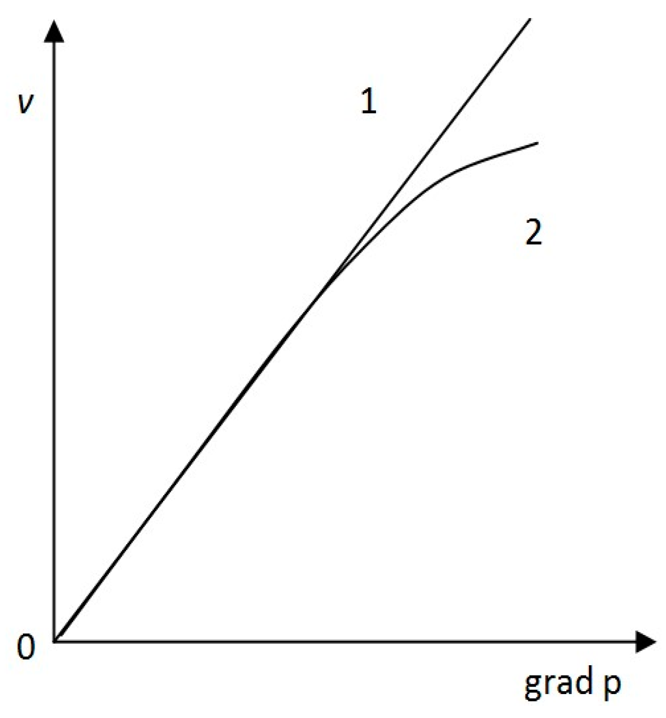
With an increase in the pressure gradient, the filtration rate of the polymer solution increases by a smaller amount than that when filtering pure water (Figure 2 [18]).
Figure 2. Dependence of the filtration rate of (1) Newtonian and (2) dilatant fluids on the pressure gradient [18].
4.5. Micellar-Polymer Flooding Method
The method of complex impact on the oil reservoir by pumping a mixture of surfactants, alcohols, oil solvents, an aqueous solution of PAA and water into it is called the micellar flooding method. When the concentration of surfactant in the solution is higher than the critical one for micellization, the surfactant is present in the solution in the form of clumps (micelles), which are capable of absorbing liquids constituting their internal phase [19]. At a high concentration of surfactants, together with oil and water, they form oil–water aggregates—micelles 10–5÷10–6 mm in size.
4.6. Change or Alignment of the Injectivity Profile (RWY)
To improve reservoir coverage by waterflooding, flow-diverting technologies are often used, which change the direction of the flow of injected fluids. This is achieved by increasing the filtration resistance of the flooded sections of the formation by pumping into it such reagents that form various plugging plugs in the washed zone when mixed with formation water. At the same time, a waterproofing screen is created in the highly water-cut interlayer, which deflects the flows of water injected into the reservoir into the oil-saturated layer, increasing the oil recovery factor [20]. Flow diverting technology is based on the injection of limited volumes of special reagents into injection wells, designed to reduce the permeability of highly permeable reservoir layers (up to their blocking) in order to equalize the good injectivity along the reservoir section and, thereby, create a more uniform displacement front and reduce water breakthroughs to producing well. Flow-diverting technologies allow the creation of strong barriers to water filtration and increase oil recovery by increasing sweep efficiency. These technologies are used at the final stage of development or when solving problems related to repair and insulation works [20].
4.7. Selection of Sites and Wells for the Application of Technology for Increasing the Injectivity Profile
The priority prerequisites for the application of this technology in areas with a significant degree of depletion of reserves and high water cuts are [21]:
-
The presence of a pronounced geological filtration heterogeneity of the reservoir section (a prerequisite for the advanced development of reserves in individual interlayers). First of all, areas with the most pronounced heterogeneity are processed.
-
Correspondence of the degree of recovery of oil reserves to the water cut of the products: the lower the correspondence, the need for work is dictated first (this indicates the presence of pinched residual recoverable reserves).
-
The ratio of the degree of pumping (as a percentage of the pore volume of the site) and the selection from the NIH (the efficiency of the RPM system). The larger this ratio, the lower the current efficiency of the reservoir pressure-maintenance system and the more volumes of water are injected and extracted without doing useful work on the frontal oil displacement. This fact also indicates the relative value of artificially pinched residual recoverable reserves. Therefore, first of all, attention should be paid to areas that have the highest ratio of pumping and selection from NIH.
-
Ceteris paribus, the sections of the production facility corresponding to the Kazemi model are processed first. That is, they have high and low permeability interlayers.
-
Under conditions of a homogeneous geological structure, for example, in monolithic deposits, the permeabilities determined for production and injection wells are compared, respectively, according to pressure build-up and efficiency.
4.8. Hydrodynamic Methods for Enhanced Oil Recovery
Hydrodynamic methods are used at the third and fourth stages of the development of production facilities; they are secondary methods of oil production and are among the most economical methods of enhanced oil recovery. Hydrodynamic EORs are subdivided into changing the direction of filtration flows, cyclic waterflooding, and forced fluid withdrawal. Their combined application should be defined as combined non-stationary waterflooding since each of these methods is based on non-stationary fluid filtration [22].
4.8.1. Changing the Direction of Filtration Flows
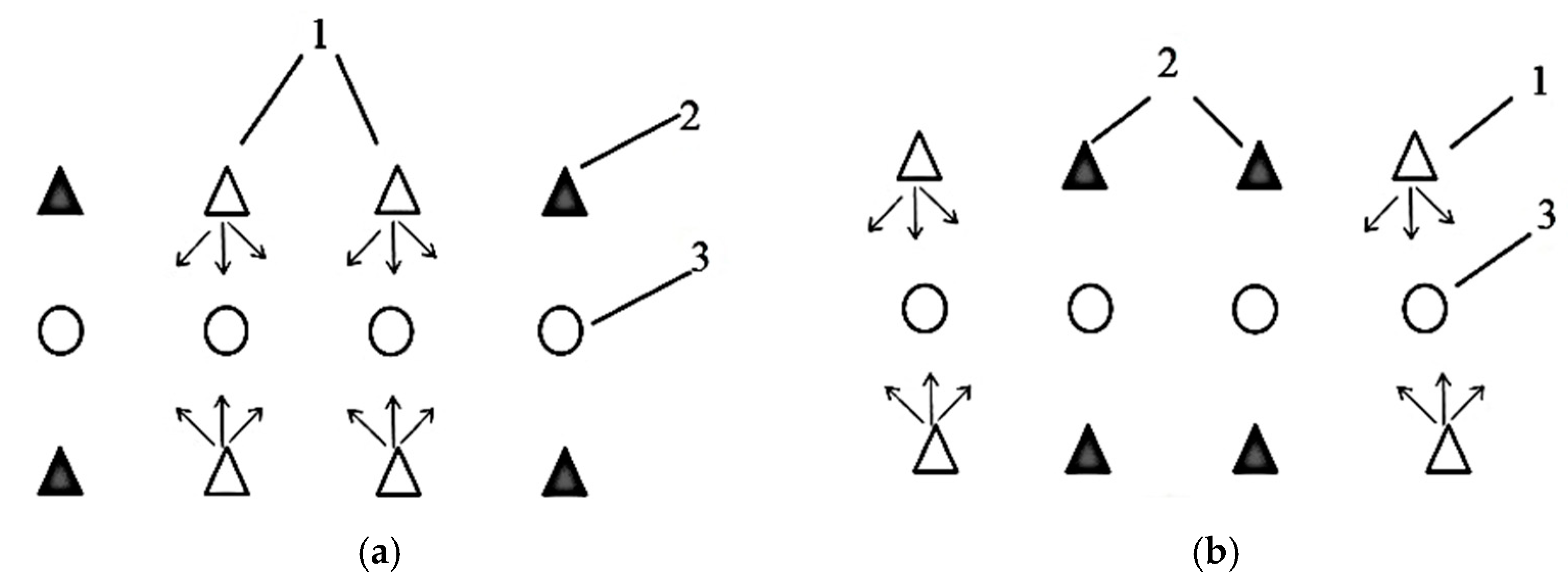
The technology of the method lies in the fact that at the production facility, the injection of water into injection wells periodically changes [23]. In the first stage, some injection wells are working; others are not working (Figure 3a). In the second stage, injection into these wells is stopped and transferred to others (Figure 3b). As a result, the direction of filtration flows changes. Figure 3 shows one of the possible schemes for changing filtration flows.
Figure 3. Scheme of changing the direction of filtration flows: (a) operation of the first group of injection wells; (b) shutdown of the first group of wells, operation of the second group of injection wells, 1—working injection wells, 2—idle injection wells, 3—production wells [24].
4.8.2. Forced Liquid Withdrawal (FOL)
Forced fluid withdrawal consists of a gradual increase in production well production rates. The essence of the method is to create high-pressure gradients by increasing the drawdowns, therefore, reducing the bottom hole pressure in production wells and increasing the injection pressure. At the same time, in heterogeneous, heavily watered reservoirs, residual oil pillars, lenses, dead-end and stagnant zones, and low-permeability interlayers are involved in development [25]. Method applicability conditions are as follows:
-
Water cut of products of not less than 90–95% (beginning of the final stage of development);
-
High well productivity factors at the beginning of the operation;
-
when the bottom hole pressure decreases, the reservoir is stable (does not collapse), and the discharge pressure should not exceed the tensile strength of the rock;
-
The casing is in good condition; there are no water flows from other horizons;
-
The throughput of the system for collecting and preparing products is sufficient for the use of FOL.
4.8.3. Cyclic Flooding
The main criteria for the application of cyclic waterflooding are as follows [21]:
-
The presence of layered heterogeneous permeability or fractured porous hydrophilic reservoirs;
-
High residual oil saturation of low-permeability interlayers;
-
The technical and technological possibility of creating a high amplitude of pressure fluctuations (flow rates), which can reach 0.5–0.7 of the average pressure drop between injection and production wells (average flow rate).
4.8.4. Combined Non-Stationary Flooding
The considered technologies are changes in the direction of filtration flows and cyclic waterflooding; FLC is a non-stationary physical process. Pressures and pressure gradients depend on time. The use of cyclic waterflooding is based on the existence of a hydrodynamic connection between interlayers of different permeability. The extraction of oil from a low-permeability reservoir, the flow of oil in the second half-cycle from OP to EP, does not formally increase the sweep efficiency. However, it allows involving low-permeability differences in the effective thickness of the opened interval in the development [21]. Therefore, the thickness coverage ratio increases. Over time, the amount of oil flowing from OR to WP decreases, and the sweep efficiency also decreases. However, it allows involving low-permeability differences in the effective thickness of the opened interval into the development. Therefore, the thickness coverage ratio increases. Over time, the amount of oil flowing from OR to WP decreases, and the sweep efficiency also decreases. However, it allows involving low-permeability differences in the effective thickness of the opened interval in the development [26].
5. Gas and Water–Gas EOR
5.1. Displacement of Oil from the Reservoir by Carbon Dioxide (CO2)
To displace oil from the reservoir, carbon dioxide CO2 can be used, which mixes with oil at a temperature of 300–310 °K and pressure above 10 MPa. However, resins and asphaltenes contained in the oil are slightly soluble in CO2 and may precipitate. Critical values are CO2 P = 7.38 MPa, T = 305 °K. For complete solubility of CO2, it is necessary to increase the temperature and pressure above critical values, for example, P = 30 MPa, T = 360 °K [27].
Another way to use CO2 is as follows. Water is pumped into the formation with carbon dioxide dissolved in it (carbonized water). Due to the greater chemical “affinity” of oil and CO2, upon contact with carbonized oil water, CO2 molecules diffuse, loosen heavy oil films on the surface of rock grains, and make these films mobile, which leads to an increase in the amount of oil to be recovered [28].
5.2. Displacement of Oil by Hydrocarbon Gases
Currently, much attention is paid to the utilization of associated petroleum gas. One of the ways to use associated gas is to use it as a reagent injected into injection wells in order to increase the oil displacement efficiency [29].
To increase oil recovery, the following gases are used: dry hydrocarbon gas, high-pressure gas, enriched gas and gas–water (water–gas) mixture. When using liquefied hydrocarbon gases and other liquid hydrocarbon solvents as displacing agents, another problem arises in extracting the solvent remaining there, the price of which can significantly exceed the cost of oil [30].
Oil displacement by the reagent can be immiscible or miscible (without the existence of a phase boundary). The miscibility of gas with oil in reservoir conditions is achieved only in the case of light oils (the density of degassed oil is less than 800 kg/m3). The injection pressure of dry hydrocarbon gas is 25 MPa or more, and the pressure of enriched gas is 15–20 MPa. When mixing (dissolving) gas with oil, the viscosity of oil decreases, the mobility of oil increases, including flow rates (Dupuy’s formula [31]), and, ultimately, oil recovery.
5.3. Water–Gas Cyclic Impact
The technology of cyclic water–gas treatment consists of the fact that gas and water are injected into the reservoir alternately by rims or simultaneously in a mixture into the same or separate injection wells [32].
Physically, the oil displacement mechanism is as follows. Water fills small pores and narrows the pore channels, thereby increasing the sweep efficiency. The gas injected into the reservoir, due to its greater mobility, occupies large pores, and the upper part of the reservoir partially dissolves in oil, increasing its mobility and thereby increasing the displacement efficiency. Thus, gas increases one of the factors of the oil recovery factor, and water increases the other [33].
Joint displacement of oil from heterogeneous reservoirs by water and gas is more effective for ultimate oil recovery than the separate displacement of oil only by water or gas. By choosing the optimal operating mode, reservoir recovery can be increased by 7–15% compared to conventional waterflooding. The main condition for the optimality of the water–gas treatment process is to ensure a uniform distribution of the injected gas over the water-flooded volume of the reservoir, in which there is a simultaneous breakthrough of gas and water into production wells. The duration of injection cycles for each agent is 10–30 days [34][35]. By choosing the optimal operating mode, reservoir recovery can be increased by 7–15% compared to conventional waterflooding. The main condition for the optimality of the water–gas treatment process is to ensure a uniform distribution of the injected gas over the water-flooded volume of the reservoir, in which there is a simultaneous breakthrough of gas and water into production wells. The duration of injection cycles for each agent is 10–30 days [34].
6. Thermal Methods of Enhanced Oil Recovery
6.1. Physical Processes Occurring When Oil Is Displaced by Heat Carriers
The initial value of reservoir temperature and its distribution in the reservoir is determined by the geothermal conditions in which the field is located. Typically, reservoir temperature follows a geothermal gradient. During the development of the field, the reservoir temperature may change. Thus, the water injected into the reservoir has a different temperature. Processes associated with the release or absorption of heat occur in the reservoir. The temperature change will occur due to the hydraulic resistance of the filtering fluids due to the Joule–Thomson effect [36].
The distribution of reservoir temperature and its change is called the temperature regime. The change in the temperature regime occurs mainly due to thermal conductivity and convection (warm fluids have a lower density, they are lighter) [37][38].
6.2. Displacement of Oil from the Reservoir by Hot Water and Steam
Hot water and steam, otherwise coolants, are produced in high-pressure steam generators (boilers) and pumped into the formation through injection wells of a special design and with special equipment designed to operate at high temperatures [39]. The disadvantage of using surface steam generators is large losses of heat (temperature) in surface communications and in the wellbore. When the coolant moves along the formation, heat losses occur through the roof and bottom of the formation. To reduce heat loss, layers with a thickness of more than 6 m are chosen, and areal grids of wells are used at a distance of up to 100–200 m between injection and production wells. The perforation interval is chosen in the middle part of the formation; the pipes are insulated, and the steam generator is brought as close as possible to the wells [40].
6.3. Thermal Rim Method
According to this technology, instead of continuous injection of the coolant after its penetration into the formation, after a certain time, water is pumped at the formation temperature. A heated region (thermal rim) is created in the reservoir, which moves from the injection well to the production wells under the influence of cold water injection into the reservoir [41].
In this case, when oil is displaced by a thermal rim, three displacement fronts are formed in the reservoir: 1—hydrodynamic-displacement of unheated cold oil by water; 2—thermal front-displacement of heated oil of low viscosity with hot water; 3—hot oil displacement front with cold water. Moreover, the 3rd front of hot oil displacement by cold water will lag behind the previous two. The heat of the hot oil will be transferred to the cold water, i.e., the reverse process of heat transfer will take place in the direction of the injection well. The viscosity of the displaced oil will increase, and the mobility coefficient will decrease. Unrecovered oil reserves will remain in the reservoir [42].
7. Combined Technologies for Enhanced Oil Recovery in Deposits with High-Viscosity Oils
7.1. Thermopolymer Formation Stimulation (TPV)
The TST technology is based on the injection of a PAA solution with a concentration of 0.05–0.1%, heated to a temperature of 90–950 °C, into the reservoir [43]. The viscosity of a heated aqueous solution of polyacrylamide is 1.5–2 mPa∙s. The viscosity of oil in the fracture system decreases, and part of the hot solution, mainly hot water, impregnates the blocks, improves the hydrophilicity of the rock, increases the mobility of the oil, and thereby leads to its displacement.
7.2. Steam-Cycling Treatment of Production Wells
Steam-cycling treatment of production wells refers to the methods of intensification of inflow (MIP). During steam cycling treatments, steam is pumped into a production well for 15–20 days in a volume of 100–300 tons per 1 m of formation thickness [44]. Then the well is closed for 10–15 days to redistribute heat and countercurrent capillary displacement of oil from low-permeability interlayers (LP) into a high-permeability interlayer. Further, the well is operated until the maximum profitable production rate is reached within 2–3 months.
The physical essence of the process is as follows: steam liquefies high-viscosity oil and increases the oil mobility coefficient [45]. Depending on the change in temperature and pressure, the steam first passes into a two-phase state of steam-water, then after condensation, into hot water, which, invading low-permeability layers, reduces the viscosity of the oil located there. After the well is stopped, as well as during cyclic waterflooding, water begins to displace oil from the OR to the WP [46]. At the third stage of the good operation cycle, the pressure in the bottom hole zone drops, and the oil recovery increases due to its greater mobility. Thus, the technology implementation cycle consists of three stages.
7.3. In Situ Combustion
In situ, combustion (IG) is based on the ability of hydrocarbons (in this case, oil) to chemically react with oxygen. As a result of combustion, a large amount of heat is released in the reservoir; the temperature rises, and the physical properties of reservoir fluids and rock change. Unlike other thermal methods of enhanced oil recovery, HSV eliminates technical problems and heat losses that occur when it is generated on the surface and delivered to the reservoir by injecting heat carriers into it [47][48]. The call of combustion is carried out at the bottom of the well—the incendiary. An oxidizing agent (usually air) is pumped into the injection well while simultaneously heating the bottom hole formation zone using a downhole electric heater, gas burner, incendiary chemical mixtures, etc.
7.4. Dry In Situ Combustion
In dry in situ combustion, only air is injected to sustain combustion. The main part of the heat generated in the reservoir (80% or more) remains in the area behind the combustion front and is gradually dissipated into the rocks surrounding the reservoir. This heat has a certain positive effect on the process of displacement from adjacent parts of the reservoir not covered by combustion [49][50].
It has been established that in the case of maintaining in situ combustion by injecting only a gaseous oxidizer (air) into the formation, heat loss from the rock heated as a result of combustion occurs more slowly due to the low heat capacity of the airflow than when the rock is heated by a moving combustion front. When the combustion front moves, a part of the oil that remains in the reservoir after its displacement by combustion gases, water vapor, water, and evaporated light fractions of oil ahead of the combustion front is consumed as fuel [51].
7.5. Wet In Situ Combustion
The combination of in situ combustion and flooding is called wet in situ combustion. The essence of wet combustion lies in the fact that water injected along with the air in certain quantities, evaporating in the vicinity of the combustion front, transfers the generated heat to the area in front of it, as a result of which extensive heating zones develop in this area, formed by zones of saturated steam and condensed hot water. The process of in situ steam generation is one of the most important distinguishing features of the wet combustion process, which determines the mechanism of oil displacement from reservoirs [37][52][53].
The values of the ratios of the volumes of water and air injected into the reservoir are within the limits of 1–5 m3 of water per 1000 m3 of air (under normal conditions), i.e., the water–air factor should be (1–5)∙10–3 m3. The specific values of the water–air factor are determined by various geological and field conditions for the implementation of the process. However, with an increase in oil density and viscosity (more precisely, with an increase in coke concentration), the required water–air factor decreases [54].
The combustion front is characterized by the highest temperature—here, it reaches 370 °C and above. As the combustion front moves in the reservoir, several characteristic, distinct temperature zones are formed [55]. In the scorched region behind the combustion front, two temperature zones are distinguished. In the transition zone, the temperature changes from the temperature of the injected working agents (water and air) to the evaporation temperature of the injected water. Directly adjacent to the combustion front is a zone of superheated steam formed as a result of the evaporation of water injected together with air in the rock, heated to a high temperature by the combustion front moving ahead [56].
Heat transfer to the area ahead of the combustion front is carried out during wet combustion mainly by convective transfer by flows of evaporated injected water and combustion products, as well as by heat conduction. As a result, several temperature zones are formed ahead of the combustion front [57]. A zone directly adjacent to the combustion front has superheated steam, within which the temperature drops from the temperature of the combustion front to the temperature of condensation (evaporation) of the steam. The size of this zone is relatively small because heat losses in the rocks surrounding the reservoir led to rapid cooling of the gaseous water vapors filtered here and combustion products, which are characterized by low heat capacity [58]. The main share of the heat transferred to the area ahead of the combustion front is concentrated in the zone of saturated steam—the zone of the steam plateau. There is heat loss to the surrounding rocks, accompanied by steam condensation in the transitional temperature zone. A hot water zone formed as a result of the complete condensation of saturated steam. The temperature in the saturated steam zone depends mainly on the level of reservoir pressure, taking into account the proportion of steam in the gas flow. Usually, within this zone, it varies insignificantly and is approximately 80–90% of the saturated vapor temperature [59]. The temperature in the transition zone varies from the steam condensation temperature to the initial reservoir temperature [60].
7.6. The Method of Thermal Gas Exposure
The method of thermal gas exposure (TGT) refers to thermal methods [61]. It is used in light oil fields with elevated temperatures above 650 °C and high reservoir pressures; similarly to in situ combustion, nitrogen, carbon dioxide, and light oil fractions act as displacing gaseous agents that mix with oil and provide an increase in its mobility. This contributes to an increase in the oil recovery factor, especially when developing deposits with hard-to-recover reserves [62].
8. Other Methods of Enhanced Oil Recovery
8.1. Hydraulic Fracturing (HF)
One of the commonly used methods of enhanced oil recovery is hydraulic fracturing. Hydraulic fracturing technology and well development after hydraulic fracturing are discussed in detail in [63][64].
We consider the process of crack formation. It is known from continuum mechanics that in an elastic medium, a crack is formed in the plane of the highest normal stress, that is, in the plane in the direction of the rock stress [43]. Therefore, the crack is vertical. It propagates in the direction of the minimum normal stress, that is, in the direction radial from the well.
The choice of a good operation mode is determined by the results of hydrodynamic studies of wells after hydraulic fracturing. The performance of the ESP unit size should correspond to the good productivity factor determined after hydraulic fracturing [65].
The fracture created in the reservoir is filled with proppant, which does not allow it to close. Thus, a two-capacitive system formation–fracture is created in the reservoir. A fracture filled with proppant is a fictitious reservoir since the diameters of the proppant particles are the same [66].
8.2. Operation of Wells with Horizontal Completion
The development of engineering, technology and new scientific methods in drilling contributed to the construction and operation of horizontal wells [67]. In the literature, an incorrect definition of such wells is used: horizontal wells (HW), implying that only the horizontal part of the well that has penetrated the productive formation is in operation. A large number of works have been devoted to determining the mining capabilities of HS. There are several hydrodynamic models that describe the flow of fluid from the reservoir to the horizontal part of the well, the length of which can reach 600 m or more. As a rule, horizontal wells are used to extract oil from low-permeability differences that are not involved in development [68][69][70].
8.3. Acoustic Methods
According to the technology of their use, acoustic methods can be divided into MIP and EOR. The former has an impact on the bottom hole zone, improving reservoir properties and well productivity. The latter affects the element, part of the production facility, involving the development of uncovered areas and capillary-retained oil [71]. Recently, the development of technology has allowed various technologies to aim at the development and improvement of acoustic methods of influencing the BFZ.
9. World Experience in Using MIP and EOR
As it was presented, in the modern world, often all geological and technical measures (GTO) at wells can be attributed to EOR [72].
After analyzing a number of publications [73][74][75], the authors came to the conclusion that today only, less than 5% of the world’s oil production is accounted for by projects to increase oil recovery by tertiary methods. At the same time, EOR is one of the methods of oil production that increases the productivity of oil wells. It is carried out with artificial maintenance of reservoir energy or artificial change in the physical and chemical properties of oil) [76]. Annual production through the use of such methods in the world is estimated at about 150 million tons. Additionally, with the help of EOR, you can obtain much more, hundreds of billions of barrels of oil [77].
The same can be said about the injection of hydrocarbon gases, which is EOR only in cases of targeted oil displacement through the reservoir, and the usual injection into the gas cap through single wells to maintain reservoir pressure or utilize excess associated gas has always been a secondary development method, which is quite natural from physical principles [78].
Enhanced oil recovery (EOR) technology enhances oil production from mature and aged oil fields by almost 10 to 20 percent when compared to conventional oil extraction methods. Mature wells are those oil reserves where production has reached its peak and have started to decline to owe to poor permeability or exhibiting heavy oil. Technically, EOR increases the permeability of the reservoir so that hydrocarbons can flow through the pathways easily and into the targeting-producing well.
Today, such boundary definitions have become vague, largely due to opportunistic considerations, and many authors allow free terminology and definitions. For this reason (different positions towards the EOR classification), different statistical sources contain radically different data on the number of EOR projects and the volume of oil production in them [79].
In general, it can be stated that the general trend is an increase in the share of EOR gas projects, moreover, due to the use of carbon dioxide injection technologies while reducing projects for the injection of other gases [80]. At the same time, almost all growth was provided by the development of CO2 projects in the USA, the number of which reached 133. In general, it should be noted that the share of EOR projects in the USA (about 220) is exceptionally large and amounts to 60% of the global number of operating EORs in the world [81].
Differences in estimates of the number of EOR projects are primarily associated with different approaches to projects for the production of heavy (heavy oil) and extra-heavy (extra-heavy oil) oil, as well as with the allocation of production due to thermal technologies from all heavy oil production in the project (often all production, including the stage of “cold” production by horizontal wells, is attributed to EOR) [82].
A conservative assessment implies the exclusion of projects with extra-viscous oil (density less than 10 °API, which is directly indicated in the primary sources of publications), considering them as a separate category of hydrocarbons together with bitumen, more strict consideration of additional production in projects of heavy oil and gas methods [83].
The share distribution of oil production volumes due to different EOR groups differs from the structure of the number of EOR projects; thermal EOR continues to play the first role, although there is a downward trend [84]. The share of production through chemical technologies is growing noticeably, reaching 17–19%, significantly exceeding their weight share in the number of projects. This is due to the large-scale implementation of polymer and ASP flooding in China [85].
In technological terms, the unrealized potential of EOR in all oil-producing countries is large. However, the general situation with EOR in the world indicates that in the context of globalization of the economy, and even more so at the time of the transformation of the world economy (multi-vector development of the fuel and energy complex, “energy turn”), EOR has no real prospects for large-scale development. First of all, due to large initial capital investments and long payback periods for projects, moreover, with increased technological risks of errors in forecasting the achieved levels of oil production. Statements about the need for special economic mechanisms for the implementation of EOR technologies have become commonplace. However, specific and effective solutions have not been developed or adopted in almost any country in the world today, perhaps with the exception of China [86].
It is also important to note that over the past thirty years, there have been no fundamental successes in the development of EOR technologies in the world. All technological foundations of EOR are known, and it can be argued that there is only some modernizing development of them “in breadth” towards an evolutionary expansion of the conditions of applicability in terms of temperature and permeability of the formation, in terms of salinity of formation water. This is determined by the immutability of the scientific foundations of EOR and the lack of new fundamental research on capillary—chemical and rheological—in situ processes of oil displacement.
References
- Adams, K.; Kohlmeier, M.; Powell, M.; Zeisel, S. Nutrition in Medicine: Nutrition Education for Medical Students and Residents. Nutr. Clin. Pract. 2010, 25, 471–480.
- Kutergina, G.; Yapparov, E. The impact of integrated modelling on the technical and economic indicators of the oil production process. IOP Conf. Ser. Mater. Sci. Eng. 2020, 873, 012024.
- Adasani, A.; Bai, B. Analysis of EOR projects and updated screening criteria. J. Pet. Sci. Eng. 2011, 79, 10–24.
- Fritzsche, S.; Billig, S.; Rynek, R.; Abburi, R.; Tarakhovskaya, E.; Leuner, O.; Frolov, A.; Birkemeyer, C. Derivatization of Methylglyoxal for LC-ESI-MS Analysis—Stability and Relative Sensitivity of Different Derivatives. Molecules 2018, 23, 2994.
- Shchurov, N.I.; Dedov, S.I.; Malozyomov, B.V.; Shtang, A.A.; Andriashin, S.N.; Martyushev, N.V.; Klyuev, R.V. Degradation of Lithium-Ion Batteries in an Electric Transport Complex. Energies 2021, 14, 8072.
- Vertakova, Y.T.; Polozhentseva, Y.; Zvyagintsev, G. Prospects for development of hydrocarbon raw materials resources reproduction. IOP Conf. Ser. Earth Environ. Sci. 2017, 87, 092031.
- Martyushev, N.V.; Malozyomov, B.V.; Sorokova, S.N.; Efremenkov, E.A.; Qi, M. Mathematical Modeling the Performance of an Electric Vehicle Considering Various Driving Cycles. Mathematics 2023, 11, 2586.
- Lavenburg, V.M.; Rosentrater, K.A.; Jung, S. Extraction Methods of Oils and Phytochemicals from Seeds and Their Environmental and Economic Impacts. Processes 2021, 9, 1839.
- Khudaiberdiev, A.; Kosianov, P. Integrated physical enhanced recovery method for high-viscosity oil reservoirs. E3S Web Conf. 2021, 244, 09012.
- Zemenkova, M.; Kuzina, O.; Shabarov, A. Oil displacement by aqueous solutions of surfactants at various temperatures. IOP Conf. Ser. Mater. Sci. Eng. 2019, 663, 012003.
- Ahmed, B.; Amin, S.H.; Roozbeh, R. A review of fluid displacement mechanisms in surfactant-based chemical enhanced oil recovery processes: Analyses of key influencing factors. Pet. Sci. 2022, 19, 1211–1235.
- Holmberg, K.; Jonsson, B.; Kronberg, B.; Lindman, B. Surfactants and Polymers in Aqueous Solution; John Wiley & Sons, Ltd.: Hoboken, NJ, USA, 2002; ISBN 0-471-49883-1.
- Nimibofa, A.; Augustus, N.E.; Donbebe, W. Modelling and Interpretation of Adsorption Isotherms. J. Chem. 2017, 2017, 3039817.
- Al-Yaari, A.; Ching, D.L.C.; Sakidin, H.; Muthuvalu, M.S.; Zafar, M.; Alyousifi, Y.; Saeed, A.A.H.; Bilad, M.R. Thermophysical Properties of Nanofluid in Two-Phase Fluid Flow through a Porous Rectangular Medium for Enhanced Oil Recovery. Nanomaterials 2022, 12, 1011.
- Bjerk, T.R.; Severino, P.; Jain, S.; Marques, C.; Silva, A.M.; Pashirova, T.; Souto, E.B. Biosurfactants: Properties and Applications in Drug Delivery, Biotechnology and Ecotoxicology. Bioengineering 2021, 8, 115.
- Sun, X.; Liu, J.; Dai, X.; Wang, X.; Yapanto, L.M.; Zekiy, A.O. On the application of surfactant and water alternating gas (SAG/WAG) injection to improve oil recovery in tight reservoirs. Energy Rep. 2021, 7, 2452–2459.
- Salmo, I.C.; Sorbie, K.S.; Skauge, A. The Impact of Rheology on Viscous Oil Displacement by Polymers Analyzed by Pore-Scale Network Modelling. Polymers 2021, 13, 1259.
- Zaitsev, M.V.; Mikhailov, N.N.; Tumanova, E.S. Non-linear filtration models and the effect of nonlinearity parameters on flow rates in low-permeability reservoirs. Georesursy=Georesources 2021, 23, 44–50.
- Abuhasel, K.; Kchaou, M.; Alquraish, M.; Munusamy, Y.; Jeng, Y.T. Oily Wastewater Treatment: Overview of Conventional and Modern Methods, Challenges, and Future Opportunities. Water 2021, 13, 980.
- Fedorov, K.; Shevelev, A.; Gilmanov, A.; Arzhylovskiy, A.; Anuriev, D.; Vydysh, I.; Morozovskiy, N. Injection of Gelling Systems to a Layered Reservoir for Conformance Improvement. Gels 2022, 8, 621.
- Li, Y.; Zhou, F.; Xu, H.; Yu, G.; Yao, E.; Zhang, L.; Li, B. Comparative investigation of nanoparticles effect for enhanced oil recovery—Experimental and mechanistic study. IOP Conf. Ser. Earth Environ. Sci. 2022, 984, 12012.
- Korotenko, V.; Grachev, S.; Kushakova, N.; Leontiev, S.; Zaboeva, M.; Aleksandrov, M. On modeling of non-stationary two-phase filtration. IOP Conf. Ser. Earth Environ. Sci. 2018, 181, 012016.
- Zhizhin, M.; Matveev, A.; Ghosh, T.; Hsu, F.-C.; Howells, M.; Elvidge, C. Measuring Gas Flaring in Russia with Multispectral VIIRS Nightfire. Remote Sens. 2021, 13, 3078.
- Guodong, C.; Fulong, N.; Bin, D.; Tong, L.; Qiucheng, Z. Particle migration and formation damage during geothermal exploitation from weakly consolidated sandstone reservoirs via water and CO2 recycling. Energy 2022, 240, 122507.
- Liang, X.; Pengcheng, L.; Yun, Z. Development and Research Status of Heavy Oil Enhanced Oil Recovery. Geofluids 2022, 13, 5015045.
- Sun, L.; Li, B.; Jiang, H.; Li, Y.; Jiao, Y. An Injectivity Evaluation Model of Polymer Flooding in Offshore Multilayer Reservoir. Energies 2019, 12, 1444.
- Akpabio, J.; Ifeanyichukwu, C.; Isehunwa, S. Improved Oil Recovery by Carbon Dioxide Flooding. Int. J. Eng. Technol. 2014, 4, 1–6.
- Goharzadeh, A.; Fatt, Y.Y. Combined effect of silica nanofluid and wettability on enhanced oil recovery process. J. Pet. Sci. Eng. 2022, 215, 110663.
- Alagorni, A.H.; Yaacob, Z.B.; Abdurahman, H. Nour An Overview of Oil Production Stages: Enhanced Oil Recovery Techniques and Nitrogen Injection. Int. J. Environ. Sci. Dev. 2015, 6, 693.
- Morenov, V.; Leusheva, E.; Buslaev, G.; Gudmestad, O.T. System of Comprehensive Energy-Efficient Utilization of Associated Petroleum Gas with Reduced Carbon Footprint in the Field Conditions. Energies 2020, 13, 4921.
- Arutyunov, V. Utilization of associated petroleum gas via small-scale power generation. Russ. J. Gen. Chem. 2012, 81, 2557–2563.
- Shokufe, A.; Nima, R.; Sohrab, Z. A comprehensive review on Enhanced Oil Recovery by Water Alternating Gas (WAG) injection. Fuel 2018, 227, 218–246.
- Pichtel, J. Oil and Gas Production Wastewater: Soil Contamination and Pollution Prevention. Appl. Environ. Soil Sci. 2016, 2016, 2707989.
- Mohammad, R.S.; Zhang, S.; Zhao, X.; Lu, S. An Experimental Study of Cyclic CO2-Injection Process in Unconventional Tight Oil Reservoirs. Oil Gas Res. 2018, 4, 150.
- Al-Asadi, A.; Arce, A.; Rodil, E.; Soto, A. Enhanced oil recovery with nanofluids based on aluminum oxide and 1-dodecyl-3-methylimidazolium chloride ionic liquid. J. Mol. Liq. 2022, 363, 119798.
- Sorokin, A.S.; Bolotov, A.V.; Nuriev, D.R.; Derevyanko, V.K.; Minkhanov, I.F.; Varfolomeev, M.A. Dynamic Criteria for Physical Modeling of Oil Displacement by Gas Injection. Processes 2022, 10, 2620.
- Wang, M.; Yang, S.; Li, J.; Zheng, Z.; Liu, Q.; Wen, J.; Zhang, Y. Pressure-sensitive characteristics of high-pour-point live oil and quantitative analysis of composition change. J. Pet. Sci. Eng. 2020, 193, 107430.
- Fay, J. Physical Processes in the Spread of Oil on a Water Surface. Int. Oil Spill Conf. Proc. 1971, 1971, 463–467.
- Malozyomov, B.V.; Martyushev, N.V.; Sorokova, S.N.; Efremenkov, E.A.; Qi, M. Mathematical Modeling of Mechanical Forces and Power Balance in Electromechanical Energy Converter. Mathematics 2023, 11, 2394.
- Dietrich, J. The Displacement of Heavy Oil from Diatomite Using Hot Water and Steam. In Proceedings of the SPE Improved Oil Recovery Symposium, Tulsa, OK, USA, 24–28 April 2010.
- Nurgalieva, K.S.; Saychenko, L.A.; Riazi, M. Improving the Efficiency of Oil and Gas Wells Complicated by the Formation of Asphalt–Resin–Paraffin Deposits. Energies 2021, 14, 6673.
- Poddubny, Y.A.; Poddubny, A.Y. Methods to increase oil return in the world: Today and possible tomorrow. Drill. Oil 2020, 12, 43–49.
- Zoveidavianpoor, M.; Samsuri, A.; Reza, S. Well Stimulation in Carbonate Reservoirs: The Needs and Superiority of Hydraulic Fracturing. Energy Sources Part A Recovery Util. Environ. Eff. 2013, 35, 92–98.
- Meng, X.; Hang, S.; Zhang, H.; Gao, F.; Gao, Y.; Li, X. Study of Water Huff-n-Puff in Low-Permeability Oil Reservoirs with Horizontal Fractures: A Case Study of Chang 6 Reservoir in Yanchang, China. Front. Earth Sci. 2022, 9, 824410.
- Li, S.; Wang, Z.; Han, R.; Wang, L.; Hu, Z. Experimental Study on the Cyclic Steam Stimulation Assisted by Flue Gas under Shallow Heavy-Oil Reservoir Conditions: Optimization of the Steam-Flue Gas Ratio. Front. Energy Res. 2020, 8, 599370.
- Sarmah, S.; Gogoi, S.B.; Jagatheesan, K.; Hazarika, K. Formulation of a combined low saline water and polymer flooding for enhanced oil recovery. Int. J. Ambient. Energy 2022, 43, 1089–1097.
- Ran, X. Nonlinear Percolation Theory for Ultralow-Permeability Reservoirs, Chapter 2. In Advanced Water Injection for Low Permeability Reservoirs; Ran, X., Ed.; Gulf Professional Publishing: Houston, TX, USA, 2013; pp. 51–113. ISBN 9780123970312.
- Fazlyeva, R.; Ursenbach, M.; Mallory, D.; Mehta, S.; Cheremisin, A.; Moore, G.; Spasennykh, M. In Situ Combustion of Heavy Oil within a Vuggy Carbonate Reservoir: Part I—Feasibility Study. Energies 2023, 16, 2233.
- Hu, X.; Li, M.; Peng, C.; Davarpanah, A. Hybrid Thermal-Chemical Enhanced Oil Recovery Methods; An Experimental Study for Tight Reservoirs. Symmetry 2020, 12, 947.
- Storey, B.M.; Worden, R.H.; McNamara, D.D. The Geoscience of In-Situ Combustion and High-Pressure Air Injection. Geosciences 2022, 12, 340.
- Nikolova, C.; Gutierrez, T. Use of Microorganisms in the Recovery of Oil from Recalcitrant Oil Reservoirs: Current State of Knowledge, Technological Advances and Future Perspectives. Front. Microbiol. 2020, 10, 2996.
- Deniz-Paker, M.; Cinar, M. Investigation of the combustion characteristics of Bati Raman oil with sand. J. Pet. Sci. Eng. 2017, 157, 793–805.
- Huang, X.; Wang, Y.; Long, Y.; Liu, J.; Zheng, H.; Nie, W.; Han, H. Characteristics of Core-Shell Polymeric Nanoparticles Dispersion System in Porous Media. Polymers 2022, 14, 1803.
- Hu, B.; Gu, Z.; Zhou, C.; Wang, L.; Huang, C.; Su, J. Investigation of the Effect of Capillary Barrier on Water—Oil Movement in Water Flooding. Appl. Sci. 2022, 12, 6285.
- Sakthivel, S.; Zhou, X.; Giannelis, E.P.; Kanj, M.Y. Carbon nanodots for enhanced oil recovery in carbonate reservoirs. Energy Rep. 2021, 7, 8943–8959.
- Bashir, A.; Sharifi Haddad, A.; Rafati, R. Nanoparticle/polymer-enhanced alpha olefin sulfonate solution for foam generation in the presence of oil phase at high temperature conditions. Colloid. Surf. Physicochem. Eng. Aspect. 2019, 582, 123875.
- Wu, Y.; Zhang, J.; Dong, S.; Li, Y.; Slany, M.; Chen, G. Use of Betaine-Based Gel and Its Potential Application in Enhanced Oil Recovery. Gels 2022, 8, 351.
- Wei, B.; Tian, Q.T.; Mao, R.X.; Xue, Y.; Wen, Y.B.; Pu, W.F. Application and prospect of nano-cellulose materials in oil and gas field development. Pet. Geol. Recovery Effic. 2020, 27, 98–104.
- Ismail, N.B.; Hascakir, B. Impact of asphaltenes and clay interaction on in-situ combustion performance. Fuel 2020, 268, 117358.
- Berna, H.; Ross, C.M.; Castanier, L.M.; Kovscek, A.R. Fuel formation and conversion during in-situ combustion of crude oil. SPE J. 2013, 18, 1217–1228.
- Mukhametdinova, A.; Mikhailova, P.; Kozlova, E.; Karamov, T.; Baluev, A.; Cheremisin, A. Effect of Thermal Exposure on Oil Shale Saturation and Reservoir Properties. Appl. Sci. 2020, 10, 9065.
- Isah, A.; Arif, M.; Hassan, A.; Mahmoud, M.; Iglauer, S. Fluid–rock interactions and it’s implications on EOR: Critical analysis, experimental techniques and knowledge gaps. Energy Rep. 2022, 8, 6355–6395.
- Gharibi, A.; Zoveidavianpoor, M. Hydraulic Fracturing for Improved Oil Recovery. J. Adv. Res. Fluid Mech. Therm. Sci. 2015, 9, 1–18.
- Zoveidavianpoor, M.; Samsuri, A.; Shadizadeh, S. The Clean Up of Asphaltene Deposits in Oil Wells. Energy Sources Part A Recovery Util. Environ. Eff. 2013, 35, 22–31.
- Du, X.; Cheng, L.; Cao, R.; Zhou, J. Application of 3D Embedded Discrete Fracture Model for Simulating CO2-EOR and Geological Storage in Fractured Reservoirs. Appl. Sci. 2022, 13, 229.
- Terracina, J.; Turner, J.; Collins, D.; Spillars, S. Proppant Selection and Its Effect on the Results of Fracturing Treatments Performed in Shale Formations. In Proceedings of the SPE Annual Technical Conference and Exhibition, Florence, Italy, 19–22 September 2010; Volume 6.
- Speight, J.G. Chapter 7—Thermal methods of recovery. In Enhanced Recovery Methods for Heavy Oil and Tar Sands; Gulf Publishing Company: Houston, TX, USA, 2009; pp. 221–260. ISBN 9781933762258.
- Cheraghi, Y.; Kord, S.; Mashayekhizadeh, V. Application of Machine Learning Techniques for Selecting the Most Suitable Enhanced Oil Recovery Method; Challenges and Opportunities. J. Pet. Sci. Eng. 2021, 205, 108761.
- Burger, J.G. Chemical Aspects of In-Situ Combustion—Heat of Combustion and Kinetics. Soc. Pet. Eng. J. 2013, 12, 410–422.
- Zhang, Z.; Yang, J.; Chen, S.; Ou, Q.; Zhang, Y.; Qu, X.; Guo, Y. Numerical Simulation of Pulsed Gravel Packing Completion in Horizontal Wells. Energies 2021, 14, 292.
- Li, Z.; Bao, Z.; Chen, L.; Zhao, H.; Jiang, Z.; Wu, H.; Zhao, W. Optimization of EOR Displacement Methods Based on Multiple Factor Analysis. Geofluids 2022, 2022, 1–10.
- Gao, S.; Hou, C.; Zhao, L. On the economics of CO2 contracts in the enhanced oil recovery industry. J. Appl. Econ. 2022, 25, 802–818.
- Song, X.; Guo, Y.; Zhang, J.; Li, X.; Zhou, J.; Xue, Z. Fracturing with Carbon Dioxide: From Microscopic Mechanism to Reservoir Application. Joule 2019, 3, 1913–1926.
- Ghannam, M.T.; Selim, M.Y.E.; Zekri, A.Y.; Esmail, N. Viscoelastic Behavior of Crude Oil-Gum Emulsions in Enhanced Oil Recovery. Polymers 2022, 14, 1004.
- Gbadamosi, A.; Patil, S.; Kamal, M.S.; Adewunmi, A.A.; Yusuff, A.S.; Agi, A.; Oseh, J. Application of Polymers for Chemical Enhanced Oil Recovery: A Review. Polymers 2022, 14, 1433.
- Gong, Y.; Li, L.; Huang, W.; Zou, J.; Zhong, X.; Wang, L.; Kang, D.; Zhang, K.; Zhang, Z. A study of alkali-silica nanoparticle-polymer (ANP) flooding for enhancing heavy oil recovery. J. Petrol. Sci. Eng. 2022, 213, 110465.
- Huang, H.; Lin, J.; Wang, W.; Li, S. Biopolymers Produced by Sphingomonas Strains and Their Potential Applications in Petroleum Production. Polymers 2022, 14, 1920.
- Pan, J.; Meng, Y.; Sun, N.; Liu, C.; Yang, S.; Xu, J.; Wu, W.; Li, R.; Chen, Z. Review of Marginal Oil Resources in Highly Depleted Reservoirs. Processes 2022, 10, 245.
- Biktasheva, L.; Gordeev, A.; Selivanovskaya, S.; Galitskaya, P. Di- and Mono-Rhamnolipids Produced by the Pseudomonas putida PP021 Isolate Significantly Enhance the Degree of Recovery of Heavy Oil from the Romashkino Oil Field (Tatarstan, Russia). Processes 2022, 10, 779.
- Oraby, M. A non-Archie water saturation method for conventional reservoirs based on generalization of Passey TOC model for unconventional reservoirs. J. Pet. Explor. Prod. Technol. 2020, 10, 3295–3308.
- Ado, M.R. Improving heavy oil production rates in THAI process using wells configured in a staggered line drive (SLD) instead of in a direct line drive (DLD) configuration: Detailed simulation investigations. J. Pet. Explor. Prod. Technol. 2021, 11, 4117–4130.
- Snosy, M.F.; El Ela, M.A.; Elbanbi, A.; Sayyouh, H. Comprehensive investigation of low salinity waterflooding in carbonate reservoirs. J. Pet. Explor. Prod. Technol. 2022, 12, 701–724.
- Nowrouzi, I.; Mohammadi, A.H.; Manshad, A.K. Preliminary evaluation of a natural surfactant extracted from Myrtus communis plant for enhancing oil recovery from carbonate oil reservoirs. J. Pet. Explor. Prod. Technol. 2022, 12, 783–792.
- Martyushev, N.V.; Malozyomov, B.V.; Sorokova, S.N.; Efremenkov, E.A.; Qi, M. Mathematical Modeling of the State of the Battery of Cargo Electric Vehicles. Mathematics 2023, 11, 536.
- Bila, A.; Torsæter, O. Enhancing Oil Recovery with Hydrophilic Polymer-Coated Silica Nanoparticles. Energies 2020, 13, 5720.
- Ikpeka, P.M.; Ugwu, J.O.; Pillai, G.G.; Russell, P. Effectiveness of electrokinetic-enhanced oil recovery (EK-EOR): A systematic review. J. Eng. Appl. Sci. 2022, 69, 60.
More
Information
Subjects:
Engineering, Petroleum
Contributors
MDPI registered users' name will be linked to their SciProfiles pages. To register with us, please refer to https://encyclopedia.pub/register
:
View Times:
2.7K
Revisions:
2 times
(View History)
Update Date:
26 Jun 2023
Table of Contents


Notice
You are not a member of the advisory board for this topic. If you want to update advisory board member profile, please contact office@encyclopedia.pub.
OK
Confirm
Only members of the Encyclopedia advisory board for this topic are allowed to note entries. Would you like to become an advisory board member of the Encyclopedia?
Yes
No
${ textCharacter }/${ maxCharacter }
Submit
Cancel
Back
Comments
${ item }
|
${ item.createdUser.fullName }
${ item.createdAt }
${ item.vote }
${ item.reply }
Delete
${ reply.createdUser.fullName }
${ reply.createdAt }
${ reply.vote }
Delete
There is no reply to this comment~
${ item.replyTextCharacter }/${ item.replyMaxCharacter }
Submit
Cancel
More
No more~
There is no comment~
${ textCharacter }/${ maxCharacter }
Submit
Cancel
${ selectedItem.replyTextCharacter }/${ selectedItem.replyMaxCharacter }
Submit
Cancel
Confirm
Are you sure to Delete?
Yes
No