There is a need for new numerical tools to capture the physics of floating offshore wind turbines (FOWTs) more accurately to refine engineering designs and reduce costs. The conventional measurement apparatuses in tank tests, including wave probes, velocity and current profilers, and Doppler sensors, are unable to provide a full 3D picture of velocity, pressure, turbulence, and vorticity profile. In tank tests, the use of the underwater stereoscopic particle image velocimetry (SPIV) method to fully characterise the 3D flow field around floating wind platforms can overcome some of the limitations associated with classical measurement techniques and provide a rich source of validation data to advance high-fidelity numerical tools. The underwater SPIV method has been widely used for marine and offshore applications, including ship and propeller wakes, wave dynamics, and tidal stream turbines; however, to date, this technology has not seen widespread use for the hydrodynamic study of FOWTs.
1. Introduction
Considering the 30 MW Hywind Scotland wind farm, the 24 MW WindFloat project in Portugal, and upcoming projects including the 30 MW EFGL in France and the 88 MW Hywind Tampen developments
[1], Europe is on course to become a world leader in floating offshore wind. Current estimations for floating offshore wind turbines (FOWTs) suggest that the cost of energy will fall by 70% and reach 40 EUR/MWh by 2050, while total installed capacity is expected to increase to 250 GW
[2]. However, these cost reductions are not guaranteed and will require robust design tools to enable designers to balance cost reduction, structural integrity, and project risk. A wide variety of engineering design tools with a limited representation of the underlying physics have been developed and employed for FOWT hydrodynamical design
[3]. These numerical codes have been based on either frequency or time-domain analysis. A comprehensive review of the current state of the art of numerical tools in the field of FOWTs was carried out in
[4].
As low-fidelity models, frequency-domain codes utilise a combination of potential flow theory and the Morison equation, or each separately. Potential flow theory uses strip theory, the panel method, or a combination of both. This method has limitations, as discussed in
[4]. These limitations include ignoring the viscous effect, along with considering a small wave oscillation amplitude compared with the cross-section area of the floater. Moreover, the interaction of the flow and the structure between the floater members is not addressed accurately. While this approach reduces the computational requirements, its limited capacity to capture the low-frequency motion of the floating platform results in inconsistencies and errors. These errors can be up to a 20% difference in the mean value of the results
[5]. The Morison equation, on the other hand, considers a term for viscous effects along with inertia effects, hence it can used to evaluate the force on a submerged thin body in an oscillatory flow
[6]. This semiempirical method has also some limitations, such as considering a uniform flow acceleration at the location of the body, validity for only very large or very small Keulegan–Carpenter numbers
[7], and providing a poor representation when applying nonunidirectional flow, such as for a horizontal cylinder in a spread sea.
Accurately capturing turbulence modelling is essential for response analysis of floaters so that engineers can produce reliable and cost-effective designs in terms of motion response, fatigue load estimation, and the structural and mooring design of FOWTs. Compared with frequency-domain codes, time-domain codes, including full computational fluid dynamics (CFD) simulations, provide a more complete picture of platform responses as nonlinearity is considered. CFD codes provide high-fidelity data such as turbulent kinetic energy, velocity distribution, mean velocity, vorticity profile, flow wakes, fluid flow interaction with floater members, and the wave-making characteristics of the floater
[8]. These high-fidelity numerical approaches have a significant computational expense compared with linearised engineering models; however, their use is necessary to resolve detailed flow phenomena and the system response. The accuracy in the CFD simulation results can be limited by numerical errors, an inseparable part of digital computation. A study on the accuracy of turbulence models was undertaken in
[9], which revealed that the uncertainty levels for a demonstration of a model’s wake in fluid flow could reach 30% near the wall of the model. There is a requirement for validation data to reduce inaccuracies and errors in these high-fidelity numerical simulations.
In both frequency- and time-domain numerical approaches, there is a lack of accurate verification data. As FOWT technologies advance, high-fidelity models will see greater adoption, and so the validation of these advanced models will be critical. Tank testing and real-world demonstrations are sources of validation data, though higher-accuracy measurement apparatuses are required to fully resolve flows and response. In tank tests, the single-point wave measurement equipment includes wave probes, laser Doppler velocimeters (LDV), and acoustic Doppler velocimeters (ADV). Additionally, for current measurements, there are velocity profilers such as acoustic Doppler current profilers (ADCP) and pitot tubes. These are practical tools that measure fluid velocity at individual points in the tank. These measurements apparatus are subject to their associated errors; a comprehensive review of underwater speedometer equipment and its measurements errors was provided in
[10]. Using only these instruments, it is impossible to fully and accurately understand the tank flow regime with regard to, for instance, full velocity and pressure distribution contours, Reynolds stresses, specific dissipation rate (SDR), turbulent kinetic energy (TKE), and TKE production and dissipation rate (TDR) behind the model in tank. Therefore, a complete 3D picture of the fluid flow cannot be produced for the validation of high-fidelity numerical models.
Comprehensive flow characterisation can be achieved by stereoscopic particle image velocimetry (SPIV). SPIV is an optical measurement technique in which the velocity field of an entire interrogation area within the flow is measured simultaneously. This is the fundamental advantage of SPIV over single-point measurement methods. Other characteristics of turbulent flow, as mentioned in the previous paragraph, can then be derived from the velocity field. SPIV facilitates both the extraction of measurement data and the visualisation of flow structures. An optical nonintrusive technique, it allows a complete picture of the turbulent flow field to be produced and reveals insights about the study domain, for instance, velocity, turbulent kinetic energy, and vorticity distribution. Moreover, as a high-fidelity method, the resolution of data captured by SPIV is equivalent to several thousand measuring points in an assumed interrogation window (See
Figure 1). Therefore, in an assumed spatial volume, the fluid flow parameters can be measured with high resolution. The SPIV technique is widely used for studying the aerodynamics of offshore wind turbines (
Figure 2) (e.g.,
[11][12][13]) and for the validation of complementary CFD simulations
[14]. Additionally, some researchers have used the SPIV technique to study other marine renewable technologies
[15]; however, the use of underwater SPIV for FOWT tank tests is an emerging field. There has been only one published research paper on the topic to date
[16], investigating the scale effect of heave plates in a floating wind turbine with a semisubmersible floater with underwater PIV measurements. The SPIV method can be used to fully characterise the 3D flow field around floating platforms in the laboratory environment, provide a rich source of validation data, and overcome some of the limitations associated with conventional equipment for measuring fluid flow
[17].
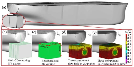
Figure 1. Reconstruction procedure of 3D-3C flow with multiple 2D-3C SPIV velocity planes
[18]: (
a) area of interest at the model aft; (
b) locations of multiple-2D scanning SPIV planes; (
c) reconstructed 3D volume; (
d) three-component flow field in 2D planes; (
e) three-component flow field in 3D volume.
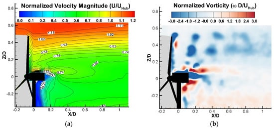
Figure 2. Stereoscopic PIV measurements of a wind turbine wake
[19]: (
a) Normalized velocity magnitude (TKE); (
b) Normalized vorticity.
Fluid flow around the FOWT substructure is three-dimensional and unsteady; it is a turbulent flow with a transient and rotational nature, such that a separation region could also form around the elements of the body in this nonuniform flow. It is incompressible, and viscous effects can be dominant depending on the incident wave and the shape of the platform.The geometric features of four floater types for FOWT applications are presented. The hydrodynamics of the SPAR platform, which are due to its simple, circular shape, could act as an inertia- or viscous-dominant body in different incident wave conditions. If the Keulegan–Carpenter (KC) number for the platform is less than 3, the platform has an inertia-dominant nature due to incoming waves, while for
3<KC<15, it can be assumed that the floater drag, in wave force loading terms, has a linear nature. Moreover, for
15<KC<45, the shape of the drag force follows a nonlinear trend, such that low-fidelity models such as the Morison equation cannot accurately anticipate the applying wave force
[20]. The hydrodynamics of barge-type floaters are easier to study because of their simple shape. However, there is some inconsistency when studying the effect of moonpool size on the platform hydrodynamics in wave conditions with a period near the resonance period of the floater
[21]. Concerning other platform types, i.e., semisubmersibles and TLPs, there can be complicated interactions between different elements of the body, such as the bracelet and main columns and the fluid flow. Low-fidelity models are unable to provide a compressive dynamic fluid body interaction (DFBI) analysis to provide a clear picture of this fluid flow interaction or of the wake area. High-fidelity models such as CFD can provide this full picture, and the validation data produced by PIV can significantly improve these numerical models as well as providing a benchmark that could aid researchers when selecting the mesh quality, a suitable equation for the wall condition based on the platform condition (e.g., to model marine growth on the floater), a turbulence model, and an appropriate value for tuning the turbulence model equations based on the flow regime and wave conditions. Since both CFD and SPIV can provide visualisation and numerical results that can be compared with each other, SPIV could act as a validation reference for CFD measurements.
Comprehensive reviews on particle image velocimetry measurements have been widely published in the literature. For example, the review conducted by Abdulwahab et al.
[22] provided a compressive investigation on the evolution of particle image velocimetry, its operational principals, and uncertainty and errors. In another review study conducted by Westerweel et al.
[23], the state of the art and the applicability of the method for measuring complex and turbulent flows were reviewed, and the past development in PIV measurement in order to reduce the method uncertainty was discussed. A summary of different implementations of the PIV method, such as PIV itself, SPIV, and tomographic PIV, along with their limitations and challenges in the field, was provided by Kähler et al.
[24].
Researchers aimed to provide its readers with the state of the art of underwater SPIV measurements in tank testing and identify opportunities for using the method in FOWT tank test campaigns to better understand the flows around the floater and provide a rich source of validation data for advanced numerical models. Despite the high-resolution results of SPIV, there are uncertainties associated with the laser frequency, tracer particle response, and hardware synchronisation in addition to limitations on the studied platform scale, data sampling rate, and SPIV instrumental setup for FOWT hydrodynamical measurements. Therefore, key considerations for SPIV use in FOWT tank tests are discussed.
The state of the art of PIV in tank tests is reviewed. Ship hydrodynamics, waves, and flow around simple primary geometric shapes such as cylinders in wave tanks are discussed. Because of different setup requirements for FOWT tank testing, there are challenges to making measurements in practice.
 +1 credit