Your browser does not fully support modern features. Please upgrade for a smoother experience.
Submitted Successfully!
 +1 credit
Thank you for your contribution! You can also upload a video entry or images related to this topic.
For video creation, please contact our Academic Video Service.
| Version | Summary | Created by | Modification | Content Size | Created at | Operation |
|---|---|---|---|---|---|---|
| 1 | Feng Jiang | -- | 2292 | 2023-06-20 09:30:31 | | | |
| 2 | Catherine Yang | + 1 word(s) | 2293 | 2023-06-20 09:38:56 | | |
Video Upload Options
We provide professional Academic Video Service to translate complex research into visually appealing presentations. Would you like to try it?
Cite
If you have any further questions, please contact Encyclopedia Editorial Office.
Dong, Z.; Jiang, F.; Tan, Y.; Wang, F.; Ma, R.; Liu, J. Wear Mechanism for Construction Machinery. Encyclopedia. Available online: https://encyclopedia.pub/entry/45837 (accessed on 22 July 2026).
Dong Z, Jiang F, Tan Y, Wang F, Ma R, Liu J. Wear Mechanism for Construction Machinery. Encyclopedia. Available at: https://encyclopedia.pub/entry/45837. Accessed July 22, 2026.
Dong, Zhengxing, Feng Jiang, Yuanqiang Tan, Fuzeng Wang, Rong Ma, Jiawen Liu. "Wear Mechanism for Construction Machinery" Encyclopedia, https://encyclopedia.pub/entry/45837 (accessed July 22, 2026).
Dong, Z., Jiang, F., Tan, Y., Wang, F., Ma, R., & Liu, J. (2023, June 20). Wear Mechanism for Construction Machinery. In Encyclopedia. https://encyclopedia.pub/entry/45837
Dong, Zhengxing, et al. "Wear Mechanism for Construction Machinery." Encyclopedia. Web. 20 June, 2023.
Copy Citation
Construction machinery, which is widely used in infrastructure construction, is growing rapidly all over the word. However, the complex working conditions of construction machinery lead to serious wear, particularly the wear of the bucket teeth on construction machinery. To control the wear procedure, it is essential to understand the wear mechanism and identify the wear form under variable working conditions.
bucket teeth
wear modeling
discrete element
1. Wear Mechanism of Bucket Teeth
There are numerous complex factors that affect the research on the wear of construction machinery’s wear parts. These factors interact with each other, further complicating the issue of wear on these parts. Therefore, in order to address the wear problems associated with construction machinery’s wear parts, it is crucial to first comprehend the wear mechanism and different forms of wear exhibited by various components. Jiang [1][2] et al. conducted extensive experimental studies to analyze the progression and manifestations of wear on loader pins. Their research revealed that the wear process of these pins can be primarily categorized into three stages: grinding, abrasive wear, and bonded wear. Each stage exhibits varying degrees of wear and distinct characteristics. Bucket teeth, being a vital component of construction machinery, are typically positioned at the forefront of excavator and loader buckets. These teeth come into direct contact with ores, gravel, and other materials, making them highly susceptible to significant and intricate wear. The wear of bucket teeth poses a complex challenge due to the diverse working environments and varying material contacts. Consequently, each part of the bucket teeth exhibits distinct forms of wear. After conducting an analysis, the researchers have established the wear mechanism of each part of the bucket teeth, as illustrated in Figure 1.
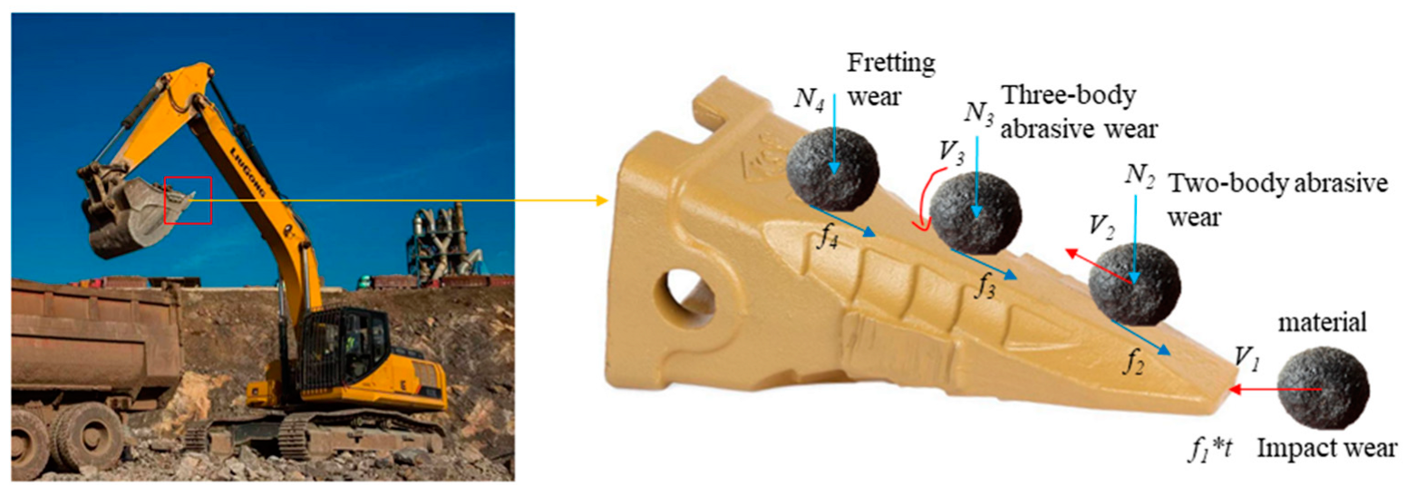
Figure 1. Tooth wear diagram of bucket.
The bucket teeth are a crucial component of the cantilever beam member in excavators. It comprises the shovel head, shovel seat, and ring clips, and its degree of wear and fracture directly affects the quality and efficiency of extraction. Bucket teeth come in different forms (Figure 2), including rock teeth, earth and rock square teeth, conical teeth, bucket teeth, and others [3]. The most common bucket tooth type is the conical tooth, located at the front of construction machinery, in direct contact with materials. This causes significant wear and varies in form. During excavation, the tip of the bucket teeth bear an impact load when inserted into materials, resulting in impact wear. As the bucket teeth deepen, the material above increases, causing relative sliding and two-body abrasive wear on the bucket teeth. As the bucket teeth deepen, materials roll along their surfaces into the bucket. The fine material’s gravity is negligible, and pressure on the bucket teeth is minimal, causing three-body abrasive wear [4]. The unloading of the excavator and loader bucket also experience three-body abrasive wear. Fretting wear has complex sources, including environmental vibrations and alternating stresses.
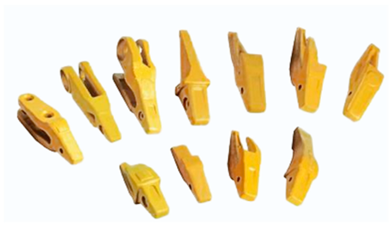
Figure 2. Different forms of bucket teeth.
2. Impact Wear
Impact wear [5] is a unique type of wear that is often observed in engineering, resulting from a combination of processes such as impact and sliding friction wear. This wear type occurs on the surface of the part that keeps the abrasive material crumbling. In impact wear, concentrated compressive stress is present at the abrasive contact, the plastic rheology, and fatigue of the ductile phase on the metal surface, while the hard phase is fractured. This indicates that the stress on the material has exceeded the crushing strength of the abrasive, making it high-stress wear [6]. When inserted and excavated into a mine, bucket teeth are subjected to strong impact loads, resulting in chiseled abrasive wear. The abrasive rock grains move rapidly on the metal surface of the bucket teeth, with their sharp edges resembling knives cutting the tooth surface. This action causes plastic deformation and forms plastic change grooves. The magnitude of the cutting resistance is determined by factors such as the nature and state of the ore rock, the geometry of the cutting part, the cutting angle, and the cutting thickness [7]. Figure 3 illustrates the working environment of construction machinery engaged in excavating materials under conditions of impact wear.
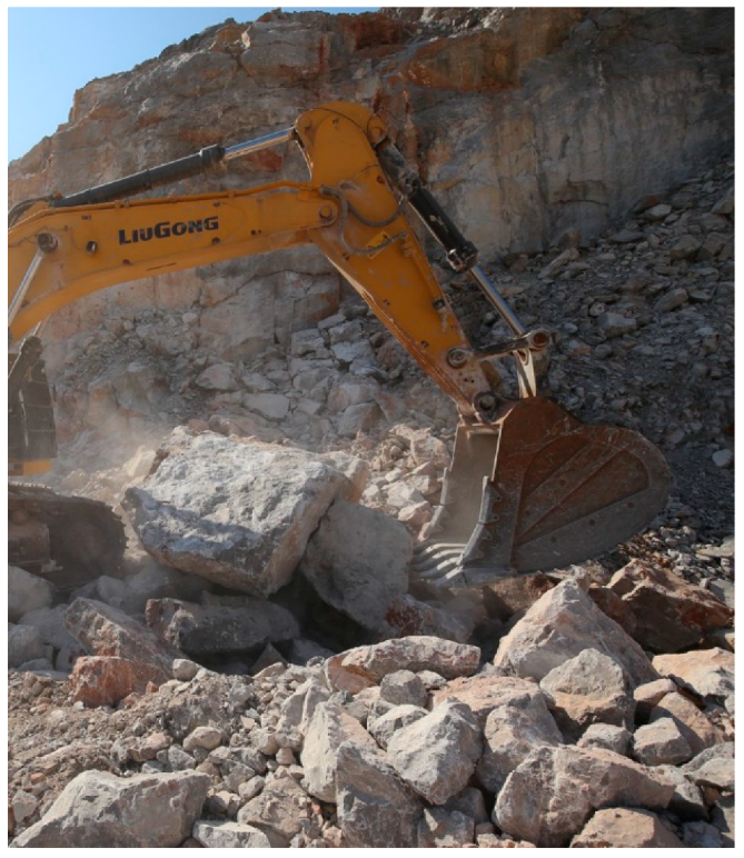
Figure 3. Working conditions with impact wear governed.
Rice et al. [8] investigated the pure impact wear behavior of different impact contact subs in a dry state interface environment with different impact contact forces and different impact frequency operating conditions, as well as the punch-cut composite impact wear behavior with different tangential velocities. Engel et al. [9] investigated the composite impact wear accompanied by sliding during impact and found that there is a zero wear period during the impact wear process. This is due to the time required for the sprouting, expansion, and fracture of fatigue cracks. Yang Yi [10] investigated the impact wear behavior of Fe-Mn-Al-C lightweight high manganese steel by selecting different test conditions and setting different rotational speeds on the specimens to compare and analyze the impact wear mechanism. Zhang et al. [11] studied the wear mechanism and wear mechanism of Mn13Cr2 high manganese steel by using an impact abrasive wear testing machine and other instrumentation to simulate an actual working environment; a large number of slip bands appeared in high manganese steel after impact, and the density of slip bands increased with the increase in impact work.
3. Abrasive Wear
Abrasive wear is the most prevalent type of wear in construction machinery and accounts for a significant portion of overall wear. Yan [12] et al. focused on the pin set of the ZL50 series loader and conducted extensive sample observations. Through analyzing the loader pin’s failure history, they determined that the primary form of wear on the pin is abrasive wear. Throughout the entire excavation process of construction machinery, abrasive wear persists for the longest duration.
There are several approaches to classify abrasive wear. Avery [13][14] classified it into chisel wear, high stress wear, and low stress or erosion wear, based on the stresses the wear parts undergo. Burwell [15] classified it into two-body abrasive wear and three-body abrasive wear, depending on the involvement of abrasive grains during wear. Two-body abrasive wear occurs when a hard surface scratches a softer surface during frictional motion, while three-body abrasive wear happens when an abrasive grain is caught between two surfaces and causes wear on one or both surfaces. Misra and Finniel [16] further refined the classification of abrasive wear in 1980. Gates [17] concluded that abrasive wear should be classified based on the amount of stress on the wear and the form of movement of the abrasive. The evolution of the classification of abrasive wear indicates its complexity.
Typically, the bucket scoops from the bottom upwards, and the bucket teeth slowly penetrate the material, resulting in relative sliding between the two. The weight of the material exerts pressure on the bucket teeth, causing sliding friction wear, which is a type of two-body abrasive wear. When discharging, the bucket is tilted downward, and the material rolls out of the bucket (Figure 4). At this point, there is minimal contact between the material and the bucket teeth, resulting in rolling friction wear, which is a type of three-body abrasive wear.
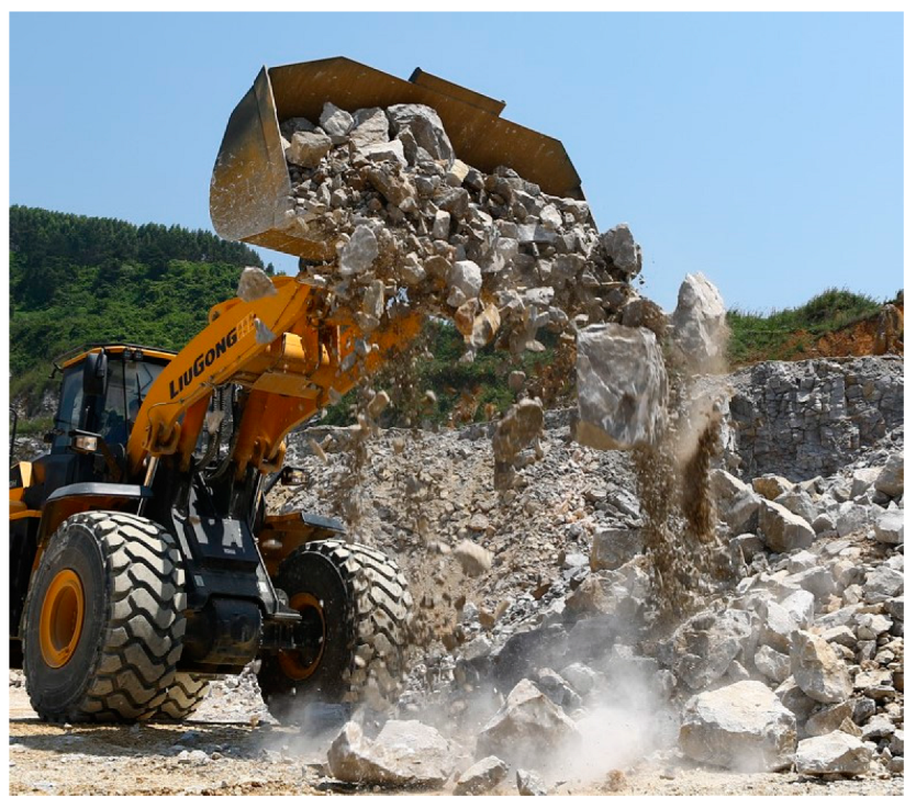
Figure 4. Working conditions with abrasive wear governed.
4. Fretting Wear
In the case of the two objects mentioned above, the contact surfaces experience mutual pressure and remain stationary. However, slight periodic vibrations or alternating stress in the environment cause small reciprocal sliding between the surfaces, leading to wear or motion vice during the non-running period. Unfortunately, people are often unaware of this type of wear due to the effects of environmental vibration and alternating stress, and it is therefore often overlooked. This type of wear is commonly referred to as fretting wear.
The phenomenon of fretting was first discovered by Eden in 1911, but did not attract attention until 1927, when Tomlinson [18] designed equipment to study the process of fretting and coined the term “fretting corrosion”. With more research, the phenomenon of fatigue fretting was discovered, and it was noted that it could accelerate fatigue damage. In their study on fretting wear mechanisms, Godfrey et al. [19] found that mechanical action is the primary factor causing wear on material surfaces, while oxidation is a secondary factor. When fixed bonding surfaces experience oxidation and adhesion, an abrasive chip (a third body) forms between the contact surfaces. From a different perspective, Godet et al. [20] put forth the fretting triplet theory based on earlier research. According to this theory, adhesion, plastic deformation, surface hardening, particle exfoliation, and the formation of abrasive chips on the contact surface occur due to continuous oxidation reactions. Zhang et al. [21] studied the impact of tangential force on micro-action fatigue and discovered that wear depth increases gradually with increasing tangential force. Moreover, higher tangential force reduces micro-action fatigue life and affects the expansion of fatigue cracks. Figure 5 displays several fundamental forms of micro-motion on the bucket teeth of construction machinery.
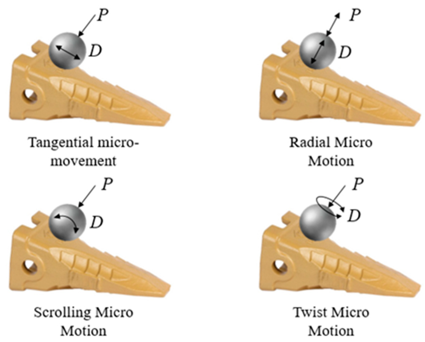
Figure 5. The basic form of micro-movement of the material on the bucket teeth [22].
Fretting wear causes plastic deformation and cracks in micro-convex bodies on friction subjoint surfaces due to contact pressure [23]. Additionally, the oxide or lubricating film on the contact surface is destroyed, leading to weld adhesion and knot formation between surfaces [24]. During fretting wear, chemical activity plays a significant role in the formation of oxide chips on the shear-off bonding points and exposed nascent surfaces. The interaction of oxygen with these surfaces leads to gradual oxidation. The generated oxide chips can cause abrasive wear and contact zone fatigue, especially due to the small amplitude, low relative velocity of sliding, and close fitting of the surface [25]. These oxide chips are not easily unloaded or dislodged from the contact area, so they act as abrasives during abrasive wear.
5. Wear Morphology
The surface locations of bucket teeth exhibit diverse forms of wear, leading to distinct wear profiles for each component of the bucket teeth. In the case of mining excavator bucket teeth, the majority of them exhibit high-stress wear across all surfaces. This wear is predominantly characterized by micro-cutting and plastic pear grooves, which are classified as abrasive wear and dominate the overall wear of the bucket teeth [26]. The formation of surface cracks caused by this wear leads to the accumulation of materials such as rocks on the teeth, which in turn causes Ca, O, K, Na, Si, and Al elements from sand and gravel to penetrate the bucket teeth. This process alters the original composition of the wear-resistant alloy, rendering it non-wear-resistant and resulting in a depletion or enrichment of surface alloy elements. This difference in composition between the surface and substrate of the tooling weakens its anti-wear performance, accelerates wear rate, and ultimately reduces tooling life [27].
Hu’s study [28] examined the macroscopic morphology of failed bucket teeth and found that when in contact with ore, deep wear grooves and impact craters were formed on the tooth surface. A thick deformation layer was also observed on the surface of the bucket teeth, with severe plastic deformation in areas where the metal was folded on the wear surface. The wear subsurface morphology showed the appearance of a white bright layer in the deeper subsurface of the wear groove, known as the adiabatic shear layer. Although hard and corrosion resistant, this thin, brittle layer is undesirable, as it is prone to cracking and accelerates machine damage. The occurrence of the adiabatic shear layer indicates poor shear resistance of the material, making it susceptible to plastic destabilization during abrasive particle cutting or deformation. The deformation of the metal generates heat, which raises the temperature and softens the material, promoting further deformation and warming. The heat cannot be transferred to the surrounding area, leading to rapid cooling and the formation of fine martensite organization in the subsequent layer. Observations of the abrasive chip morphology showed small cutting chips. The formation of adiabatic shear layers and the generation of heat during the deformation of the metal can have a significant impact on the wear resistance of bucket teeth. By conducting further research on the material properties and design of bucket teeth, it may be possible to reduce the occurrence of adiabatic shear layers and improve the wear resistance of bucket teeth, ultimately leading to improved efficiency and reduced costs for the construction industry. In conclusion, understanding the morphology of failed bucket teeth and the factors that contribute to their wear resistance is essential for improving the efficiency of construction machinery. Further research on the material properties and design of bucket teeth is necessary for reducing the occurrence of adiabatic shear layers and improving the overall wear resistance of bucket teeth.
Valtonen et al. [26] compared the wear of a mining loader bucket’s cutting edge with laboratory samples using various wear testing methods to simulate laboratory conditions. They characterized the wear surfaces and cross sections of the bucket’s cutting edges and test specimens and found that work hardening occurred in all tested bucket wear steels, but the amount of plastic deformation and depth of wear varied. Valtonen et al. [29] investigated the hardness of wear-resistant steel and the impact of different abrasives on its wear rate and wear mechanism under laboratory conditions. They discovered that as the hardness of wear-resistant steel increased, the deformation of the wear surface decreased and the scratches produced by abrasive wear were most noticeable in the softer wear-resistant steel. They also found that the effect of abrasive type on the wear mechanism of wear-resistant steel was more significant than the impact of the hardness of wear-resistant steel. Thus, their study suggests that the type of abrasive is a critical factor to consider when examining the wear mechanism of wear-resistant steel. According to Keles et al. [30], bucket teeth develop a slat-martensite synthetic organization after heat treatment. Martensitic microstructure can have various forms such as slat, spiral, lenticular, and thin plates [31]. Among these morphologies, slat morphology is typically observed, as it can be easily formed through a simple heat treatment process.
References
- Jiang, F.; Lim, F.; Li, J. Abrasion Course Analysis on Pins of Loader Working Equipment and lmproverment. Lubr. Eng. 2007, 191, 132–135. (In Chinese)
- Zhang, T.; Wang, N.; Cheng, X. The comparison research on design methodology of pins. J. Mech. Strength 2015, 37, 461–466. (In Chinese)
- Cristine, H.; Tasevski, A. Design of Bucket Teeth. Master’s Thesis, Mälardalens University, Västerås, Sweden, 2016.
- Williams, J.A. Wear and wear particles—some fundamentals. Tribol. Int. 2005, 38, 863–870.
- Chen, X.-D.; Wang, L.-W.; Yang, L.-Y.; Tang, R.; Yu, Y.-Q.; Cai, Z.-B. Investigation on the impact wear behavior of 2.25 Cr–1Mo steel at elevated temperature. Wear 2021, 476, 203740.
- Dhirendra, K.S.; Vijay, K.J. Analysis of surface texture generated by a flexible magnetic abrasive brush. Wear 2005, 259, 1254–1261.
- Zhang, W. Study on the failure Mechanism and Control of Bucket Teeth in Large-scale Mine Excavator. Nonferrous Metall. Equip. 2017, 3, 5–10+31. (In Chinese)
- Rice, S.L.; Nowotny, H.; Wayne, S.F. Characteristics of metallic subsurface zones in sliding and impact wear. Wear 1981, 74, 131–142.
- Engel, P.A.; Lyons, T.H.; Sirico, J.L. Impact wear model for steel specimens. Wear 1973, 23, 185–201.
- Yang, Y. Research on the Microstructure, Mechanical and Impact Abrasion Behavior of Fe-Mn-Al-C Lightweight High Manganese Steel. Master’s Thesis, Nanchang Hangkong University, Nanchang, China, 2021. (In Chinese).
- Zhang, F.; Shao, F.; Zhou, D. Research on Impact Wear Mechanism of High Manganese Steel Mn13Cr2. J. Hunan Univ. (Nat. Sci.) 2014, 41, 6–10. (In Chinese)
- Yan, L.; Jiang, F.; Rong, Y. Application of Equal Life Methodology on Design of Pin Group. J. Mech. Eng. 2013, 49, 130–136. (In Chinese)
- Rhoades, L. Abrasive flow machining: A case study. J. Mater. Process. Technol. 1991, 28, 107–116.
- Davies, P.J.; Fletcher, A.J. The assessment of the rheological characteristics of various polyborosiloxane/grit mixtures as utilized in the abrasive flow machining process. Proc. Inst. Mech. Eng. Part C J. Mech. Eng. Sci. 1995, 209, 409–418.
- Wang, A.C.; Weng, S.H. Developing the polymer abrasive gels in AFM processs. J. Mater. Process. Technol. 2007, 192, 486–490.
- Sankar, M.R.; Jain, V.; Ramkumar, J.; Joshi, Y. Rheological characterization of styrene-butadiene based medium and its finishing performance using rotational abrasive flow finishing process. Int. J. Mach. Tools Manuf. 2011, 51, 947–957.
- Singla, S.; Kang, A.S.; Grewal, J.S.; Cheema, G.S. Wear behavior of weld overlays on excavator bucket teeth. Procedia Mater. Sci. 2014, 5, 256–266.
- Tomlinson, G.A.; Thorpe, P.L.; Gough, H.J. An investigation of the fretting corrosion of closely fitting surfaces. Proc. Inst. Mech. Eng. 1939, 141, 223–249.
- Godfrey, D. Investigation of Fretting by Microscopic Observation; Lewis Flight Propulsion Laboratory: Cleveland, Ohio, 1951.
- Godet, M. Third-bodies in tribology. Wear 1990, 136, 29–45.
- Zhang, H.; Liu, J.; Zuo, Z. Investigation into the effects of tangential force on fretting fatigue based on XFEM. Tribol. Int. 2016, 99, 23–28.
- Li, L. Development and Experimental Study of a Testing Machine for Fretting Friction Wear. Master’s Thesis, Nanjing University of Aeronautics and Astronautics, Nanjing, China, 2010. (In Chinese).
- Straffelini, G.; Molinari, A. Mild sliding wear of Fe–0.2% C, Ti–6% Al–4% V and Al-7072: A comparative study. Tribol. Lett. 2011, 41, 227–238.
- Straffelini, G.; Molinari, A. Dry sliding wear of Ti–6Al–4V alloy as influenced by the counterface and sliding conditions. Wear 1999, 236, 328–338.
- Kong, H.; Ashby, M.F. Wear mechanisms in brittle solids. Acta Metall. Et Mater. 1992, 40, 2907–2920.
- Valtonen, K.; Keltamäki, K.; Kuokkala, V.T. High-stress abrasion of wear resistant steels in the cutting edges of loader buckets. Tribol. Int. 2018, 119, 707–720.
- Yang, L.J. A methodology for the prediction of standard steady-state wear coefficient in an aluminium-based matrix composite reinforced with alumina particles. J. Mater. Process. Technol. 2005, 162, 139–148.
- Hu, Y. Analysis on Wear Failure of Bucket Teeth of Mine Excavators and the Anti-wear Measures. Lubr. Eng. 2006, 5, 165–167. (In Chinese)
- Valtonen, K.; Ratia, V.; Ojala, N.; Kuokkala, V.-T. Comparison of laboratory wear test results with the in-service performance of cutting edges of loader buckets. Wear 2017, 388, 93–100.
- Keleş, A.; Yildirim, M. Improvement of mechanical properties by means of titanium alloying to steel teeth used in the excavator. Eng. Sci. Technol. Int. J. 2020, 23, 1208–1213.
- Morito, S.; Tanaka, H.; Konishi, R.; Furuhara, T.; Maki, T. The morphology and crystallography of lath martensite in Fe-C alloys. Acta Mater. 2003, 51, 1789–1799.
More
Information
Subjects:
Engineering, Mechanical
Contributors
MDPI registered users' name will be linked to their SciProfiles pages. To register with us, please refer to https://encyclopedia.pub/register
:
View Times:
1.3K
Revisions:
2 times
(View History)
Update Date:
20 Jun 2023
Table of Contents


Notice
You are not a member of the advisory board for this topic. If you want to update advisory board member profile, please contact office@encyclopedia.pub.
OK
Confirm
Only members of the Encyclopedia advisory board for this topic are allowed to note entries. Would you like to become an advisory board member of the Encyclopedia?
Yes
No
${ textCharacter }/${ maxCharacter }
Submit
Cancel
Back
Comments
${ item }
|
${ item.createdUser.fullName }
${ item.createdAt }
${ item.vote }
${ item.reply }
Delete
${ reply.createdUser.fullName }
${ reply.createdAt }
${ reply.vote }
Delete
There is no reply to this comment~
${ item.replyTextCharacter }/${ item.replyMaxCharacter }
Submit
Cancel
More
No more~
There is no comment~
${ textCharacter }/${ maxCharacter }
Submit
Cancel
${ selectedItem.replyTextCharacter }/${ selectedItem.replyMaxCharacter }
Submit
Cancel
Confirm
Are you sure to Delete?
Yes
No