Your browser does not fully support modern features. Please upgrade for a smoother experience.
Submitted Successfully!
 +1 credit
Thank you for your contribution! You can also upload a video entry or images related to this topic.
For video creation, please contact our Academic Video Service.
| Version | Summary | Created by | Modification | Content Size | Created at | Operation |
|---|---|---|---|---|---|---|
| 1 | Fahad Zafar | -- | 2665 | 2023-05-10 14:29:30 | | | |
| 2 | Lindsay Dong | + 2 word(s) | 2667 | 2023-05-11 03:07:18 | | |
Video Upload Options
We provide professional Academic Video Service to translate complex research into visually appealing presentations. Would you like to try it?
Cite
If you have any further questions, please contact Encyclopedia Editorial Office.
Zafar, F.; Emadinia, O.; Conceição, J.; Vieira, M.; Reis, A. Direct Laser Deposition of Inconel 625. Encyclopedia. Available online: https://encyclopedia.pub/entry/44108 (accessed on 24 June 2026).
Zafar F, Emadinia O, Conceição J, Vieira M, Reis A. Direct Laser Deposition of Inconel 625. Encyclopedia. Available at: https://encyclopedia.pub/entry/44108. Accessed June 24, 2026.
Zafar, Fahad, Omid Emadinia, João Conceição, Manuel Vieira, Ana Reis. "Direct Laser Deposition of Inconel 625" Encyclopedia, https://encyclopedia.pub/entry/44108 (accessed June 24, 2026).
Zafar, F., Emadinia, O., Conceição, J., Vieira, M., & Reis, A. (2023, May 10). Direct Laser Deposition of Inconel 625. In Encyclopedia. https://encyclopedia.pub/entry/44108
Zafar, Fahad, et al. "Direct Laser Deposition of Inconel 625." Encyclopedia. Web. 10 May, 2023.
Copy Citation
The direct laser deposition (DLD) process has seen rigorous research in the past two decades due to its ability to directly manufacture products followed by minimal machining. The process input variables play a vital role in determining the properties achieved in the products manufactured by the DLD method. Inconel 625, a nickel-based superalloy with exceptional mechanical performance and corrosion resistance, has been used in critical applications within the aerospace, process, and marine industry.
additive manufacturing
direct laser deposition
Inconel 625
laser directed energy deposition
microstructure
high temperature properties
1. Introduction
Nickel-based superalloys are the preferred choice for applications involving fatigue and/or creep resistance and the ability to withstand corrosive attacks from the operating environment. These alloys have gained increasing popularity in the marine, aerospace, energy, and automobile sectors in the past few decades due to their unique properties. However, nickel superalloys have poor machinability causing excessive tool wear, shorter tool life, large power consumption, and low productivity during machining [1][2][3]. Additionally, these alloys have the propensity to accumulate residual stresses and various defects, which can promote catastrophic component failure during their service life [4].
AM of metals, with its exceptional freedom of creating complex geometries using layer by layer fabrication approach combined with tailored material properties, has unveiled a new horizon of manufacturing. With more recent developments each year, AM has evolved from a rapid prototyping technology into a preferred fabrication method in several industries for a substantial number of products. Regarding the non-sintering methodologies presented in ISO-ASTM 52900, AM processes involve power sources such as electron or laser beams, arc, and plasma [5] (pp. 3–10). Based on the type of raw materials consumed, these AM processes can be classified into powder bed, direct powder feed (via coaxial nozzle), or wire feeding process.
Laser-directed energy or direct laser deposition (DLD) can be used for single or multi-material deposition for repair, cladding, or producing large-volume parts. DLD is defined as a “process in which focused thermal energy of the laser melts the material being deposited”. DLD processes can use multi-kW lasers with spot sizes of several millimeters to deposit as much material per unit of time as possible. Being an in-situ powder feeding process, it allows fabricating parts without any enclosed chamber. DLD can also produce components with different compositions, layer by layer, through the mixing of different powders, known as functionally graded materials, which is challenging to realize in laser powder bed fusion (LPBF). As an example, DLD systems, such as those offered by RPM Innovations®, can deposit over a meter-long complex shape. Scaling to even larger sizes is possible, as robots can be attached to large gantry systems and moved over large distances [6]. DLD also offers the possibility of freedom from cost-intensive post-processing operations, e.g., hot isostatic processing (HIP), heat treatment, surface finishing, etc., which are usually complementary to AM components built by LPBF techniques. However, such additional post-processing steps tend to undermine the business case for using AM production [6].
2. Wrought vs. Additive Manufactured IN625
IN625 was initially developed as a solid solution-strengthened alloy for high-temperature applications, although the alloy can also gain some further strength by carbide and/or intermetallic compound precipitation [7]. It has good weldability and fabricability, making it suitable for diverse engineering applications, particularly involving high-temperature creep and/or fatigue conditions.
High melting solute elements (molybdenum, niobium) have a low diffusivity in nickel matrix [8]; thus, their presence in solid solution enhances the creep strength of the alloy [9], while chromium, although having a small hardening coefficient, still contributes appreciably to solid solution-strengthening due to its high weight fraction in IN625 [10]. Carbon also serves as a potent solid solution strengthening element as well as a source for primary and secondary carbide strengthening [11]. IN625 has a face-centered cubic (FCC) crystal structure similar to other nickel-based superalloys, which resist phase transformations from room temperature up to the melting point. In addition, the FCC structure has lower rates of thermally activated processes influencing the creep deformation phenomena. The resistance to external surface degradation by oxidation and hot corrosion is controlled primarily by chromium, aluminum, and titanium [10].
Mechanical Properties
Wrought IN625 has moderately high mechanical properties at room temperature. However, its elevated temperature mechanical properties distinguish it from steels having equivalent strengths. ASTM B443 specifies the minimum requirements for sheet/plate, and the ASTM B564 standard specifies the requirements for IN625 forging. ASTM E8 and ISO 6892 are the standard methods for room temperature uniaxial tension testing of metallic materials, while ASTM E21 and ISO 6892 provide methods for tension testing of metals at elevated temperatures (above 38 °C), applicable to both wrought and AM IN625. ASTM E292 and ASTM E740 standard test methods determine the rupture strength (elevated temperature) and residual strength in the notched specimen under tensile loading. The test methods mentioned above apply to both conventionally and additively manufactured IN625 material.
DLD IN625 meets/surpasses the ultimate tensile strength (UTS), yield strength (YS), and elongation (%) specification for conventionally manufactured IN625 products. However, the AM IN625 generally presents lower ductility when compared with conventionally manufactured IN625, having typical elongation values lying between ~60 and 65%. DLD builds have higher UTS, YS, lower %elongation in the XY direction, and lower UTS, YS, and higher elongation in the Z-direction. Isotropic behavior is evident in the mechanical properties of DLD builds. Most DLD builds present a UTS and YS within 820–880 MPa and 460–600 MPa, respectively, in the XY (horizontal)-direction and 730–840 MPa and 370–510 MPa in Z (build)-direction, respectively.
Two different studies have been conducted to compare the mechanical properties of builds produced by selective laser melting (SLM) and DLD [12][13]. J. Nguejio et al. [13] concluded that with adequate parameters and post-heat treatment, DLD provided better strength with more than 40% elongation compared to SLM build. Whereas F. Chen et al. [12] reported relatively lower (~30%) elongation and a lower strength with considerable variation in elongation in XY and Z directions for DLD builds as compared to SLM builds after heat treatment with minimal anisotropic behavior. Thus, the selection of the process has its own merits for a certain product and desired mechanical properties for the intended application.
3. Microstructure and Phase Evolution in Direct Laser Deposited IN625
Several researchers have studied the microstructure evolution and phase transformation in DLD IN625. However, a lack of sufficient information about the location/orientation of the sample or adopting non-standard practices in others may render the data less beneficial to the reader. An effort has been made here to present micrographs with sample orientation information symbols on each (wherever sufficient information is available from the original work). ASTM 52921 [14] terminology guidelines have been adopted for presenting the orientation of samples. IN625 has been successfully deposited using DLD by several researchers without relevant defects, such as cracks, high porosity, or bonding errors, at the interface between the substrate and deposit.
Since the cooling direction changes with the scan direction, the resultant heat flux direction rotates to be very close to the direction of secondary dendrites of the preceding layer. These secondary dendrites act as a growth site for the primary dendrites of newly solidifying layers, which results in an angle of 90° among the primary dendrites in subsequent layers.
Although it has been indicated in the literature [15][16] that the grains preferentially orient to <001> due to the vertical heat flux direction, resulting in the growth of primary dendrites at an angle of about 90° with the substrate, J. Nguejio et al. [13] reported that primary dendrites are not oriented at a right angle to the substrate, and instead appear as inverted V’s in deposited layers.
3.1. Laves Phase and Carbides
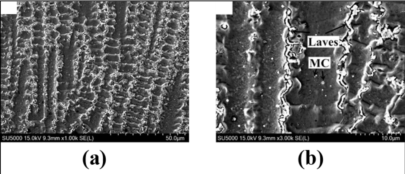
Figure 1a,b present the vertical cross-section (parallel to the building direction) of the DLD-IN625 in the as-built condition. Very fine precipitates with a brighter contrast can be observed as a continuous chain-like distribution and small block-like precipitates within the inter-dendritic region. These precipitates are identified as Laves phases and MC carbides [17] using localized chemical analysis. However, the formation of these phases can be confirmed by applying transmission electron microscope (TEM) analysis [18]. According to the Ni–Nb–C equilibrium phase diagram, with sufficiently high concentrations of Nb and C in the molten pool, MC carbides are precipitated by eutectic reactions (L --> γ + MC), which are characterized by spherical/blocky morphology and cubic crystal structure, as observed by TEM and the corresponding selected area electron diffraction (SAED) pattern in these images. When the as-built DLD-IN625 is heat treated at 1000 and 1100 °C, the recrystallization tends to proceed with increasing temperature and some of the Laves phase particles dissolve into the solution to precipitate as MC carbides. The rest of the Laves phase particles tend to transform into rod-like shapes [18].
Figure 1. As-deposited and annealed samples at different temperatures; the vertical cross-section (Plane B, X-Z): (a,b) without heat treatment.
4. Creep Strength of DLD IN625
The ability of a solid material to undergo irreversible deformation because of persistent mechanical stresses is known as creep. Long-term exposure to such stresses, which are still below the material’s yield strength, leads to creep deformation. In materials exposed to higher temperatures, creep is more severe and typically worsens as the temperature rises closer to the melting point (Tm).
Materials deform plastically at low temperatures and high stresses rather than creep. Diffusional creep typically prevails at high temperatures and moderate stress, whereas dislocation creep typically predominates at high temperatures and high stress. Since wrought IN625 has been the engineers’ choice for mid–high temperatures (usually between 0.6 and 0.8 Tm for nickel superalloys) and moderate stress applications [19], it becomes equally important to study the creep strength and creep deformation mechanism in DLD IN625 to assess its suitability for such demanding applications.
In the range of high-temperature creep (0.6 Tm), strengthening is diffusion-controlled and slow-diffusing, large atoms (elements), such as molybdenum, Niobium, and tungsten, tend to be the most effective solid-solution hardeners. Primary carbides can enhance strength by intragranular dispersion hardening. On the other hand, secondary carbides can significantly influence the creep strength, subject to the morphology of carbides, wherein discrete (discontinuous) grain boundary carbides are desired for creep resistance [11]. The presence of Nb in the IN625 alloy leads to a precipitation-hardening with the formation of Ni3Nb (γ″ or δ) phases above 537 °C [20]. The stable δ phase (orthorhombic) typically appears at grain boundaries above 760 °C [20][21]. Aside from the Ni3Nb type phases, MC, M6C, and M23C6 carbides (M for metallic element and C for carbon) typically form over the temperature range from 600 °C to 1200 °C [21][22].
Upon atomic probe tomographic analysis, the oxygen concentration at the grain boundary of creep-deformed AM IN625 was found to be too low to result in embrittlement. Nano-secondary ion mass spectrometric analysis revealed substantial sulfur segregation of Al2O3 in both as-HIPed and long-cycle heat-treated AM alloys. Al2O3 inclusions at secondary cracks in the creep-tested AM IN625 alloys led to the finding that sulfur embrittlement is the most likely cause of embrittlement in LPBF IN625 [23].
5. Fatigue Strength and Fracture Toughness of DLD IN625
According to ASTM’s standard terminology, “Fatigue is the progressive localized permanent structural change occurring in a material subjected to conditions that produce fluctuating stresses and strains at some point or points, and that may culminate in cracks or complete fracture after a sufficient number of fluctuations”.
Therefore, fatigue strength should be duly considered during the design phase when creating components that will be subjected to continuous cyclic stress. The components made of Inconel alloys are typically subjected to cyclic loading, which may eventually lead to fatigue failure. In general, fatigue tests are carried out in accordance with ASTM E606 (strain-controlled), ASTM E466 (force-controlled), or other comparable standards depending upon the intended application. The degree of porosity and the final microstructure of the manufactured parts, which in turn depend on the deposition cooling rate, have a considerable impact on the outcomes of the fatigue test.
Thermal–Mechanical Fatigue Resistance of DLD IN625
Thermal–mechanical fatigue (TMF) is a specific type of fatigue that occurs when materials are subjected to simultaneous cyclic loads combined with high cyclic temperatures. In demanding engineering applications, e.g., jet engine turbine blades working at high-temperature ranges and varying mechanical loads, the role of TMF becomes increasingly important. During TMF, three main damage mechanisms—fatigue, oxidation, and creep—are frequently encountered. These mechanisms may act alone or in combination with test circumstances, such as maximum and minimum temperatures, temperature amplitude, total strain amplitude, test frequency, the phase angle between temperature, and strain, dwell duration, or environmental factors. No such study has been reported for AM IN625, which typically lies within the defined scope of ASTM E2368 (standard for thermomechanical fatigue testing) materials.
6. Effect of Laser/Powder Interaction
The laser energy interacts with the powder jet before it reaches the substrate, with some energy being absorbed by the powder particles and the other being reflected [24]. In the DED process, a fraction of the total heat energy is consumed in heating the powder particles after emerging from the nozzle and traveling through the beam. The energy absorbed by in-flight powder particles depends on the gas flow rate, the powders’ material properties, laser power density, and laser/powder interaction time or residence time [24]. A small molten pool is produced due to the residual beam energy impinging on the deposit surface. The amount of energy absorbed by the substrate is further influenced by the shielding gas, deposit geometry, and beam properties.
7. Fabrication of Inconel 625-Based Advanced Materials Using Laser-Directed Energy Deposition
7.1. IN625-Based Composites
MMCs consist of strong second-phase particles/fibers, etc., dispersed within a metallic matrix, with the primary intention being to enhance stiffness, creep, or wear resistance, etc., while maintaining toughness which presents a challenge. Several ceramic and carbon-based (graphene, carbon nanotubes) reinforcements have gained the attention of researchers and have been used for IN625 MMCs. Here, the scholars are interested in discussing the ceramic reinforcements (oxides, carbides, borides, etc.) utilized and the factors influencing the modifying properties of IN625. A sound DLD composite should demonstrate a dense, mechanically and thermally stable structure with good wear resistance and electrochemical suitability to operate in its intended environments, which broadly depends on the feedstock and processing conditions.
7.2. Effect of Mixing
The mixing technique adopted prior to the processing of MMCs substantially affects the quality of the deposit and the overall build’s properties. K. Bazaleeva et al. compared the IN625/TiC built by simultaneously feeding IN625-TiC powders through different nozzles, IN625-TiC powders mixed by a gravitational mixer, and the IN625-TiC powder mixed by ball milling. IN625-TiC powders mixed by a gravitational mixer presented two distinct zones upon DLD, labelled I (small carbide distributed uniformly) and II (dendritic carbides distributed in matrix).
7.3. Effect of Reinforcement on Microstructure
Different reinforcements, such as carbides, borides, and oxides, have been attempted as a reinforcement to IN625 in DLD processing. TiC has most frequently been utilized with IN625 for the DLD of IN625/TiC composites, which tends to provide the necessary undercooling for secondary dendrite growth. The degree of undercooling (difference between the equilibrium liquidus temperature and the dendrite tip temperature) is the driving force for dendritic growth [6].
8. Oxidation Resistance of DLD IN625 Composites
Chen Hong et al. studied the effect of different weight percentages (2.5 and 5 wt.%) of TiC reinforcement in IN625 on the oxidation resistance of the resulting composites produced by DLD. They conducted oxidation resistance tests at 600, 800, and 1000 °C for 100 h in air. The composite of 5 wt.% of TiC showed the best oxidation resistance with the least mass gain (0.3233 mg·cm−2). The IN625–5 wt.% TiC showed excellent oxidation resistance up to 800 °C.
9. Corrosion Resistance of DLD IN625 Composites
The outstanding corrosion resistance of IN625 has attracted the attention of researchers because it imparts corrosion resistance to relatively less expensive structural materials using the DLD technique. IN625-WC composite coatings were deposited on a 2Cr13 steel substrate using DLD by Zhi-Hua Tian et al. using 10–20 wt.% of WC reinforcement to impart wear and corrosion resistance, respectively, simultaneously. The best corrosion resistance and substantial increase in hardness (compared to the substrate) were observed using a 10 wt.% WC/IN625 powder mixture for DLD on 2Cr13 steel. The microstructure was mainly composed of γ-(Ni, Fe), M23C6, and NbC.
References
- Davis, J.R. 6.4.1 General Oxidation. In ASM Specialty Handbook—Nickel, Cobalt, and Their Alloys; ASM International: Materials Park, OH, USA, 2000; p. 86.
- Kutz, M. Mechanical Engineers’ Handbook—Materials and Engineering Mechanics, 4th ed.; John Wiley & Sons: Hoboken, NJ, USA, 2015.
- Zhu, D.; Zhang, X.; Ding, H. Tool wear characteristics in machining of nickel-based superalloys. Int. J. Mach. Tools Manuf. 2013, 64, 60–77.
- Thakur, A.; Gangopadhyay, S. State-of-the-art in surface integrity in machining of nickel-based super alloys. Int. J. Mach. Tools Manuf. 2016, 100, 25–54.
- Bourell, D.L.; Frazier, W.; Kuhn, H.; Seifi, M. 1. Introduction to Additive Manufacturing. In ASM Handbook®, Volume 24—Additive Manufacturing Processes; ASM International: Materials Park, OH, USA, 2020; pp. 3–10.
- DebRoy, T.; Wei, H.L.; Zuback, J.S.; Mukherjee, T.; Elmer, J.W.; Milewski, J.O.; Beese, A.M.; Wilson-Heid, A.; De, A.; Zhang, W. Additive manufacturing of metallic components—Process, structure and properties. Prog. Mater. Sci. 2018, 92, 112–224.
- Sundararaman, M.; Mukhopadhyay, P.; Banerjee, S. Precipitation of the δ-Ni3Nb phase in two nickel base superalloys. Metall. Trans. A 1988, 19, 453–465.
- Smithells, C.J. Metals Reference Book, 7th ed.; Butterworths: London, UK, 1976.
- Pelloux, R.; Grant, N. Solid Solutions And Second Phase Strengthening of Nickel Alloys at High And Low Temperatures; Massachusetts Instutute of Technology, Deptarmetn of Metallurgy: Cambridge, MA, USA, 1959.
- Jena, A.K.; Chaturvedi, M.C. The role of alloying elements in the design of nickel-base superalloys. J. Mater. Sci. 1984, 19, 3121–3139.
- Totten, G.E. 23.1 Wrought Nickel Alloys. In ASM Handbook Volume 4E—Heat Treating of Nonferrous Alloys; ASM International: Materials Park, OH, USA, 2016; p. 427.
- Chen, F.; Wang, Q.; Zhang, C.; Huang, Z.; Jia, M.; Shen, Q. Microstructures and mechanical behaviors of additive manufactured Inconel 625 alloys via selective laser melting and laser engineered net shaping. J. Alloys Compd. 2022, 917, 165572.
- Nguejio, J.; Szmytka, F.; Hallais, S.; Tanguy, A.; Nardone, S.; Godino Martinez, M. Comparison of microstructure features and mechanical properties for additive manufactured and wrought nickel alloys 625. Mater. Sci. Eng. A 2019, 764, 138214.
- Guidelines for Determining Coordinate Systems and Testing Methodologies in AM Processes; ASTM: West Conshohocken, PA, USA, 2019; p. 14.
- Dinda, G.P.; Dasgupta, A.K.; Mazumder, J. Laser aided direct metal deposition of Inconel 625 superalloy: Microstructural evolution and thermal stability. Mater. Sci. Eng. A 2009, 509, 98–104.
- Li, S.; Wei, Q.; Shi, Y.; Zhu, Z.; Zhang, D. Microstructure Characteristics of Inconel 625 Superalloy Manufactured by Selective Laser Melting. J. Mater. Sci. Technol. 2015, 31, 946–952.
- Qin, L.; Chen, C.; Zhang, M.; Yan, K.; Cheng, G.; Jing, H.; Wang, X. The microstructure and mechanical properties of deposited-IN625 by laser additive manufacturing. Rapid Prototyp. J. 2017, 23, 1119–1129.
- Xingcheng, W.; Chen, C.; Qin, L.; Zhang, M. Microstructure Evolution and Mechanical Behavior of Inconel 625 Produced Using Direct Laser Metal Deposition. Phys. Met. Metallogr. 2021, 122, 896–907.
- Davis, J.R. 3.3 References. In ASM Specialty Handbook—Nickel, Cobalt, and Their Alloys; ASM International: Materials Park, OH, USA, 2000; p. 5.
- Floreen, S.; Fuchs, G.E.; Yang, W.J.S. The Metallurgy of Alloy 625. In Superalloys; Knolls Atomic Power Laboratory: Niskayuna, NY, USA, 1994; pp. 13–37.
- Reed, R.C. The Superalloys: Fundamentals and Applications; Cambridge University Press: Cambridge, UK, 2008.
- Sundararaman, M.; Mukhopadhyay, P.; Banerjee, S. Carbide precipitation in nickel base superalloys 718 and 625 and their effect on mechanical properties. Superalloys 1997, 718, 367–378.
- Son, K.-T.; Phan, T.Q.; Levine, L.E.; Kim, K.-S.; Lee, K.-A.; Ahlfors, M.; Kassner, M.E. The creep and fracture properties of additively manufactured inconel 625. Materialia 2021, 15, 101021.
- Manvatkar, V.; De, A.; DebRoy, T. Heat transfer and material flow during laser assisted multi-layer additive manufacturing. J. Appl. Phys. 2014, 116, 124905.
More
Information
Contributors
MDPI registered users' name will be linked to their SciProfiles pages. To register with us, please refer to https://encyclopedia.pub/register
:
View Times:
1.3K
Revisions:
2 times
(View History)
Update Date:
11 May 2023
Table of Contents


Notice
You are not a member of the advisory board for this topic. If you want to update advisory board member profile, please contact office@encyclopedia.pub.
OK
Confirm
Only members of the Encyclopedia advisory board for this topic are allowed to note entries. Would you like to become an advisory board member of the Encyclopedia?
Yes
No
${ textCharacter }/${ maxCharacter }
Submit
Cancel
Back
Comments
${ item }
|
${ item.createdUser.fullName }
${ item.createdAt }
${ item.vote }
${ item.reply }
Delete
${ reply.createdUser.fullName }
${ reply.createdAt }
${ reply.vote }
Delete
There is no reply to this comment~
${ item.replyTextCharacter }/${ item.replyMaxCharacter }
Submit
Cancel
More
No more~
There is no comment~
${ textCharacter }/${ maxCharacter }
Submit
Cancel
${ selectedItem.replyTextCharacter }/${ selectedItem.replyMaxCharacter }
Submit
Cancel
Confirm
Are you sure to Delete?
Yes
No