 +1 credit
| Version | Summary | Created by | Modification | Content Size | Created at | Operation |
|---|---|---|---|---|---|---|
| 1 | Davide Di Battista | -- | 4120 | 2023-04-26 22:43:02 | | | |
| 2 | Beatrix Zheng | -3 word(s) | 4117 | 2023-04-27 04:02:03 | | | | |
| 3 | Beatrix Zheng | + 3 word(s) | 4120 | 2023-04-27 04:06:28 | | | | |
| 4 | Beatrix Zheng | -4 word(s) | 4116 | 2023-04-27 04:10:06 | | | | |
| 5 | Beatrix Zheng | Meta information modification | 4116 | 2023-05-04 14:55:40 | | |
Video Upload Options
Waste Heat Recovery (WHR) is a very interesting opportunity since almost two-thirds of fuel energy is not converted into mechanically useful energy. Moreover, the integration with other thermal streams on board (cooling and lubricating mediums, EGR cooling) can add further value to the recovery opportunity as well as the concept of managing the engine thermal management which can produce a sensible contribution that is appreciated mainly during urban driving. A huge scientific effort is underway, and a great expectation is perceptible. More generally, the technological options that can achieve a reduction in overall fuel consumption and, thus, the improvement of global engine efficiency, are the most valuable when they can be introduced without massive changes to the engine layout. This happens in all the energy applications in which Internal Combustion Engines (ICEs) are involved since the recovery unit can be introduced in the exhaust line. The mechanical energy recovered can be easily transformed into electrical energy, so represents an interesting integration with the hybrid propulsion powertrains.
1. DHR via Turbocompounding
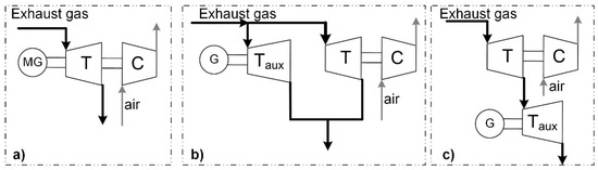
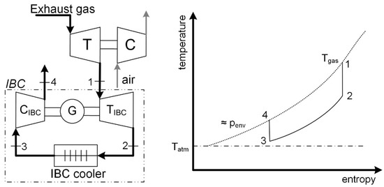
2. DHR via Inverted Brayton Cycle (IBC)
3. DHR via Thermoelectric Generation
4. IHR via Thermodynamic Cycles
4.1. Organic Rankine Cycles
The Organic Rankine Cycle (ORC) is by far the most studied opportunity in waste heat recovery: it is very similar to the steam Rankine cycle but uses a working fluid of an organic nature (Figure 3a,b). This consents to the recovery from low-grade thermal sources [59]. An ORC-based recovery unit is composed of a heat exchanger acting as an evaporator (or Heat Recovery Vapor Generator, HRVG, from section 2 to 3), an expander or turbine (state points 3–4), a condenser (4–1) and a pump (1–2). Some other components can be introduced for efficiency optimization or plant operability (such as a tank/reservoir, a bypass branch for the turbine, an internal heat exchanger for the regeneration stage, etc.) [60].
It is quite commercial for different applications (industrial, geothermal) but it has been studied only in recent years for the transportation sector, in particular for heavy-duty applications. For light-duty and passenger cars, the higher variability of the waste heat temperature and amount (for instance, exhaust mass flow rate) makes it difficult to implement a high-efficiency recovery plant in operating conditions [61].
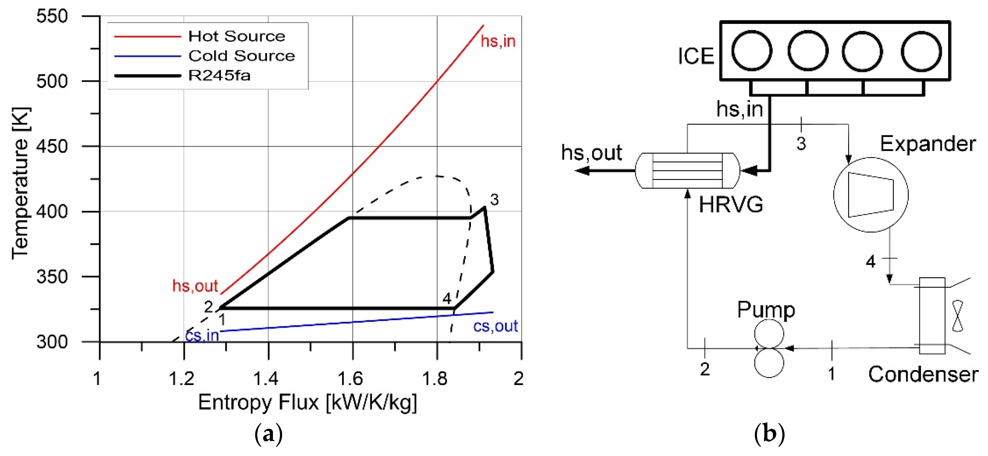
Figure 3. (a) base T-s diagram of an Organic Rankine Cycle bottomed to exhaust gas and using R245fa as working fluid (dashed line is the saturation curve of the fluid)); (b) base layout of ORC unit.
4.2. Trilateral Flash cycle (TFC)
Trilateral Flash Cycle (TFC), or Organic Flash Cycle (OFC), is a bottoming thermodynamic cycle particularly suitable for low-temperature waste heat recovery, around 80–100 °C [62][63]. The name “Trilateral” highlights the shape of the cycle, which is almost triangular (Figure 4) and it is particularly suitable for that kind of upper thermal sources that do not match with a Rankine or Hirn cycle. So, it can be interesting for very low temperature sources and limited flows of fluid cooling, or for cascade cycle, bottoming to a main recovery unit to further increase the final energy produced. The shape of the T-s diagram at the saturated liquid side can add some additional interest to the exploitation of this technology. It is based on a Rankine cycle in which the vaporization is not realized, but a saturated liquid is expanded. Hence, it is composed of a pump, a simple heat exchanger used to heat up the high pressure working fluid to the saturated liquid state and so, a wet expansion within the two-phase region and a final condensation [64].
The difficulties to recover energy in the two-phase region of the fluid (wet expansion) suggest using volumetric machines as expanders and, preferably, with a variable volume ratio [65]. As shown in Figure 4, the possibility to increase the exergy recovered is great (i.e., the closer the value of the TFC to the upper and lower thermal source/sink), but only if the expander efficiency is close to the one of a conventional turbine; TFC can compete with ORC in terms of final energetic efficiency [66]. More recently, the use of fluid mixtures has also been proposed to increase the efficiency of the OFC [67].
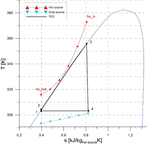
Figure 4. TFC T-S diagram [68]: transformation 1–2 is a pressurization in the liquid phase, 2–3 heating of the liquid, 3–4 is the wet expansion, 4–1 the condensation. Dark blue line is the saturation curve of the working fluid (R1234ze(E)).
4.3. Use of Zeotropic Mixtures as Working Fluids
The selection of working fluids is one of the most investigated issues. It should respect several constraints and parameters: low flammability, no toxicity, low ozone depletion potential and global warming potentials, as well as other low environmental impacts. At the same time, the working fluid should have high thermodynamic performances in relation to the upper and the lower thermal sources available. Dry and isentropic fluids are suitable for ORC-based units [69]. The opportunity to be mixed with lubricating oil is an additional positive issue because volumetric expanders which are very suitable for small-size recovery units need to be lubricated to improve mechanical and volumetric efficiencies.
In this regard, the opportunity to use zeotropic mixtures (i.e., mixtures of fluids, which can vary their temperature during phase change) can have the opportunity to better approach the thermal sources and sinks during evaporation and condensation of the working fluid, thanks to the temperature glide during phase transition (Figure 5) [70].

Figure 5: T-s diagram of an ORC with mixtures of working fluids [71]. Inset zoom on the temperature glide in the evaporation phase. Similar to the condensation one. Dashed line is the saturation curve of the fluid mixture (R245fa/benzene 0.95/0.05)
4.4. Cascade Cycles
When the temperature of the upper thermal source is enough high (>300 °C, for instance), only ORC is not suitable, since it introduces a high exergy destruction rate in the heat recovery vapor generator [72]. Indeed, the influence of the pinch point temperature on the energy recovered is significant and the differentiation of the layout can be proposed to increase the recovery efficiency [73]. In particular, the combination of more than one thermodynamic cycle can be used, in a cascade form [74], in order to match the upper thermal level with one recovery section, and the cold sink with a bottomed one, increasing the exergy efficiency of the overall recovery unit [75].
The use of the CO2 Brayton cycle is very popular, where the CO2 is performed in the supercritical phase (pc,CO2 = 74 bar). In particular, the CO2 is in a dense phase when it is close to the critical point, with a thermodynamic advantage in terms of fluid density (it has a density close to the one of a liquid and it has low viscosity like a gas, increasing the mass per unit volume without increasing pressure drops across ducts) and reduced viscosity with respect to a gas. Moreover, CO2 is a natural compound, stable, non-toxic and non-flammable, with a reduced environmental impact with respect to fluorinated gases. Thus, the supercritical CO2 (sCO2) topping cycle is bottomed by an ORC one, aimed to partially recover the thermal energy to be disposed of in the lower CO2 pressure side (Figure 6a, [75]), and a trade-off between the cycle efficiency and the heat recovery must be analyzed, [76]. Only a few sCO2 recovery plants have been manufactured and actually operated since this technology has not yet reached technical and commercial maturity [77]. Several configurations have been proposed in this regard (parallel, cascade [78], regenerative [79][80], re-heated and intercooled [81][82], recompression [83], dual expansion [84][85], etc.) in order to increase the net power output. The complexity of the recovery plant is shown in Figure 6b, where the two cascade sections are sketched. State points from 1 to 5 refer to sCO2 Brayton cycle, while 7 to 9 are referred to ORC one. The need for an additional heat exchanger (CO2 cooler after HRVG, from state points 5 to 1) is highlighted. The management of supercritical values of CO2 pressures can also represent a limiting factor, in particular for small-scale units, where the amount of recovery does not justify high-pressure components, piping, seals, etc., which in turn brings higher costs. In fact, the introduction of ORC as the bottoming cycle in combined recovery plants has been proposed also for medium-low temperature sources, to increase the overall energy recovered [86].
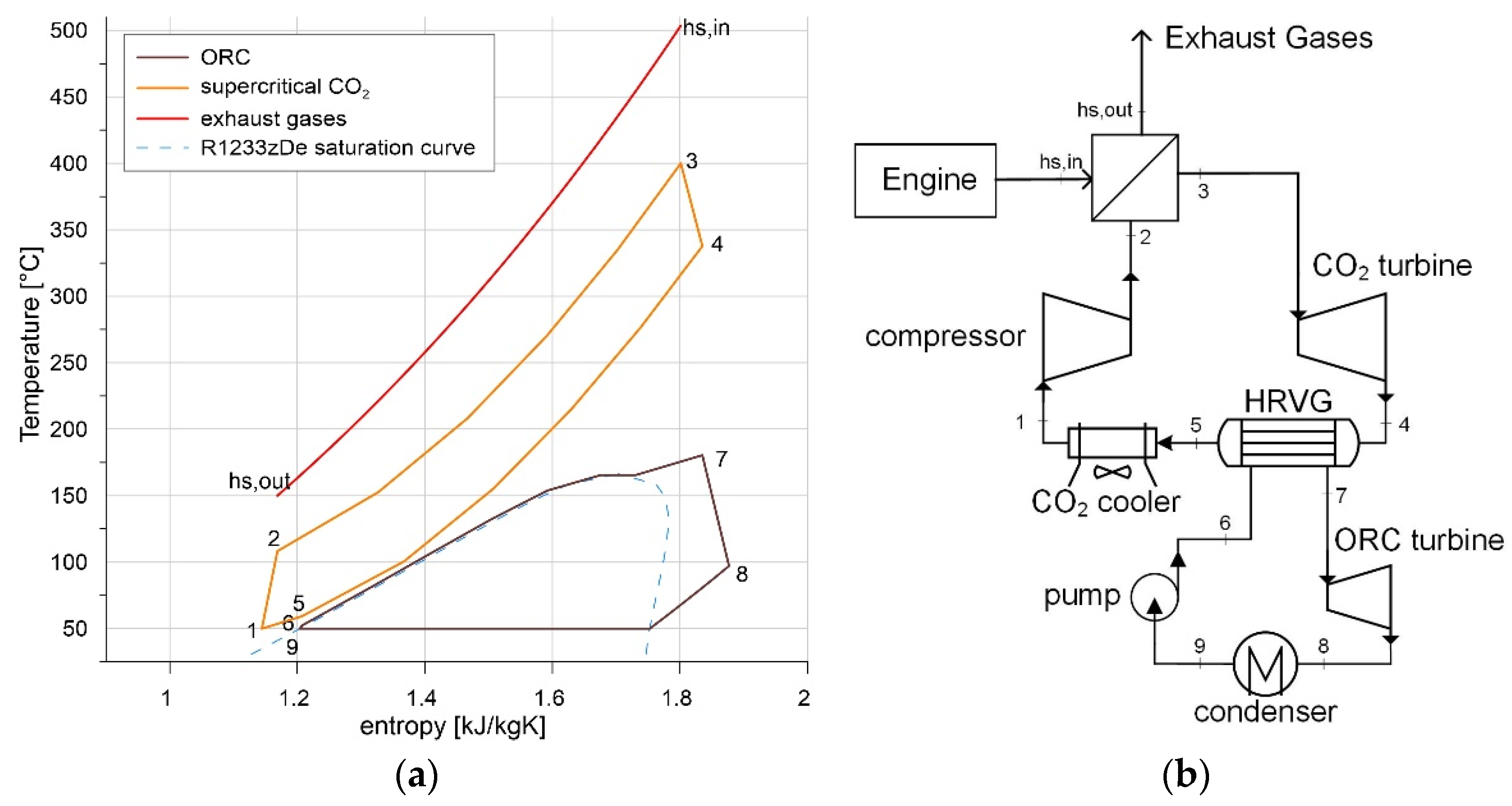
Figure 6. (a) example of T-s diagram of a combined energy recovery unit composed by supercritical CO2 and ORC [75]; (b) simple layout of sCO2+ ORC unit.
4.5. Stirling Cycle
Even though the Stirling engine was discovered in the early 1800s, only recently it has been applied in several applications, especially in combination with renewable sources and as a waste heat recovery option in industry [87][88]. The Stirling cycle is a gas engine cycle composed of two isotherms and two isochore lines as an indicator diagram. A regenerator is interposed in between. Its main advantage is that the Stirling cycle does not replace the working fluid for every cycle. The working gas can be air or other gases. The overall amount of thermal energy is supplied externally from the engine, making possible the use of any kind of source. Stirling engines can achieve high thermal efficiencies, ideally the one of the Carnot cycle, since the heat exchange takes place at a constant temperature. In reality, the transformations are usually far from the ideal ones, and the real efficiency does not overcome 20–25% during operation [89].
Stirling engines could be an interesting solution for ICE thanks to their compact design, easiness of management, application flexibility and the possibility to be adopted for different energy sources [90][91]. The power recoverable can range from hundreds of watts to kW. Different solutions of Stirling engines can be found, such as alpha, beta, and gamma configurations [92], single or double-acting cylinders [93], or free-piston operational mechanism [94].
5. Direct Heat Utilization
The thermal power recovered can be directly used for heating purposes, in particular for steady state applications in CHP mode. The first example usually considered, is cabin heating in automotive applications [95]: the heat removed from the engine by the coolant is partially used in a heat exchanger placed in the dashboard of the vehicle. This exchanger is crossed on one side by the hot coolant, exiting from the engine jackets, and by air on the second side, thanks to the controlled fan, which regulates the thermal power to be sent to the cabin interior. Often, the cabin heater lays in a branch of the cooling circuit in parallel with the radiator and the bypass branches, without undergoing thermostat control [96]. Additionally exhaust heat or lubricating heat can be used for this purpose, in order to optimize the thermal level [97][98]. Its integration with other thermal needs improves the overall efficiency of the system [99], for instance, accelerating the warming up of the lubricant oil, reducing frictions, and improving engine thermal management: the use of the exhaust to warm up the engine oil during cold phase demonstrated a fuel consumption reduction over 3% [100][101].
A different use of the thermal power to be disposed on board is represented by absorption chillers, which can improve the integration concept of thermal needs [102][103], feeding refrigeration, and cooling needs. Waste heat driven heat pumps can also allow low-temperature heating purposes [104][105]. The integration of absorption chillers on board can also be used for increasing the propulsion system efficiency, cooling the engine charge air [106], or optimizing the thermal management of electric devices [107][108]. In industrial applications, the integration of Rankine cycles with multiple-level refrigeration systems can meet the requirements of air-conditioning, refrigeration, and also cryogenic cooling, aiming at a full energy recovery of lost heat [109].
When applied to exhaust gases, the heat exchanger performance plays a crucial role: it should have high thermal efficiency to maximize the thermal exchange towards the working fluid of the recovery unit [110], and also in terms of backpressure increase on the engine, which should be significantly limited in order to avoid excessive overconsumption on the engine itself and tailpipe emissions [111]. The impacts of extra weight, additional cooling fan power consumption, transient control, effects on engine intake air management as well as exhaust after-treatment thermal inertia should be also considered in mobile applications [112].
References
- Castillo, F.; Witrant, E.; Dugard, L.; Talon, V. Exhaust Manifold Pressure Estimation Diesel Equipped with a VGT Turbocharger; SAE Technical Paper 2013-01-1752; SAE International: Warrendale, PA, USA, 2013.
- Chiara, F.; Canova, M.; Wang, Y.-Y. An exhaust manifold pressure estimator for a two-stage turbocharged Diesel engine. In Proceedings of the 2011 American Control Conference, San Francisco, CA, USA, 29 June–1 July 2011; pp. 1549–1554.
- Kozak, D.; Mazuro, P. Review of Small Gas Turbine Engines and Their Adaptation for Automotive Waste Heat Recovery Systems. Int. J. Turbomach. Propuls. Power 2020, 5, 8.
- Zhao, R.; Zhuge, W.; Zhang, Y.; Yang, M.; Martinez-Botas, R.; Yin, Y. Study of two-stage turbine characteristic and its influence on turbo-compound engine performance. Energy Convers. Manag. 2015, 95, 414–423.
- Callahan, T.J.; Branyon, D.P.; Forster, A.C.; Ross, M.G.; Simpson, D.J. Effectiveness of mechanical turbo compounding in a modern heavy-duty diesel engine. Int. J. Automot. Eng. 2012, 3, 69–73.
- Boretti, A. Conversion of a heavy duty truck diesel engine with an innovative power turbine connected to the crankshaft through a continuously variable transmission to operate compression ignition dual fuel diesel-LPG. Fuel Process. Technol. 2013, 113, 97–108.
- Grönman, A.; Sallinen, P.; Honkatukia, J.; Backman, J.; Uusitalo, A. Design and experiments of two-stage intercooled electrically assisted turbocharger. Energy Convers. Manag. 2016, 111, 115–124.
- Pasini, G.; Lutzemberger, G.; Frigo, S.; Marelli, S.; Ceraolo, M.; Gentili, R.; Capobianco, M. Evaluation of an electric turbo compound system for SI engines: A numerical approach. Appl. Energy 2016, 162, 527–540.
- Pipitone, E.; Caltabellotta, S. Efficiency Advantages of the Separated Electric Compound Propulsion System for CNG Hybrid Vehicles. Energies 2021, 14, 8481.
- Marelli, S.; Usai, V. Experimental Evaluation of the Performance of an Automotive Electric Supercharger; SAE Technical Paper 2020-37-0008; SAE International: Warrendale, PA, USA, 2020.
- Gamache, C.; Van Nieuwstadt, M.; Martz, J.; Zhu, G. Dual-output PID transient control of an electric-assisted air charge system. Int. J. Engine Res. 2023, 14680874231154964.
- Winward, E.; Rutledge, J.; Carter, J.; Costall, A.; Stobart, R.; Zhao, D.; Yang, Z. Performance testing of an electrically assisted turbocharger on a heavy duty diesel engine. In Proceedings of the 12th International Conference on Turbochargers and Turbocharging 2016, London, UK, 17–18 May 2016; pp. 363–382.
- Cipollone, R.; Di Battista, D.; Gualtieri, A. Direct heat recovery from the ICE exhaust gas. In Sustainable Vehicle Technologies; Woodhead Publishing: Soston, UK, 2012; pp. 177–187. ISBN 9780857094568.
- Cipollone, R.; Di Battista, D.; Gualtieri, A. Energy Recovery from the Turbocharging System of Internal Combustion Engines. In Proceedings of the ASME 2012 11th Biennial Conference on Engineering Systems Design and Analysis, Nantes, France, 2–4 July 2012; ASME: Houston, TX, USA, 2012; pp. 477–487.
- Kruiswyk, R.W. The role of turbocompound in the era of emissions reduction, IMechE. In Proceedings of the ASME 10th International Conference on Turbochargers and Turbocharging, London, UK, 15–16 May 2012; Woodhead Publishing: Soston, UK, 2012; pp. 269–280.
- Serrano, J.R.; Climent, H.; Piqueras, P.; Darbhamalla, A. Energy recovery potential by replacing the exhaust gases recirculation valve with an additional turbocharger in a heavy-duty engine. Energy Convers. Manag. 2022, 271, 116307.
- Mattarelli, E.; Scrignoli, F.; Rinaldini, C. Parametric Study on Electric Turbocharging for Passenger Cars; SAE Technical Paper 2020-01-2224; SAE International: Warrendale, PA, USA, 2020.
- Frigo, S.; Francesconi, M.; Sani, L.; Antonelli, M. Numerical analysis of energy recovery system for turbocharged internal combustion engines via a parallel compounding turbine. J. Phys. Conf. Ser. 2022, 2385, 012070.
- Thompson, I.G.M.; Spence, S.; McCartan, C.; Talbot-Weiss, J.; Thornhill, D. One Dimensional Modeling of a Turbogenerating Spark Ignition Engine Operating on Biogas. SAE Int. J. Engines 2011, 4, 1354–1364.
- Aghaali, H.; Ångström, H.-E. A review of turbocompounding as a waste heat recovery system for internal combustion engines. Renew. Sustain. Energy Rev. 2015, 49, 813–824.
- Marelli, S.; Usai, V.; Capobianco, M.; Montenegro, G.; Della Torre, A.; Onorati, A. Direct Evaluation of Turbine Isentropic Efficiency in Turbochargers: CFD Assisted Design of an Innovative Measuring Technique; SAE Technical Paper 2019-01-0324; SAE International: Warrendale, PA, USA, 2019.
- Kennedy, I.; Chen, Z.; Ceen, B.; Jones, S.; Copeland, C.D. Experimental Investigation of an Inverted Brayton Cycle for Exhaust Gas Energy Recovery. J. Eng. Gas Turbines Power 2018, 141, 032301.
- Wilson, D.G.; Dunteman, N.R. The Inverted Brayton Cycle for Waste-Heat Utilization. In Proceedings of the ASME 1973 International Gas Turbine Conference and Products Show, Washington, DC, USA, 8–12 April 1973; ASME: Houston, TX, USA, 1973.
- Alabdoadaim, M.; Agnew, B.; Potts, I. Performance analysis of combined Brayton and inverse Brayton cycles and developed configurations. Appl. Therm. Eng. 2006, 26, 1448–1454.
- Di Battista, D.; Fatigati, F.; Carapellucci, R.; Cipollone, R. Inverted Brayton Cycle for waste heat recovery in reciprocating internal combustion engines. Appl. Energy 2019, 253, 113565.
- Di Battista, D.; Cipollone, R.; Carapellucci, R. A Novel Option for Direct Waste Heat Recovery from Exhaust Gases of Internal Combustion Engines; SAE Technical Paper 2020-37-0004; SAE International: Warrendale, PA, USA, 2020.
- Copeland, C.D.; Chen, Z. The Benefits of an Inverted Brayton Bottoming Cycle as an Alternative to Turbo-Compounding. In Proceedings of the ASME Turbo Expo 2015: Turbine Technical Conference and Exposition, Montreal, QC, Canada, 15–19 June 2015; ASME: Houston, TX, USA, 2015; Volume 8.
- Chen, Z.; Copeland, C. Inverted Brayton Cycle Employment for a Highly Downsized Turbocharged Gasoline Engine; SAE Technical Paper 2015-01-1973; SAE International: Warrendale, PA, USA, 2015.
- Di Battista, D.; Carapellucci, R.; Cipollone, R. Integrated evaluation of Inverted Brayton cycle recovery unit bottomed to a turbocharged diesel engine. Appl. Therm. Eng. 2020, 175, 115353.
- Abrosimov, K.; Sciacchitano, F.; Pasini, G.; Baccioli, A.; Bischi, A.; Antonelli, M. Techno-economic analysis of waste heat recovery by inverted Brayton cycle applied to an LNG-fuelled transport truck. E3S Web Conf. 2021, 238, 10008.
- Chen, Z.; Copeland, C.; Ceen, B.; Jones, S.; Goya, A.A. Modeling and Simulation of an Inverted Brayton Cycle as an Exhaust-Gas Heat-Recovery System. J. Eng. Gas Turbines Power 2017, 139, 081701.
- Kennedy, I.; Chen, Z.; Ceen, B.; Jones, S.; Copeland, C.D. Inverted Brayton Cycle with Exhaust Gas Condensation. J. Eng. Gas Turbines Power 2018, 140, 111702.
- Di Battista, D.; Cipollone, R.; Carapellucci, R. Inverted Brayton Cycle as an Option for Waste Energy Recovery in Turbocharged Diesel Engine; SAE Technical Paper 2019-24-0060; SAE International: Warrendale, PA, USA, 2019.
- Abrosimov, K.; Baccioli, A.; Bischi, A. Extensive techno-economic assessment of combined inverted Brayton – Organic Rankine cycle for high-temperature waste heat recovery. Energy 2020, 211, 118406.
- Goodarzi, M. Energy and exergy analyses of a new atmospheric regenerative Brayton and Inverse Brayton cycle. Energy Rep. 2021, 7, 4530–4539.
- Matsui, K.; Thu, K.; Miyazaki, T. A hybrid power cycle using an inverted Brayton cycle with an indirect evaporative device for waste-heat recovery. Appl. Therm. Eng. 2020, 170, 115029.
- Salek, F.; Babaie, M.; Naserian, M.M.; Ahmadi, M.H. Power enhancement of a turbo-charged industrial diesel engine by using of a waste heat recovery system based on inverted Brayton and organic Rankine cycles. Fuel 2022, 322, 124036.
- Kaneko, K.; Ohtani, K.; Tsujikawa, Y.; Fujii, S. Utilization of the cryogenic exergy of LNG by a mirror gas-turbine. Appl. Energy 2004, 79, 355–369.
- Agelidou, E.; Henke, M.; Monz, T.; Aigner, M. Numerical Investigation of an Inverted Brayton Cycle Micro Gas Turbine Based on Experimental Data. In Proceedings of the ASME Turbo Expo 2018: Turbomachinery Technical Conference and Exposition, Oslo, Norway, 11–15 June 2018; ASME: Houston, TX, USA, 2018; Volume 3.
- Carapellucci, R.; Di Battista, D. Combined Brayton, Inverse Brayton and Steam Cycles Power Plant. In Proceedings of the ASME 2020 International Mechanical Engineering Congress and Exposition, Virtual, 16–19 November 2020; ASME: Houston, TX, USA, 2020; Volume 8.
- Bianchi, M.; Di Montenegro, G.N.; Peretto, A. Inverted Brayton Cycle Employment for Low-Temperature Cogenerative Applications. J. Eng. Gas Turbines Power 2002, 124, 561–565.
- Abrosimov, K.A.; Galkin, D.I.; Tumashev, R.Z.; Ustinov, A.A. Simulation of CHP System Based on Micro Gas Turbine with Inverted Brayton Cycle. In Proceedings of the ASME Turbo Expo 2017: Turbomachinery Technical Conference and Exposition, Charlotte, NC, USA, 26–30 June 2017; ASME: Houston, TX, USA, 2017; Volume 3.
- Armstead, J.R.; Miers, S.A. Review of Waste Heat Recovery Mechanisms for Internal Combustion Engines. J. Therm. Sci. Eng. Appl. 2013, 6, 014001.
- Liu, C.; Ye, W.; Li, H.; Liu, J.; Zhao, C.; Mao, Z.; Pan, X. Experimental study on cascade utilization of ship’s waste heat based on TEG-ORC combined cycle. Int. J. Energy Res. 2020, 45, 4184–4196.
- Nadaf, N.; Preethi, A. Review on Waste Heat Energy Harvesting using TEG: Applications and Enhancements. In Proceedings of the 2021 8th International Conference on Smart Computing and Communications: Artificial Intelligence, AI Driven Applications for a Smart World, ICSCC 2021, Kochi, India, 1–3 July 2021; pp. 334–339.
- Karri, M.; Thacher, E.; Helenbrook, B. Exhaust energy conversion by thermoelectric generator: Two case studies. Energy Convers. Manag. 2011, 52, 1596–16111.
- Liang, X.; Wang, X.; Shu, G.; Wei, H.; Tian, H.; Wang, X. A review and selection of engine waste heat recovery technologies using analytic hierarchy process and grey relational analysis. Int. J. Energy Res. 2014, 39, 453–471.
- Von Lukowicz, M.; Abbe, E.; Schmiel, T.; Tajmar, M. Thermoelectric Generators on Satellites—An Approach for Waste Heat Recovery in Space. Energies 2016, 9, 541.
- Quan, R.; Liang, W.; Quan, S.; Huang, Z.; Liu, Z.; Chang, Y.; Tan, B. Performance interaction assessment of automobile exhaust thermoelectric generator and engine under different operating conditions. Appl. Therm. Eng. 2022, 216, 119055.
- Karana, D.R.; Sahoo, R.R. Performance effect on the TEG system for waste heat recovery in automobiles using ZnO and SiO2 nanofluid coolants. Heat Transf. 2018, 48, 216–232.
- Borcuch, M.; Musiał, M.; Gumuła, S.; Wojciechowski, K.T. Performance parameters and numerical model of thermoelectric generator dedicated for energy harvesting from flue gases. J. Phys. Conf. Ser. 2016, 745, 032008.
- Sok, R.; Kusaka, J. Development and validation of thermal performances in a novel thermoelectric generator model for automotive waste heat recovery systems. Int. J. Heat Mass Transf. 2023, 202, 123718.
- Lan, S.; Stobart, R.; Chen, R. Performance comparison of a thermoelectric generator applied in conventional vehicles and extended-range electric vehicles. Energy Convers. Manag. 2022, 266, 115791.
- Liu, C.; Liu, J.; Ye, W.; Li, H.; Zhao, C.; Wang, H.; Xu, M.; Pan, X. Study on a new cascade utilize method for ship waste heat based on TEG-ORC combined cycle. Environ. Prog. Sustain. Energy 2021, 40, e13661.
- Zhang, W.; Yang, F.; Zhang, H.; Ping, X.; Yan, D. Numerical analysis and optimization design of fin-and-tube evaporator in organic Rankine cycle system for diesel engine waste heat recovery. Int. J. Heat Mass Transf. 2021, 175, 121376.
- Luo, J.; Lu, P.; Chen, K.; Luo, X.; Chen, J.; Liang, Y.; Yang, Z.; Chen, Y. Experimental and simulation investigation on the heat exchangers in an ORC under various heat source/sink conditions. Energy 2023, 264, 126189.
- Di Battista, D.; Mauriello, M.; Cipollone, R. Waste heat recovery of an ORC-based power unit in a turbocharged diesel engine propelling a light duty vehicle. Appl. Energy 2015, 152, 109–120.
- Di Battista, D.; Mauriello, M.; Cipollone, R. Effects of an ORC Based Heat Recovery System on the Performances of a Diesel Engine; SAE Technical Papers; SAE International: Warrendale, PA, USA, 2015.
- Kumar, A.; Rakshit, D. A critical review on waste heat recovery utilization with special focus on Organic Rankine Cycle applications. Clean. Eng. Technol. 2021, 5, 100292.
- Fatigati, F.; Vittorini, D.; Di Bartolomeo, M.; Cipollone, R. Experimental characterization of a small-scale solar Organic Rankine Cycle (ORC) based unit for domestic microcogeneration. Energy Convers. Manag. 2022, 258, 115493.
- Lion, S.; Michos, C.N.; Vlaskos, I.; Rouaud, C.; Taccani, R. A review of waste heat recovery and Organic Rankine Cycles (ORC) in on-off highway vehicle Heavy Duty Diesel Engine applications. Renew. Sustain. Energy Rev. 2017, 79, 691–708.
- Bianchi, G.; McGinty, R.; Oliver, D.; Brightman, D.; Zaher, O.; Tassou, S.A.; Miller, J.; Jouhara, H. Development and analysis of a packaged Trilateral Flash Cycle system for low grade heat to power conversion applications. Therm. Sci. Eng. Prog. 2017, 4, 113–121.
- Iqbal, A.; Rana, S.; Ahmadi, M.; Date, A.; Akbarzadeh, A. Experimental study on the prospect of low-temperature heat to power generation using Trilateral Flash Cycle (TFC). Appl. Therm. Eng. 2020, 172, 115139.
- Smith, I.K. Development of the Trilateral Flash Cycle System: Part 1: Fundamental Considerations. Proc. Inst. Mech. Eng. Part A J. Power Energy 1993, 207, 179–194.
- Bianchi, G.; Marchionni, M.; Miller, J.; Tassou, S.A. Modelling and off-design performance optimisation of a trilateral flash cycle system using two-phase twin-screw expanders with variable built-in volume ratio. Appl. Therm. Eng. 2020, 179, 115671.
- Yari, M.; Mehr, A.; Zare, V.; Mahmoudi, S.; Rosen, M. Exergoeconomic comparison of TLC (trilateral Rankine cycle), ORC (organic Rankine cycle) and Kalina cycle using a low grade heat source. Energy 2015, 83, 712–722.
- Wu, S.; Ma, Y.; Yang, Z.; Miao, Z. Thermodynamic Analysis and Optimization of Organic Flash Cycle Using Zeotropic Mixtures Working Fluids. Zhongguo Dianji Gongcheng Xuebao/Proc. Chin. Soc. Electr. Eng. 2022, 42, 7546–7553.
- Cipollone, R.; Bianchi, G.; Di Bartolomeo, M.; Di Battista, D.; Fatigati, F. Low grade thermal recovery based on trilateral flash cycles using recent pure fluids and mixtures. Energy Procedia 2017, 123, 289–296.
- Zhang, X.; Zhang, Y.; Wang, J. New classification of dry and isentropic working fluids and a method used to determine their optimal or worst condensation temperature used in Organic Rankine Cycle. Energy 2020, 201, 117722.
- Miao, Z.; Li, Z.; Zhang, K.; Xu, J.; Cheng, Y. Selection criteria of zeotropic mixtures for subcritical organic Rankine cycle based on thermodynamic and thermo-economic analysis. Appl. Therm. Eng. 2020, 180, 115837.
- Di Battista, D.; Cipollone, R.; Villante, C.; Fornari, C.; Mauriello, M. The Potential of Mixtures of Pure Fluids in ORC-based Power Units fed by Exhaust Gases in Internal Combustion Engines. Energy Procedia 2016, 101, 1264–1271.
- Cipollone, R.; Di Battista, D.; Bettoja, F. Performances of an ORC power unit for Waste Heat Recovery on Heavy Duty Engine. Energy Procedia 2017, 129, 770–777.
- Van Erdeweghe, S.; Van Bael, J.; Laenen, B.; D’haeseleer, W. Influence of the pinch-point-temperature difference on the performance of the Preheat-parallel configuration for a low-temperature geothermally-fed CHP. Energy Procedia 2017, 129, 10–17.
- Ren, X.; Li, J.; Pei, G.; Li, P.; Gong, L. Parametric and economic analysis of high-temperature cascade organic Rankine cycle with a biphenyl and diphenyl oxide mixture. Energy Convers. Manag. 2023, 276, 116556.
- Di Battista, D.; Fatigati, F.; Carapellucci, R.; Cipollone, R. An improvement to waste heat recovery in internal combustion engines via combined technologies. Energy Convers. Manag. 2021, 232, 113880.
- Giuffrida, A.; Akramieh, E. Analysis of partial heating supercritical CO2 cycles bottoming small-power gas turbine units. Energy Convers. Manag. X 2023, 17, 100341.
- Alfani, D.; Binotti, M.; Macchi, E.; Silva, P.; Astolfi, M. sCO2 power plants for waste heat recovery: Design optimization and part-load operation strategies. Appl. Therm. Eng. 2021, 195, 117013.
- Crespi, F.; Gavagnin, G.; Sánchez, D.; Martínez, G.S. Supercritical carbon dioxide cycles for power generation: A review. Appl. Energy 2017, 195, 152–183.
- Chacartegui, R.; Sanchez, D.; Jimenez-Espadafor, F.; Munoz, A.; Sanchez, T. Analysis of intermediate temperature combined cycles with a carbon dioxide topping cycle. In Proceedings of the ASME Turbo Expo 2008: Power for Land, Sea, and Air, Berlin, Germany, 9–13 June 2008; American Society of Mechanical Engineers: New York, NY, USA; pp. 673–680.
- Wu, C.; Yan, X.J.; Wang, S.S.; Bai, K.L.; Di, J.; Cheng, S.F.; Li, J. System optimisation and performance analysis of CO2 transcritical power cycle for waste heat recovery. Energy 2016, 100, 391–400.
- Moisseytsev, A.; Sienicki, J.J. Investigation of alternative layouts for the supercritical carbon dioxide Brayton cycle for a sodium-cooled fast reactor. J. Eng. Power 2009, 239, 1362–1371.
- Turchi, C.S.; Ma, Z.; Neises, T.W.; Wagner, M.J. Thermodynamic Study of Advanced Supercritical Carbon Dioxide Power Cycles for Concentrating Solar Power Systems. J. Sol. Energy Eng. 2013, 135, 041007.
- Akbari, A.D.; Mahmoudi, S.M.S. Thermoeconomic analysis & optimization of the combined supercritical CO2 (carbon dioxide) recompression Brayton/organic Rankine cycle. Energy 2014, 78, 501–512.
- Manente, G.; Fortuna, F.M. Supercritical CO2 power cycles for waste heat recovery: A systematic comparison between traditional and novel layouts with dual expansion. Energy Convers. Manag. 2019, 197, 111777.
- Ahn, Y.; Bae, S.J.; Kim, M.; Cho, S.K.; Baik, S.; Lee, J.I.; Cha, J.E. Review of supercritical CO2 power cycle technology and current status of research and development. Nucl. Eng. Technol. 2015, 47, 647–661.
- Sarkar, J. Review and future trends of supercritical CO2 Rankine cycle for low-grade heat conversion. Renew. Sustain. Energy Rev. 2015, 48, 434–451.
- Durcansky, P.; Nosek, R.; Jandačka, J. Use of Stirling Engine for Waste Heat Recovery. Energies 2020, 13, 4133.
- Jiang, Z.; Yu, G.; Zhu, S.; Dai, W.; Luo, E. Advances on a free-piston Stirling engine-based micro-combined heat and power system. Appl. Therm. Eng. 2022, 217, 119187.
- Douadi, O.; Ravi, R.; Faqir, M.; Essadiqi, E. A conceptual framework for waste heat recovery from compression ignition engines: Technologies, working fluids & heat exchangers. Energy Convers. Manag. X 2022, 16, 100309.
- Walker, G. Stirling Engines; Clarendon Press: Oxford, UK; Oxford University Press: New York, NY, USA, 1980.
- Hachem, H.; Gheith, R.; Aloui, F.; Ben Nasrallah, S. Technological challenges and optimization efforts of the Stirling machine: A review. Energy Convers. Manag. 2018, 171, 1365–1387.
- Güven, M.; Bedir, H.; Anlaş, G. Optimization and application of Stirling engine for waste heat recovery from a heavy-duty truck engine. Energy Convers. Manag. 2018, 180, 411–424.
- Cheng, C.-H.; Tan, Y.-H.; Liu, T.-S. Experimental and Dynamic Analysis of a Small-Scale Double-Acting Four-Cylinder α-Type Stirling Engine. Sustainability 2021, 13, 8442.
- Perozziello, C.; Grosu, L.; Vaglieco, B.M. Free-Piston Stirling Engine Technologies and Models: A Review. Energies 2021, 14, 7009.
- Jaybhay, S.; Nagarhalli, P.; Kapoor, S. Practical Approach to Develop Low Cost, Energy Efficient Cabin Heating for Extreme Cold Operating Environment. SAE Int. J. Mater. Manuf. 2011, 4, 216–230.
- Di Bartolomeo, M.; Di Battista, D.; Cipollone, R. Experimentally based methodology to evaluate fuel saving and CO2 reduction of electrical engine cooling pump during real driving. SAE J. Engines 2023, 16.
- Xu, Y.; Yan, Z.; Xia, W. A novel system for aircraft cabin heating based on a vapor compression system and heat recovery from engine lubricating oil. Appl. Therm. Eng. 2022, 212, 118544.
- Muthusamy, P.; Kumar, P.S. Waste Heat Recovery Using Matrix Heat Exchanger from the Exhaust of an Automobile Engine for Heating Car’s Passenger Cabin. Adv. Mater. Res. 2014, 984-985, 1132–1137.
- Li, L.; Liu, Z.; Deng, C.; Xie, N.; Ren, J.; Sun, Y.; Xiao, Z.; Lei, K.; Yang, S. Thermodynamic and exergoeconomic analyses of a vehicular fuel cell power system with waste heat recovery for cabin heating and reactants preheating. Energy 2022, 247, 123465.
- Di Battista, D.; Cipollone, R. Improving Engine Oil Warm Up through Waste Heat Recovery. Energies 2017, 11, 10.
- Kim, T.; Natarajan, D. Fuel-to-Warm Methodology: Optimization Tool for Distributing Waste Heat during Warm-Up within the Powertrain System; SAE Technical Paper 2021-01-0210; SAE International: Warrendale, PA, USA, 2021.
- Butrymowicz, D.; Gagan, J.; Łukaszuk, M.; Śmierciew, K.; Pawluczuk, A.; Zieliński, T.; Kędzierski, M. Experimental validation of new approach for waste heat recovery from combustion engine for cooling and heating demands from combustion engine for maritime applications. J. Clean. Prod. 2020, 290, 125206.
- Hemmati, S.; Doshi, N.; Hanover, D.; Morgan, C.; Shahbakhti, M. Integrated cabin heating and powertrain thermal energy management for a connected hybrid electric vehicle. Appl. Energy 2020, 283, 116353.
- Lajunen, A.; Yang, Y.; Emadi, A. Review of Cabin Thermal Management for Electrified Passenger Vehicles. IEEE Trans. Veh. Technol. 2020, 69, 6025–6040.
- Cho, C.-W.; Lee, H.-S.; Won, J.-P.; Lee, M.-Y. Measurement and Evaluation of Heating Performance of Heat Pump Systems Using Wasted Heat from Electric Devices for an Electric Bus. Energies 2012, 5, 658–669.
- Vittorini, D.; Di Bartolomeo, M.; Di Battista, D.; Cipollone, R. Charge Air Subcooling in a Diesel Engine via Refrigeration Unit—Effects on the Turbocharger Equilibrium. Energy Procedia 2018, 148, 822–829.
- Zhang, C.-W.; Xu, K.-J.; Li, L.-Y.; Yang, M.-Z.; Gao, H.-B.; Chen, S.-R. Study on a Battery Thermal Management System Based on a Thermoelectric Effect. Energies 2018, 11, 279.
- Hong, S.H.; Jang, D.S.; Park, S.; Yun, S.; Kim, Y. Thermal performance of direct two-phase refrigerant cooling for lithium-ion batteries in electric vehicles. Appl. Therm. Eng. 2020, 173, 115213.
- Khaliq, A. Performance analysis of a waste-heat-powered thermodynamic cycle for multieffect refrigeration. Int. J. Energy Res. 2014, 39, 529–544.
- Ravi, R.; Pachamuthu, S.; Kasinathan, P. Computational and experimental investigation on effective utilization of waste heat from diesel engine exhaust using a fin protracted heat exchanger. Energy 2020, 200, 117489.
- Ravi, R.; Pachamuthu, S. Design and Development of Innovative Protracted-Finned Counter Flow Heat Exchanger (PFCHE) for an Engine WHR and Its Impact on Exhaust Emissions. Energies 2018, 11, 2717.
- Wu, X.; Zhang, N.; Xie, L.; Ci, W.; Chen, J.; Lu, S. Thermoeconomic Optimization Design of the ORC System Installed on a Light-Duty Vehicle for Waste Heat Recovery from Exhaust Heat. Energies 2022, 15, 4486.

