Your browser does not fully support modern features. Please upgrade for a smoother experience.
Submitted Successfully!
 +1 credit
Thank you for your contribution! You can also upload a video entry or images related to this topic.
For video creation, please contact our Academic Video Service.
| Version | Summary | Created by | Modification | Content Size | Created at | Operation |
|---|---|---|---|---|---|---|
| 1 | Nediljka Gaurina-Međimurec | -- | 4311 | 2023-04-04 11:18:50 | | | |
| 2 | Catherine Yang | -8 word(s) | 4303 | 2023-04-06 03:44:48 | | | | |
| 3 | Catherine Yang | -1 word(s) | 4302 | 2023-04-06 03:45:36 | | |
Video Upload Options
We provide professional Academic Video Service to translate complex research into visually appealing presentations. Would you like to try it?
Cite
If you have any further questions, please contact Encyclopedia Editorial Office.
El Sabeh, K.; Gaurina-Međimurec, N.; Mijić, P.; Medved, I.; Pašić, B. Drilling Fluids for Extended-Reach Wells. Encyclopedia. Available online: https://encyclopedia.pub/entry/42775 (accessed on 27 July 2026).
El Sabeh K, Gaurina-Međimurec N, Mijić P, Medved I, Pašić B. Drilling Fluids for Extended-Reach Wells. Encyclopedia. Available at: https://encyclopedia.pub/entry/42775. Accessed July 27, 2026.
El Sabeh, Karim, Nediljka Gaurina-Međimurec, Petar Mijić, Igor Medved, Borivoje Pašić. "Drilling Fluids for Extended-Reach Wells" Encyclopedia, https://encyclopedia.pub/entry/42775 (accessed July 27, 2026).
El Sabeh, K., Gaurina-Međimurec, N., Mijić, P., Medved, I., & Pašić, B. (2023, April 04). Drilling Fluids for Extended-Reach Wells. In Encyclopedia. https://encyclopedia.pub/entry/42775
El Sabeh, Karim, et al. "Drilling Fluids for Extended-Reach Wells." Encyclopedia. Web. 04 April, 2023.
Copy Citation
In the planning phase of extended-reach well (ERW), special attention should be paid to the choice of drilling fluid. Selected drilling fluids for extended-reach wells should satisfy the same basic functions that are common to all drilling fluids, and they have to provide excellent reservoir protection. When drilling extended-reach wells, the following critical factors should be considered: hole cleaning, torque and drag, borehole stability, equivalent circulating density (ECD) and lost circulation. So far, oil-based mud (OBM) and water-based mud (WBM) have also been used in practice, but the emphasis is on the application of environmentally friendly additives.
well design
extended-reach drilling (ERD)
torque
drag
hole cleaning
barite sag
ECD
drilling fluid
1. Hole Cleaning
Drilling fluid has many functions, and one of the primary functions is to carry drilled cuttings to the surface. To achieve that goal, it is necessary to remove them quickly and efficiently. In doing so, it is important to keep in mind that hole cleaning depends on a number of parameters, such as (1) the hole angle of the interval, (2) flow rate/annular velocity, (3) drilling fluid rheology and density, (4) cutting size, shape, density and integrity, (5) rate of penetration (ROP), (6) drill string rotational rate and (7) drill string eccentricity [1][2][3][4]. It is also important to emphasize that effective hole cleaning does not depend on only one drilling parameter but also on a combination of parameters [4]. Bilgesu et al. (2007) divided key factors in drill cuttings transport into three main groups: (a) operational factors, (b) drilling fluid parameters and (3) cuttings parameters. Operational factors include drill pipe rotation, hole inclination, annular eccentricity and the fluid flow rate. The parameters of the drilling fluid refer to its density, rheological parameters and composition. Cutting parameters are their shape, size and type. Only a few of them can be effectively controlled during drilling for hole-cleaning purposes. Poor hole cleaning has led to over 70% lost time in oil and gas drilling operations [2][5].
Unlike vertical wells, in directional, extended-reach wells, there are three cleaning zones that differ from each other according to the hole inclination. These are the I zone (0–30°), II zone (30–60°) and III zone (60–90°) (Figure 1a). As soon as the deviation in the borehole channel exceeds 10°, there is a tendency for cuttings to deposit on the lower walls of that channel. With an increasing inclination, this tendency is more pronounced. However, in practice, the greatest tendency toward the deposition of cuttings was observed in the third zone, at an inclination between 30° and 60° [6].
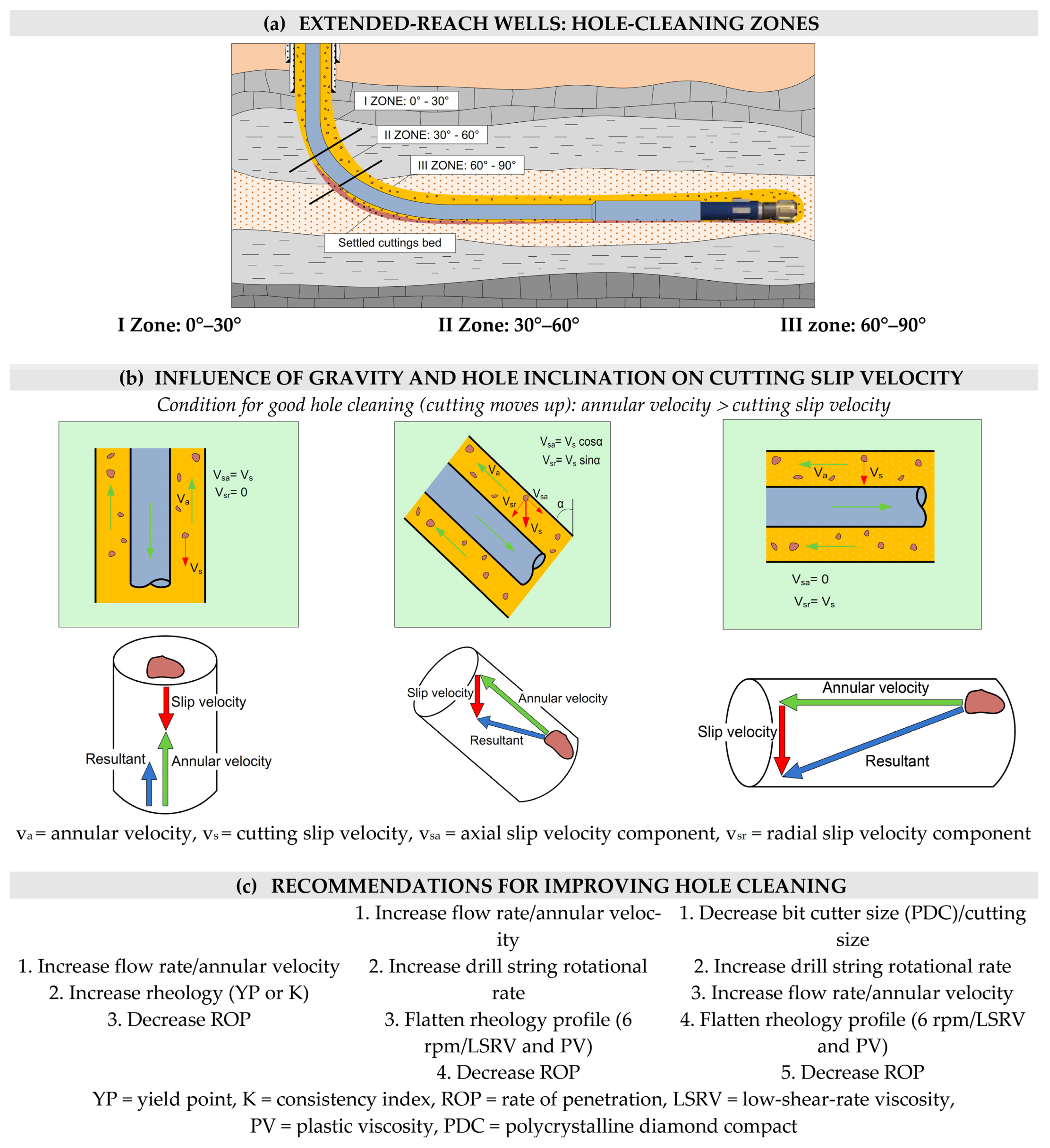
Figure 1. Hole cleaning in extended-reach wells (cleaning zones (a), influence of gravity and hole inclination (b) and recommendations for improving (c)).
During the hole cleaning, the cuttings are affected by positive forces upwards (due to the mud velocity, viscosity and density) and negative forces downwards (due to the action of gravity) (Figure 1b).
Cuttings fall or slide through parts of the mud column that do not move (or move slowly) and will fall faster through muds of a lower viscosity than through viscous muds. In order to achieve the satisfactory removal of cuttings from the bottom and bring them to the surface, the annular mud velocity should be slightly higher than the rate of the sliding of the cuttings (cuttings slip velocity, settling velocity) through the mud column toward the bottom of the wellbore. Recommendations for improving the hole cleaning of each zone are presented in Figure 1c.
The annular velocity has the greatest influence on cleaning holes from cuttings in almost vertical (Zone I) and moderately inclined intervals of holes (Zone II), whereas, in extended-reach, high-angle wells (Zone III), it ranks third in importance (Figure 1c). Increasing the flow rate or using a drill pipe with a larger outer diameter (OD) results in a higher annular velocity. In practice, a slight improvement in hole cleaning was observed at an annular rate greater than 60.96 m/min (200 ft/min), but an increase in the equivalent circulating density (ECD) occurred [7]. Unfortunately, increasing the annular velocity increases the flow resistances and hence the ECD, so the flow rate must be balanced to achieve satisfactory cutting transport and to minimize the formation of cutting layers (beds) without creating an excessive ECD.
In Zone I, a laminar flow with a high yield point value and low plastic viscosity (Bingham plastic fluids) or high consistency index value and low flow index value (power-law fluids) will produce a flat viscosity profile and efficiently carry cuttings out of the hole. The yield point may be adjusted with appropriate additives without changing the plastic viscosity significantly. A low plastic viscosity and flat rheological profiles can be achieved if drilled solids are removed from the drilling fluid at the surface using appropriate solid control equipment to maintain a low drilled solid content in the drilling fluid. If the drilled cuttings are not removed, the plastic viscosity will continue to increase as the drilled cuttings are ground into smaller particles. Large cuttings will separate from the drilling fluid faster than smaller cuttings, but, in high-angle holes, even smaller cuttings may settle and form a cuttings layer [3]. For the efficient transportation of small cuttings during extended-reach drilling, the rotation of the drill pipe in combination with polymer drilling fluid is highly recommended [8]. Pipe rotation can significantly improve hole cleaning, particularly when the drill pipe is eccentric, because effective hole cleaning is not possible with axial flow alone [9].
In zones II and III cuttings, under the action of gravity, they tend to fall through the mud to the lower walls of the hole from which they are only a few millimeters away and form a layer of cuttings. Preventing rock cuttings accumulating on the lower side of the ERD wells is much easier than removing them.
The formation of the cutting bed will be reduced or mitigated if the following are applied: a higher flow rate/annular velocity, higher drill string rotational rate, flatter rheology profile (6 rpm/LSRV and PV) and reduced ROP. The thickness of the cuttings bed will increase from 0.21 m to 0.28 m with an increase in ROP from 15 m/h to 40 m/h [6].
Once a layer of cuttings is formed, an attempt should be made to remove it from the hole. This can be achieved by applying a low-viscosity pill to disturb the cuttings bed, followed by high-density pills (sweeps) of low-viscosity fluid, coupled with pipe rotation. Pipe rotation aids the cuttings removal process, greatly reducing the thickness of the cuttings layer for both low-viscosity and high-viscosity drilling fluids, especially if the pipe is fully eccentric [10]. In the absence of drill pipe rotation, in order to clean cuttings out of a wellbore when drilling is stopped, using water or low-viscosity mud is better than using high-viscosity mud [11].
In horizontal and highly inclined wellbores, drag forces are the main forces that lead to the cuttings bed erosion. Drag forces are higher than the lift forces, which helps to explain the reason why it is more difficult to remove cuttings that have already been embedded in the cuttings bed [12].
Adari et al. (2000) investigated the cuttings bed height as a function of time by using different flow rates (0.76–1.52 m3/min; 200–400 gpm) and four different compositions of the drilling fluid, and concluded that: (a) the erosion of the cuttings bed occurs faster as the drilling fluid flow rate increases, (b) for a given drilling fluid flow rate, a lower cuttings bed height is achieved as the n/K ratio increases, (c) cuttings removal is easier with turbulent flow than with laminar flow, and (d) cuttings accumulation in the wellbore and thus the circulation time required to clean the wellbore from cuttings increases as the inclination of the well increases. The thickness of the cuttings bed has a significant effect on the annular pressure gradient [3][13].
The rotation of the drill pipe not only reduces the solid concentration in annulus but also increases the migration rate of the solid phase, thereby promoting horizontal well cleaning [14]. As the drill string rotates faster, the pipe drags more fluid with it. In deviated and extended-reach wells, this layer of drilling fluid disrupts any debris deposits that have formed around the pipe as it lies on the low side of the well and tends to move it uphole [15]. The drill pipes in ERD are not centered but eccentric, resulting in a high velocity in the upper part of the well and a low velocity in the lower part of the well below the drill pipes. Cuttings are transported better at a high velocity, but the gravity tends to cause the cuttings to fall into the low-velocity area. Moving and rotating the pipe is the only way to transport cuttings into the upper part of the hole above the drill pipes to improve hole cleaning. Creating turbulent flow around the drill pipe can reduce the formation of debris deposits and improve the process of hole cleaning.
Generally, reducing ROP improves hole cleaning. Therefore, the current penetration rate should be controlled so that it is not too large no excessive volume of cuttings is created. In this way, the drilling fluid is given sufficient time to remove the intact cuttings from the bottom of the well, thus reducing the accumulation of cuttings and avoiding overloading the annular with them.
In order to improve the hole cleaning of the wellbore, there are several methods used in ERD wells, such as optimizing debris removal using real-time annulus pressure measurements during drilling, where real-time annulus pressure monitoring can be used to reduce the risk and optimize the drilling process, especially in extended-reach applications. Field data show how real-time pressure data are used interactively to optimize debris removal and adjust the mud weight. The ability to monitor and subsequently control circulating well pressure allows for narrow acceptance windows between the estimated pore pressure and fracture gradient [16].
The use of downhole mechanical cleaning devices (MCDs) has been introduced into the petroleum industry to alleviate the problem without causing excessive ECD. Recently, hydro-mechanical downhole-cleaning devices such as Hydroclean tools have been developed to increase the efficiency of cuttings transport in directional wells.
Hole cleaning depends on several factors and, to date, most of the existing models have been applied to solve the problem of hole cleaning. However, the flow rate pre-dicted by these models may not be feasible for practical application in field operations because it produces a pressure that exceeds allowable limits of the pop-up valves on the mud pump. This is a major cause of downtime during well drilling. Dosumnu (2015) developed a model to keep track of the cuttings removal in order to achieve adequate hole cleaning and reduce the non-productive time [17].
The model has the capacity to determine the amount of cuttings collected while drilling in real time, thereby ensuring a reduced non-productive time while ensuring drilling safety as well as the target depth objective. This is possible as a direct quantitative measurement of hole cleaning and hole stability is vital information for reaching these three objectives [17].
Today’s needs for larger amounts of hydrocarbons have forced the industry to increase production and thus to improve the way in which oil and gas reservoirs are exploited. The construction of horizontal wells enables the exploitation of oil and gas reservoirs that have been unavailable or economically unprofitable so far, such as the exploitation of reservoirs with a small thickness, the exploitation of reservoirs located under environmentally sensitive areas, etc. Although drilling technology is constantly developing, there are still issues with drilling that occur, and especially with extended-reach wells.
2. Torque and Drag
The torque or moment is generally the force multiplied by the lever arm. When we talk about torque and drilling, torque is the moment required to rotate the pipe. Torque is used to overcome rotational friction in the well and on the bit. Torque is lost from the rotating string, so less torque is available at the bit for destroying rock. Actual torque and drag values measured in the field are always influenced by other factors. Some of these can be modeled, while other effects are lumped together into the fudge factor, which we call the friction factor, which is not the same as the friction coefficient as in pure kinetic sliding friction. The combined effect of all of these parameters is what gives the total torque and drag forces. In general, we can separate drag forces that are the result of hole cleaning or inappropriate mud design and drag forces associated with the well path [18].
There are several causes of excessive torque and drag, including tight hole conditions, sloughing hole, key seats, differential sticking, cuttings build-up caused by poor hole cleaning and sliding wellbore friction [19].
In extended-reach wells, both in the curved and in the horizontal part of the well, the torsion and drag of drill string are usually larger and there is a tendency for the drill string to lie on the lower wall of the wellbore. Therefore, more complex cleaning conditions are present in ERWs than in vertical and slightly inclined wells.
Torque and drag are important and serious issues for any extended-reach well as they can impose severe limitations on drilling operations. They are affected by many factors, such as the well trajectory design, drilling fluid type, hole size, drill string design and hole cleaning.
The deposition and accumulation of cuttings on the lower wall of the curved part, and especially the horizontal part, of the wellbore contribute to the unfavorable cleaning of the wellbore, with the eccentric position of the drilling tools in relation to the axis of the wellbore.
In addition, the cuttings bed increases the frictional drag and limits the possibility of weight transfer to the bit. This results in an increased possibility of a jammed and stuck pipe, loss of mud, wellbore instability and impossibility or difficulty in well logging and running and/or casing cementing. A reduction or even elimination of these hazards can be achieved by appropriate rheological properties of the mud and a suitable flow regime of the selected mud.
The process of reducing torque and drag is a combination of many different meth-ods. Only one method usually does not solve the problems. In order to reduce torque and drag, several methods may have to be applied at the same time, such as: an optimized well plan, bit selection, drill string design, use of rotary steerable system, use of modular motor, use of non-rotating drillpipe protectors, use of mud additives and proper hole cleaning [20].
The first step in the drilling process design is having an optimized drilling assembly that includes the selection of each particular part of the drill string capable of avoiding any excess in torque and drag. Buster et al. described the performance of High Torque OCTG Premium Connection developed for extended-reach wells with long intervals (˃6000 ft) that utilize a thread and coupled design that has an excellent torque capacity [21].
The desire to reduce torque and drag has led to the development of many products that have been successfully applied in practice such as fibrous lost circulation material and glass beads. Numerous lubricants are available on the market that are added to the drilling fluid to reduce the coefficient of friction. According to field experience, a typical lubricant reduces the coefficient of friction by approximately 20%, and a high-performance lubricant by up to 50% [22]. The friction reduction performance of the lubricant for coiled tubing (CT) application in ERWs depends on its concentration and on the presence of polyacrylamide (a viscosifer and fluid friction reducer), salt and sand in the fluid. Laboratory tests have shown that polyacrylamide in a concentration greater than 1% adversely affects the performance of the lubricant while, when increasing the lubricant concentration, the friction coefficient decreases, which is especially pronounced at higher salinity and sand conditions [22].
Besides adding lubricants to the drilling fluid, another solution for additional torque reduction is the use of different mechanical tools. Schamp et al. studied and analyzed the use of mechanical tools to reduce torque in ERD wells. The use of mechanical torque reduction tools consisting of an inner mandrel and an outer sleeve on two wells resulted in significant torque reduction [23].
3. Equivalent Circulating Density
The equivalent circulating density (ECD) is a combination of the static drilling fluid density and annular pressure loss. The ECD and hole cleaning are inter-related: poor hole cleaning can increase the ECD. The amount of particles present in the drilling fluid increases its density and thus the ECD. In addition, extended-reach wells are characterized by their long horizontal displacement. The annular pressure loss increases when increasing the annulus length, resulting in a continuous increase in the ECD with the measured depth (MD). This is a problem when the formation pressure gradient/fracture gradient window is narrow. The flow rate can be limited to control the annular pressure loss and reduce the ECD, but this can affect the quality of cuttings transport and cause a fluctuation in the ECD. which can cause formation fracturing and a loss of circulation. The presence of cuttings increases the pressure drop due to the reduction in the flow area inside the wellbore. An increase in the annular pressure loss was observed with a high pipe rotation speed in an eccentric annulus [10]. In the absence of cuttings, frictional pressure losses increase as the pipe rotation speed increases, but, in the presence of cuttings, due to a reduction in the stationary area of the cuttings bed, frictional pressure losses may decrease [24].
The open-hole limit of an extended-reach well (the greatest measured depth of the horizontal ERW) mainly depends on the pressure drop in the annulus and the fracture pressure of the drilled formation [25].
4. Barite Sag
Barite sag occurs when the mud is not circulated for a long time. However, it has been shown that a barite sag can form during circulation and can be thicker than when the flow is static. This process can be accelerated by slow circulating rates, casing running and wire line logging. In extended-reach wells, barite deposition can lead to wellbore mud losses, mud weight fluctuations, a stuck pipe and wellbore instability. This is una-voidable but can be managed through a combination of good operating procedures and drilling fluid design. A low shear rate viscosity is a critical factor in achieving good hole cleaning and avoiding barite settling [26]. In drilling ERWs, barite sag can be minimized or mitigated by increasing the low shear rate viscosity (LSRV) of the drilling fluid, rotating the drill pipe and using micronized weight materials.
5. Drilling Fluid Selection
Drilling fluid is extremely important for successful extended-reach drilling (ERD), so it should be chosen especially carefully in order to meet technical, economic and environmental requirements. Historically, oil or synthetic-based muds have tended to be the fluids of choice [26]. ERD drilling fluids are designed to generate a flatter rheological performance to reduce the effect of fluid rheology on the ECD. When selecting drilling fluids for extended-reach wells in areas that are particularly environmentally sensitive, the selection of drilling fluids should take into account technical and environmental criteria regarding the processing and disposal of cuttings and spent drilling fluid.
Oil-based fluids have been observed in the field to be better at removing cuttings from horizontal wells compared to water-based fluids with similar rheological properties [27][28].
Oil-based muds (drilling fluids) (OBMs) include: a true oil-based mud containing 90–95% diesel oil and 5–10% water emulsified within the oil, an invert emulsion mud containing 60–90% oil and 10–40% water emulsified within the oil, emulsion muds (oil-in-water mud) and synthetic-based mud (SBM) that has a synthesized liquid base (polyalphaolefins (PAO), linear alphaolefins (LAOs), straight internal olefins (IOs), esters, vegetable oils and ethers). Various additives such as viscosifiers, emulsifiers, weighting material and other additives are added to the base fluid to adjust its properties and produce a stable and efficient fluid that will meet the requirements in specific well conditions.
In Western Siberia, oil-based mud was chosen in drilling a 152.4 mm horizontal section on the Samburgskoye field [29]. It provided optimal rheological parameters for shale inhibition, hole stability and lubricity. The implementation of an oil-based drilling fluid system was justified by the longer lateral section to be drilled. In addition, it helped to improve the RSS steerability and borehole quality [29].
Invert emulsion mud can be formulated with mineral oil or other low-environmental-risk oil substitutes when necessary. In this mud, water and chemicals are used together to control the fluid loss and plastic viscosity. Invert emulsion muds (also known as non-aqueous fluids, NAFs) are the most commonly used oil mud. Invert emulsions generally provide an excellent cuttings integrity, good hole protection and a low coefficient of friction. The latter allows for easier rotation and, in extended-reach drilling, greater flow around the underside side of the drill string. Their use has been a key driver of successful extended-reach drilling and hydrocarbon access [30].
Synthetic-based muds share several advantages with traditional oil-based muds, including improved drilling rates, excellent wellbore stability, reduced torque, good hole cleaning and excellent cuttings integrity. The main advantage of SBMs compared to traditional OBMs is the reduced impact of cuttings and liquid mud on the environment.
By applying increasing environmental restrictions and stricter regulations, the oil industry has been forced to develop water-based inhibited fluid technology, combined with suitable lubricants, that can replace invert emulsion muds.
For extended-reach drilling, the most suitable water-based drilling fluids are those based on potassium, polymer mud with silicates or glycol [31]. These types of drilling fluids are used when shale inhibition is required. Mixed-metal silicates can be used if shale inhibition is not required. Drilling fluids for ERD wells are designed to provide a flatter rheological profile to reduce the effect of the fluid rheology on the equivalent circulating density (ECD) [26].
To maximize the cuttings removal from the hole, new formulations of water-based muds were developed with the addition of different additives, such as: polymer beads (polyethylene, polypropylene), fibers (monofilament synthetic, polypropylene monofilament, cellulose nanofibers and natural hydrated basil seeds), nanoparticles, bio-based additives and a fuzzy ball [28]. The polymer beads improve the hydrodynamic resistance within the drilling fluid, leading to an increase in the drag coefficient. The fibers are dispersed in sweep fluids to form a stable network structure due to their entanglement. The fiber network prevents cuttings settling by mechanical contact and hydrodynamic interference between cuttings and fibers, and thus improves the drilling fluid carrying capacity. Bio-based additives and organic oils have been proposed to reduce the environmental impact of water-based muds and oil-based muds.
So far, both oil-based mud (OBM) and water-based muds (WBMs) have been used in practice, as well as the depth and assembly used to drill each of the wells. Table 1 and Table 2 summarize available data for 30 extended-reach wells drilled worldwide on 18 production fields.
Table 1. The main information about the analyzed extended-reach wells.
| Source | Well | Field | Location | KOP (m) | Measured Depth (MD), m | True Vertical Depth (TVD), m | MD/TVD | Drilling Assembly | Mud Type |
|---|---|---|---|---|---|---|---|---|---|
| Lemons and Craig, 1989. [32] | H-13 | P-0203 block | California, USA | 183 | 3901 | 1877 | 2.08 | N/A | N/A |
| Morgan and Jiang, 1998; Jiang and Nian, 1998. [33][34] | A 14 | N/A | South China Sea | 427 | 9238 | approx 2750 m | 3.36 | kick sub on mud motor | water-based |
| Meader et al., 2000. [35] | M-16 | Wytch Farm | England coast | N/A | 11,278 | approx 1700 m | 6.63 | steerable motor | oil-based |
| Mason et al., 2003. [36] | PN1y | Harding | North Sea | 150 | 6950 | 1676 | 4.15 | - | - |
| PN1w | 150 | 7771 | 1762 | 4.41 | RSS | oil-based | |||
| WN1 | 150 | 7621 | 1792 | 4.25 | RSS | oil-based | |||
| A 16 | Chirag | Caspian Sea | 400 | 7604 | 2800 | 2.72 | RSS | oil-based | |
| A16 T2 | 400 | 7280 | 2750 | 2.65 | RSS | oil-based | |||
| A17 | 200 | 6383 | 2780 | 2.30 | RSS | oil-based | |||
| A18 | 650 | 9586 | 2730 | 3.51 | RSS | oil-based | |||
| Schamp et al., 2006. [23] | typical | Chayvo | Sakhalin, Russia | approx 200 | 9100–11,134 | approx 3000 | 3.03–3.71 | RSS | oil-based |
| Sonowal et al., 2009. [37] | BD-04A | Al-Shaheen | Qatar | approx 300 | 12,289 | approx 1100 | 11.17 | RSS | oil-based |
| Mirhaj et al., 2010. [38] | N/A | N/A | North Sea | approx 350 | 5247 | N/A | - | RSS | water-based |
| Walker, 2012. [39] | OP-11 | Odoptu | Sakhalin, Russia | 180 | 12,345 | 1784 | 6.92 | - | - |
| Walker et al., 2009. [40] | Z-12 | Chayvo | Sakhalin, Russia | 200 | 11,680 | 2600 | 4.49 | RSS | oil-based, synthetic-based |
| Gupta et al., 2013. [41] | Z-44 | Chayvo | Sakhalin, Russia | N/A | 12,376 | approx 2300 | 5.38 | RSS | oil-based |
| Okot et al., 2015. [42] | A | Manifa | Saudi Arabia | N/A | 8950 | approx 3650 | 2.45 | RSS | oil-based, synthetic-based |
| Muñoz et al., 2015. [43] | M-1 | N/A | Saudi Arabia | 275 | 11,293 | approx 2500 | 4.52 | - | oil-based |
| Kretsul et al., 2015. [29] |
N/A | Samburgkoye | Western Siberia, Russia | approx 2150 | 4371 | approx 3250 | 1.34 | RSS | oil-based |
| Ahn, 2015. [44] | Control | N/A | N/A | 2118 | 5262 | N/A | - | RSS | oil-based |
| A | 3012 | 6096 | N/A | - | - | - | |||
| B | 1993 | 4434 | N/A | - | - | - | |||
| Buster et al., 2016. [21] | typical | Eagle Ford | USA | 1829–3048 | 4877–6096 | 1829–3048 | 2–2.67 | - | - |
| Martinez et al., 2017. [45] | Perla-9 | Perla | Venezuela | 207 | 4660 | 2887 | 1.61 | - | oil-based |
| Golenkin et al., 2020 [46] | 12 | Yury Korchagin | Caspian Sea | N/A | 6061 | 1571 | 3.86 | - | - |
| 13 | N/A | 6390 | 1573 | 4.06 | - | - | |||
| 15 | N/A | 4684 | 1572 | 2.98 | - | - | |||
| Vasquez Bautista et al., 2019. [47] | N/A | G | Oman | N/A | approx 3600 | 1078 | 3.34 | - | - |
| Hussain et al., 2021. [48] | A-36 A | Brage | North Sea | approx 350 | 8800 | 2210 | 3.98 | RSS | water-based |
| A-36 B | approx 350 | 9000 | 2079 | 4.33 | RSS | water-based and oil-based |
Table 2. The construction of the analyzed extended-reach wells.
| Source | Well | Conductor | Surface Casing | Intermediate Casing I | Intermediate Casing II | Production Casing/liner | ||||||
|---|---|---|---|---|---|---|---|---|---|---|---|---|
| Diameter, mm (in) | Length, m | Diameter, mm (in) | Length, m | Diameter, mm (in) | Length, m | Diameter, mm (in) | Length, m | Diameter, mm (in) | Length, m | Liner Shoe MD, m | ||
| Lemons and Craig, 1989. [32] | H-13 | 508 (20) | 133 | 406.4 (16) | 469 | 339.725 (13 3/8) |
1806 | - | - | 244.475 (9 5/8) |
3482 | - |
| Morgan and Jiang, 1998; Jiang and Nian, 1998. [33][34] | A 14 | 609.6 (24) | 205 | 473.075 (18 5/8) |
398 | 339.725 (13 3/8) |
1728 | 244.475 (9 5/8) |
6752 | 177.8 (7) liner |
2578 | 8552 |
| Meader et al., 2000. [35] | M-16 | - | - | 473.075 (18 5/8) |
260 | 339.725 (13 3/8) |
1008 | 244.475 (9 5/8) |
7450 | 177.8 (7) liner |
2921 | 10,210 |
| Mason et al., 2003. [36] | PN1y | - | - | 339.725 (13 3/8) |
2285 | 273.05 × 244.475 (10 3/4 × 9 5/8) |
4663 | - | - | - | - | - |
| PN1w | 2285 | 5486 | ||||||||||
| WN1 | 2237 | 5384 | ||||||||||
| A 16 | 1373 | 6231 | ||||||||||
| A16 T2 | 1373 | 244.475 (9 5/8) |
5907 | |||||||||
| A17 | 1377 | 5006 | ||||||||||
| A18 | 3166 | 6420 | ||||||||||
| Schamp et al., 2006. [23] | typical | - | - | 473.075 (18 5/8) |
800 | 346.075 (13 5/8) |
3300 | 244.475 (9 5/8) |
7800–9600 | 168.275 or 177.8 (6 5/8 or 7) liner |
1300–3200 | 9375–10,900 |
| Sonowal et al., 2009. [37] | BD-04A | 508 (20) | 176 | 339.725 (13 3/8) |
897 | 244.475 (9 5/8) |
1485 | - | - | - | - | - |
| Mirhaj et al., 2010. [38] | N/A | 660.4 (26) | 350 | 339.725 (13 3/8) |
- | 244.475 (9 5/8) |
- | - | - | 177.8 (7) |
1680 | - |
| Walker, 2012. [39] | OP-11 | - | - | 473.075 (18 5/8) |
800 | 346.075 (13 5/8) |
5254 | - | - | 244.475 (9 5/8) liner |
5652 | 10,758 |
| Walker et al., 2009. [40] | Z-12 | 762 (30) | 97 | 473.075 (18 5/8) |
801 | 339.725 (13 3/8) |
3313 | - | - | 244.475 (9 5/8) |
8019 | - |
| Gupta et al., 2013. [41] | Z-44 | - | - | 473.075 (18 5/8) |
800 | 346.075 (13 5/8) |
4551 | - | - | 244.475 (9 5/8) liner |
4450 | 8883 |
| Okot et al., 2015. [42] | A | - | - | 473.075 (18 5/8) |
317 | 346.075 (13 5/8) |
1491 | 244.475 (9 5/8) |
3411 | 177.8 (7) liner |
4176 | 7262 |
| Muñoz et al., 2015. [43] | M-1 | - | - | 473.075 (18 5/8) |
275 | 339.725 (13 3/8) |
1850 | 244.475 (9 5/8) |
3375 | 177.8 (7) liner |
5548 | 8608 |
| Kretsul et al., 2015. [29] |
N/A | - | - | 339.725 (13 3/8) |
450 | 244.475 (9 5/8) |
1200 | - | - | 177.8 (7) |
3586 | - |
| Ahn, 2015. [44] | Control | - | - | - | - | - | - | - | - | 114.3 (4 1/2) |
5262 | - |
| B | 4434 | - | ||||||||||
| A | - | - | - | - | 177.8 (7) |
3297 | - | - | 114,3 (4 1/2) |
3223 | - | |
| Buster et al., 2016. [21] | typical | 339.725 (13 3/8)–508 (20) |
45 | 244.475 (9 5/8) |
1524–1829 | 193.675 (7 5/8) |
305–1220 | - | - | 139.7 (5 1/2) |
4877–6096 | - |
| Martinez et al., 2017. [45] | Perla-9 | 762 (30) | 202 | 508 (20) | 642 | 339.725 (13 3/8) |
1893 | 244.475 (9 5/8) liner |
2008 | 127 (5) liner | 4585 | 889 |
| Golenkin et al., 2020 [46] | 12 | - | - | - | - | 273.05 (10 3/4) |
2587 | - | - | 177.8 (7) |
3273 | - |
| 13 | - | - | - | - | 273.05 (10 3/4) |
2114 | - | - | 177.8 (7) |
3526 | - | |
| 15 | - | - | - | - | 273.05 (10 3/4) |
2303 | - | - | 177.8 (7) |
2464 | - | |
| Vasquez Bautista et al., 2019. [47] | N/A | 473.075 (18 5/8) |
50 | 339.725 (13 3/8) |
229 | 244.475 (9 5/8) |
approximately 1250 | - | - | 177.8 (7) liner |
- | - |
| Hussain et al., 2021. [48] | A-36 A | 711.2 (28) |
315 | 473.075 (18 5/8) |
1615 | 339.725 (13 3/8) |
1394 | 273.05 (10 3/4) |
- | 219.075 (8 5/8) liner |
- | - |
| A-36 B | 711.2 (28) |
315 | 473.075 (18 5/8) |
1615 | 339.725 (13 3/8) |
4574 | 273.05 (10 3/4) liner |
- | 219.075 (8 5/8) liner |
- | 6935 | |
References
- Ozbayoglu, M.E.; Miska, S.Z.; Reed, T.; Takach, N. Analysis of the Effects of Major Drilling Parameters on Cuttings Transport Efficiency for High-Angle Wells in Coiled Tubing Drilling Operations. In Proceedings of the SPE/ICoTA Coiled Tubing Conference and Exhibition, Houston, TX, USA, 23–24 March 2004.
- Ogunrinde, J.O.; Dosunmu, A. Hydraulic Optimization for Efficient Hole Cleaning in Deviated and Horizontal Wells. In Proceedings of the 2012 SPE Nigerian Annual International Conference and Exhibition, Abuja, Nigeria, 6–8 August 2012.
- Adari, R.B.; Miska, S.; Kuru, E.; Bern, P.; Saasen, A. Selecting Drilling Fluid Properties and Flow Rates for Effective Hole Cleaning in High-Angle and Horizontal Wells. In Proceedings of the SPE Annual Technical Conference and Exhibition, Dallas, TX, USA, 1–4 October 2000.
- Ofei, T.N.; Irawan, S.; Pao, W. Drilling Parameter Effects on Cuttings Transport in Horizontal Wellbores: A Review. ICIPEG 2014, 2015, 199–207.
- Bilgesu, H.I.; Mishra, N.; Ameri, S. Understanding the Effect of Drilling Parameters on Hole Cleaning in Horizontal and Deviated Wellbores Using Computational Fluid Dynamics. In Proceedings of the 2007 SPE Eastern Regional Meeting, Lexington, KY, USA, 17–19 October 2007.
- Zou, L.; Patel, M.H.; Han, G. A New Computer Package for Simulating Cuttings Transport and Predicting Hole Cleaning in Deviated and Horizontal Wells. In Proceedings of the SPE International Oil and Gas Conference and Exhibition, Beijing, China, 7–10 November 2000.
- Reeves, M.; Macpherson, J.D.; Zaeper, R.; Bert, D.R.; Shursen, J.; Armagost, W.K.; Paxton, D.S.; Hernandez, M. High Speed Drill String Telemetry Network Enables New Real Time Drilling and Measurement Technologies. In Proceedings of the IADC/SPE 99134, IADC/SPE Drilling Conference, Miami, FL, USA, 21–23 February 2006.
- Duan, M.; Miska, S.Z.; Yu, M.; Takach, N.E.; Ahmed, R.M.; Zettner, C.M. Transport of Small Cuttings in Extended-Reach Drilling. SPE Drill. Complet. 2008, 23, 258–265.
- Hemphill, T.; Ravi, K. Pipe Rotation and Hole Cleaning in an Eccentric Annulus. In Proceedings of the IADC/SPE Drilling Conference, Miami, FL, USA, 21–23 February 2006.
- Sorgun, M.; Aydin, I.; Ozbayoglu, M.E. Friction Factor for Hydraulic Calculations Considering Presence of Cuttings and Pipe Rotation in Horizontal / Highly-Inclined Wellbores. J. Pet. Sci. Eng. 2011, 78, 407–414.
- Valluri, S.G.; Miska, S.Z.; Ahmed, R.; Yu, M.; Takach, N. Experimental Study of Effective Hole Cleaning Using “Sweep” in Horizontal Wellbores. In Proceedings of the SPE Annual Technical Conference and Exhibition, San Antonio, TX, USA, 24–27 September 2006.
- Pedrosa, C.; Saasen, A.; Ytrehus, J.D. Fundamentals and Physical Principles for Drilled Cuttings Transport—Cuttings Bed Sedimentation and Erosion. Energies 2021, 14, 545.
- Singh, R.; Ahmed, R.; Karami, H.; Nasser, M.; Hussein, I. CFD Analysis of Turbulent Flow of Power-Law Fluid in a Partially Blocked Eccentric Annulus. Energies 2021, 14, 731.
- Wang, Z.; Guo, X.; LI, M.; Hong, Y. Effect of Drillpipe Rotation on Borehole Cleaning for Extended Reach Well. J. Hydrodyn. 2009, 21, 366–372.
- Gavignet, A.; Sobey, I.J. Model Aids Cuttings Transport Prediction. J. Pet. Technol. 1989, 41, 916–921.
- Pedersen, B.R.; Zajaczkowski, J. Optimization of Cuttings Removal by Use of Real-Time Annulus Pressure Measurements While Drilling. In Proceedings of the SPE Annual Technical Conference and Exhibition, New Orleans, LA, USA, 27–30 September 1998.
- Dosunmu, A.; Orun, C.; Anyanwu, C.; Ekeinde, E. Optimization of Hole Cleaning Using Dynamic Real-Time Cuttings Monitoring Tools. In Proceedings of the SPE Nigeria Annual International Conference and Exhibition, Lagos, Nigeria, 4–6 August 2015.
- Tveitdal, T. Torque and Drag Analysis of North Sea Well Using New 3D Model. Master’s Thesis, University of Stavanger, Stavanger, Norway, June 2011.
- Johanscik, C.A.; Friesen, D.B.; Dawson, P. Torque and Drag in Directional Wells-Prediction and Measurement. In Proceedings of the SPE 11380, IADC/SPE Drilling Conference, New Orleans, LA, USA, 20–23 February 1984.
- Çağlayan, B.K. Torque and Drag Applications for Deviated and Horizontal Wells: A Case Study. Master’s Thesis, Middle East Technical University, Ankara, Turkey, December 2014.
- Buster, J.; Perkins, J.; Azeredo, L. Development of Next Generation High Torque OCTG Premium Connection for Extended Reach Wells. In Proceedings of the Abu Dhabi International Petroleum Exhibition & Conference, Abu Dhabi, United Arab Emirates, 7–10 November 2016.
- Yeung, J.; Li, J.; Lee, J.; Guo, X. Evaluation of Lubricants Performance for Coiled Tubing Application in Extended Reach Well. In Proceedings of the SPE/ICoTA Coiled Tubing and Well Intervention Conference and Exhibition, Houston, TX, USA, 21–22 March 2017. SPE-184810-MS.
- Schamp, J.H.; Estes, B.L.; Keller, S.R. Torque Reduction Techniques in ERD Wells. In Proceedings of the IADC/SPE Drilling Conference, Miami, FL, USA, 21–23 February 2006.
- Ozbayoglu, M.E.; Saasen, A.; Sorgun, M.; Svanes, K. Effects of Pipe Rotation on Hole Cleaning for Water-Based Drilling Fluids in Horizontal and Deviated Wells. In Proceedings of the IADC/SPE Asia Pacific Drilling Technology Conference and Exhibition, Jakarta, Indonesia, 25–27 August 2008.
- Li, X.; Gao, D.; Zhou, Y.; Zhang, H.; Yang, Y. Study on the prediction model of the open-hole extended-reach limit in horizontal drilling considering the effects of cuttings. J. Nat. Gas Sci. Eng. 2017, 40, 159–167.
- Cameron, C. Drilling Fluids Design and Management for Extended Reach Drilling. In Proceedings of the IADC/SPE Middle East Drilling Technology Conference, Bahrain, 22–24 October 2001.
- Sayindla, S.; Lund, B.; Ytrehus, J.D.; Saasen, A. Hole-cleaning performance comparison of oil-based and water-based drilling fluids. J. Pet. Sci. Eng. 2017, 159, 49–57.
- Mahmoud, H.; Hamza, A.; Nasser, M.S.; Hussein, I.A.; Ahmed, R.; Karami, H. Hole cleaning and drilling fluid sweeps in horizontal and deviated wells: Comprehensive review. J. Pet. Sci. Eng. 2019, 186, 106748.
- Kretsul, V.; Dymov, S.; Dobrokhleb, P.; Milenkiy, A.; Tarasov, O. Technology Evolution Brings a New Step in Efficiency, Unlocks New Opportunities for Drilling Extended Laterals in the Samburgskoye Field. In Proceedings of the SPE Russian Petroleum Technology Conference, Moscow, Russia, 26–28 October 2015.
- Morrison, A.; Serov, N.; Ahmed, F. Completing Ultra Extended-Reach Wells: Overcoming the Torque and Drag Constraints of Brine. In Proceedings of the Abu Dhabi International Petroleum Exhibition & Conference, Abu Dhabi, United Arab Emirates, 11–14 November 2019.
- Gupta, A. Planning and Identifying Best Technologies for ERD Wells. In Proceedings of the SPE/IADC 102116, SPE/IADC Indian Drilling Technology Conference and Exhibition, Mumbai, India, 16–18 October 2006; pp. 1–6.
- Lemons, R.; Craig, M. Drilling Operations Planning and Drill Deck Strengthening for Extended-Reach Wells from an Existing Platform. In Proceedings of the Offshore Technology Conference, Houston, TX, USA, 1–4 May 1989.
- Jiang, Z.M.; Nian, Z.W. Critical Aspects Experienced in Drilling a World Record Extended Reach Well an South China Sea. In Proceedings of the SPE International Oil and Gas Conference and Exhibition in China, Beijing, China, 2–6 November 1998.
- Morgan, D.R.; Jiang, Z.M. Unique Aspects Encountered Drilling a Record Setting Extended Reach Well in China. In Proceedings of the Offshore Technology Conference, Houston, TX, USA, 4–7 May 1998.
- Meader, T.; Allen, F.; Riley, G. To the Limit and Beyond-The Secret of World-Class Extended-Reach Drilling Performance at Wytch Farm. In Proceedings of the IADC/SPE Drilling Conference, New Orleans, LA, USA, 23–25 February 2000.
- Mason, C.J.; Lopez, J.; Meling, S.; Munger, R.; Fraser, B. Casing Running Challenges for Extended-Reach Wells. In Proceedings of the SPE Annual Technical Conference and Exhibition, Denver, CO, USA, 5–8 October 2003.
- Sonowal, K.; Bennetzen, B.; Wong, K.M.; Erhan, I. How Continuous Improvement Lead to the Longest Horizontal Well in the World. In Proceedings of the SPE/IADC Drilling Conference and Exhibition, Amsterdam, The Netherlands, 17–19 March 2009.
- Mirhaj, S.A.; Fazaelizadeh, M.; Kaarstad, E.; Aadnoy, B.S. New aspects of torque-and-drag modeling in extended-reach wells. In Proceedings of the SPE Annual Technical Conference and Exhibition, Florence, Italy, 19–22 December 2010.
- Walker, M.W. Pushing the Extended Reach Envelope at Sakhalin: An Operator’s Experience Drilling a Record Reach Well. In Proceedings of the IADC/SPE Drilling Conference and Exhibition, San Diego, CA, USA, 6–8 March 2012.
- Walker, M.W.; Veselka, A.J.; Shane, A.H. Increasing Sakhalin Extended Reach Drilling and Completion Capability. In Proceedings of the SPE/IADC Drilling Conference and Exhibition, Amsterdam, The Netherlands, 17–19 March 2009.
- Gupta, V.P.; Sanford, S.R.; Mathis, R.S.; DiPippo, E.K.; Egan, M.J. Case History of a Challenging Thin Oil Column Extended Reach Drilling (ERD) Development at Sakhalin. In Proceedings of the SPE/IADC Drilling Conference, Amsterdam, The Netherlands, 5–7 March 2013.
- Okot, M.; Dubais, J.; Al-Hajji, A.; Chima, J.; Deschamps, B.; Elrefaei, I. Innovative Rotatable Friction Reduction Tool Applies Extra Force to Deploy Longest 7 in Liner in Saudi Arabia. In Proceedings of the SPE Middle East Oil & Gas Show and Conference, Manama, Bahrain, 8–11 March 2015.
- Muñoz, G.; Campos, M.; Mousa, A.; Osman, A.; Elsadig, M.; Al-Massari, B.; Askar, O.; Verma, V.; Almry, F. Pushing the Limit for Extended Reach Drilling: Delivering the Longest Well in Saudi Arabia and the Worldwide Deepest 6 1/8-in Section. In Proceedings of the Abu Dhabi International Petroleum Exhibition and Conference, Abu Dhabi, United Arab Emirates, 9–12 November 2015.
- Ahn, J. Achieving Economically Successful Coiled Tubing Composite Plug Drillouts in Extended Reach Wells. In Proceedings of the SPE/ICoTA Coiled Tubing & Well Intervention Conference & Exhibition, The Woodlands, TX, USA, 24–25 March 2015.
- Martinez, R.; Scotto, M.; Mendez, G.; Santaniello, F.; Reda, M.; Rojas, F.; Bustos, F.; Tang, J.; Rojas, J.; Borges, S.; et al. MPD Applicaton on ERD Well Offshore Venezuela–Managing Bottom Hole Pressure within Narrow Window in a Faulted Limestone Formation with a Static Underbalanced Drilling Fluid. In Proceedings of the SPE/IADC Drilling Conference and Exhibition, The Hague, The Netherlands, 14–16 March 2017.
- Golenkin, M.Y.E.; Biakov, A.P.; Eliseev, D.V.; Zavyalov, A.A.; Zhirkina, A.A.; Pico, Y.L.; Shapovalov, A.P.; Bulygin, I.A.; Yakovlev, I.M. The First for Russian Oil Company State of Art Intelligent Completion System Real Time Cleanup Monitoring and Optimization for 3 ERD wells in Caspian Offshore. In Proceedings of the SPE Russian Petroleum Technology Conference, Virtual, 26–29 October 2020.
- Vasquez Bautista, R.O.; Busaidi, A.A.; Awadalla, M.; Hawy, A.E.; Rawahi, Q.; Haeser, P.; Naamani, H.; Rashdi, H.A. Successfully Drilling the Longest Shallow ERD Wells in the Sultanate of Oman. In Proceedings of the SPE/IATMI Asia Pacific Oil & Gas Conference and Exhibition, Bali, Indonesia, 29–31 October 2019.
- Hussain, S.; Dahroug, M.S.; Mikalsen, B.; Christensen, K.H.; Nketah, D.N.; Monterrosa, L.; Van Aerssen, M.; Angell-Olsen, F.; Midttun, M.; Rouxinol, R.; et al. Enabling Technologies Help Drilling an Extreme ERD Well on Brage Field, North Sea. In Proceedings of the SPE/IADC International Drilling Conference and Exhibition, Virtual, 8–12 March 2021.
More
Information
Subjects:
Engineering, Petroleum
Contributors
MDPI registered users' name will be linked to their SciProfiles pages. To register with us, please refer to https://encyclopedia.pub/register
:
View Times:
3.0K
Revisions:
3 times
(View History)
Update Date:
06 Apr 2023
Table of Contents


Notice
You are not a member of the advisory board for this topic. If you want to update advisory board member profile, please contact office@encyclopedia.pub.
OK
Confirm
Only members of the Encyclopedia advisory board for this topic are allowed to note entries. Would you like to become an advisory board member of the Encyclopedia?
Yes
No
${ textCharacter }/${ maxCharacter }
Submit
Cancel
Back
Comments
${ item }
|
${ item.createdUser.fullName }
${ item.createdAt }
${ item.vote }
${ item.reply }
Delete
${ reply.createdUser.fullName }
${ reply.createdAt }
${ reply.vote }
Delete
There is no reply to this comment~
${ item.replyTextCharacter }/${ item.replyMaxCharacter }
Submit
Cancel
More
No more~
There is no comment~
${ textCharacter }/${ maxCharacter }
Submit
Cancel
${ selectedItem.replyTextCharacter }/${ selectedItem.replyMaxCharacter }
Submit
Cancel
Confirm
Are you sure to Delete?
Yes
No