Your browser does not fully support modern features. Please upgrade for a smoother experience.
Submitted Successfully!
 +1 credit
Thank you for your contribution! You can also upload a video entry or images related to this topic.
For video creation, please contact our Academic Video Service.
| Version | Summary | Created by | Modification | Content Size | Created at | Operation |
|---|---|---|---|---|---|---|
| 1 | Sven Bose | -- | 3252 | 2023-03-22 17:08:10 | | | |
| 2 | Sirius Huang | Meta information modification | 3252 | 2023-03-23 02:29:42 | | |
Video Upload Options
We provide professional Academic Video Service to translate complex research into visually appealing presentations. Would you like to try it?
Cite
If you have any further questions, please contact Encyclopedia Editorial Office.
Wacker, J.; Kloska, T.; Linne, H.; Decker, J.; Janes, A.; Huxdorf, O.; Bose, S. Adhesive Joint Design for Hybrid Automotive Wheel. Encyclopedia. Available online: https://encyclopedia.pub/entry/42442 (accessed on 25 June 2026).
Wacker J, Kloska T, Linne H, Decker J, Janes A, Huxdorf O, et al. Adhesive Joint Design for Hybrid Automotive Wheel. Encyclopedia. Available at: https://encyclopedia.pub/entry/42442. Accessed June 25, 2026.
Wacker, Jens-David, Tobias Kloska, Hannah Linne, Julia Decker, Andre Janes, Oliver Huxdorf, Sven Bose. "Adhesive Joint Design for Hybrid Automotive Wheel" Encyclopedia, https://encyclopedia.pub/entry/42442 (accessed June 25, 2026).
Wacker, J., Kloska, T., Linne, H., Decker, J., Janes, A., Huxdorf, O., & Bose, S. (2023, March 22). Adhesive Joint Design for Hybrid Automotive Wheel. In Encyclopedia. https://encyclopedia.pub/entry/42442
Wacker, Jens-David, et al. "Adhesive Joint Design for Hybrid Automotive Wheel." Encyclopedia. Web. 22 March, 2023.
Copy Citation
When it comes to lightweight design of automotive wheels, hybrid designs consisting of a carbon composite wheel rim and a metallic, e.g., aluminum alloy, wheel disc offer significant potential. However, the conventionally used bolted joint between the two parts is complex and requires compromises in lightweight design due to the additional mechanical elements. An adhesive joint for a hybrid wheel is developed in order to demonstrate its performance and lightweight potential.
adhesive joint design
hybrid joint
lightweight wheel
composites
thermal expansion
1. Introduction
Hybrid automotive wheels, consisting of a carbon composite (CFRP) wheel rim and an aluminum alloy wheel disc, have been state of the art for several years, offering a lightweight potential of 15 to 20% compared to monolithic aluminum wheels [1][2][3][4]. The large wheel rim represents the greatest portion of the wheel. Therefore, its composite design effectively reduces the rotational mass and improves the damping behavior of the wheel. In addition, the cylindrical geometry enables more efficient manufacturing processes such as braiding [5] and resin transfer molding [6][7], offering advantages regarding mass production compared to full composite wheels. The wheel disc with its complex spoke design, on the other hand, is best realized in metal manufacturing processes such as casting or forging [8], with high strength and fatigue values and precise processing of the hub intersection. The joint between the two parts is conventionally realized as a bolted joint [9][10], due to the high structural and thermal loads. However, the realization of bolted joints is complex. Milling processes of the composite part and integration of threaded holes in the aluminum disc are necessary, as well as sealing measures. In addition, the bolted joint usually needs to be combined with a form-fitted sleeve design as resistance against the high resulting shear loads. These additional mechanical elements lead to compromises in lightweight design.
Within the federal research project [11], an adhesive joint for a hybrid automotive wheel is developed in order to demonstrate its performance and lightweight potential. In general, adhesive bonds offer several advantages when it comes to joining metal and composite parts. The load introduction into the composite part can be realized without damaging fiber structures, dimensional deviations of the parts can be compensated in the adhesive thickness, and the overall mass of the joint can be reduced [12][13], (pp. 2–4). In case of a hybrid wheel, the joint design faces several challenges. As a safety component, the reliable resistance against high structural loads during different load cases such as straight driving, cornering, accelerating, and braking must be assured, as well as electric conductivity and resistance to ageing. In addition, the materials must withstand a large temperature range from low ambient temperatures to high braking temperatures. In case of composite wheels, measures to shield the wheel components from the braking heat are usually taken, such as coatings or layers for heat reflection, heat distribution or insulation [14][15]. However, the high temperature difference still leads to residual stresses in the joint, due to the different thermal expansion rates of the composite and aluminum material, and needs to be considered in the design process.
2. Design of an Adhesive Joint for the Hybrid Wheel
2.1. Wheel Requirements
For the research, a 11.5 J × 20 EH2 ET 56 hybrid wheel with a five-spoke design and a max. wheel load of 575 kg was chosen as the reference wheel. In order to identify specific structural requirements for the joint, the different wheel load cases need to be considered. Within Table 1, the load cases such as straight driving, cornering, braking/accelerating and their respective maximum load values are listed. Maximum radial loads occur during straight driving, with maximum lateral load during cornering and maximum torsional moment during braking or accelerating, and equal values in opposite directions. Maximum temperature within the wheel rim is defined as 200 °C and within the joint as 150 °C, due to the greater distance to the brake. Lowest ambient temperature is defined as −40 °C.
Table 1. Load requirements for the hybrid wheel within the research project [11] according to OTTO FUCHS KG and Fraunhofer LBF.
| No. | Load Case | Load | Value | Unit | Sketch |
|---|---|---|---|---|---|
| L1 | straight driving (incl. rough road driving) |
max. radial load | 14.02 | kN |  |
| max. lateral load | 3.84 | kN | |||
| L2 | cornering | max. radial load | 10.59 | kN |  |
| max. lateral load | 12.71 | kN | |||
| L3 | braking/ accelerating |
max. torsional moment | ±1.91 | kNm |  |
| L4.1 | thermal loading | max. temperature joint | 150 | °C |  |
| L4.2 | min. temperature joint | −40 | °C | ||
| L4.3 | max. temperature wheel rim | 200 | °C |
2.2. Material Selection
Main requirements for the selection of materials for the hybrid wheel are high structural performance as well as thermal and corrosion resistance.
The adhesive selected for the project is a newly developed, one-component, heat-curing, epoxy-based structural adhesive by the associated project partner DuPont Specialty Products GmbH & Co KG. It has a high glass-transition temperature of 174 °C and a good capability of bonding dissimilar materials such as composites and metals. The adhesive will be further labeled as “BETAMATE™ HTG”.
The aluminum alloy chosen for the wheel disc is EN AW-6082 T6 [16], a standard forging alloy by OTTO FUCHS KG with high strength and good corrosion resistance.
When it comes to selecting the composite material, the manufacturing process needs to be considered. As fabric, bidirectional woven carbon fabric WELA GG-245-1000T [17] is used, offering advantages regarding draping of complex geometries compared to non-crimp fabrics. Local reinforcements are realized with unidirectional carbon fiber WELA GV-303-0500UTFX [18]. The selected resin system is Araldite® LY 1560 [19], a toughened epoxy resin with a high glass-transition temperature of 205 °C, made for resin transfer molding (RTM) or infusion.
2.3. Analysis of Joint Requirements
The wheel loads described in Table 1 are introduced into the wheel at the tire–wheel intersection and are supported by the wheel hub. The load distribution within the wheel depends on the load case and the orientation of the spokes during the 360° rollover. In order to identify the critical loads occurring at the joint intersections, a finite element (FE) simulation using Ansys Workbench 2020 R1 software is carried out. The objective is the analysis of joint requirements by evaluating critical force and moment resultants within the joint.
2.3.1. Finite Element Model
The joint is modeled as a “basic joint”, in which the outer surfaces of the aluminum spokes are joined with the wheel rim by a simple adhesive layer, as shown in Figure 1a. The composite rim with its specific fiber layup is modeled using Ansys Composite PrepPost (ACP) with shell elements. The aluminum disc, as well as the adhesive layer are modeled with solid elements. The material behavior is defined as linear elastic, using material data partly generated on coupon specimens within the project by Fraunhofer LBF. The most important material parameters are listed in Table 2.
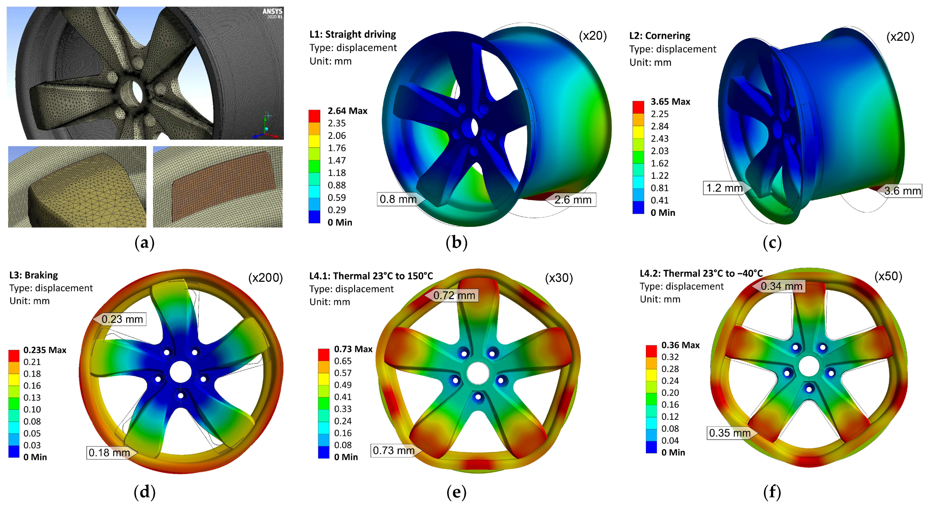
Figure 1. Simulation of the hybrid wheel in different load cases: (a) finite element model of wheel and joint with adhesive layer; (b) wheel displacement during L1: straight driving; (c) displacement during L2: cornering; (d) displacement during L3: braking; (e) displacement during L4.1: thermal load case 23 to 150 °C; (f) displacement during L4.2: thermal load case 23 to −40 °C.
Table 2. Selection of material parameters (for room temperature) used for linear elastic simulation of the hybrid wheel for the analysis of force and moment resultants within the joint.
| Carbon/Epoxy Composite Orthotropic Ply WELA GG-245 [17]/ Araldite® LY 1560 [19] |
Carbon/Epoxy Composite Unidirectional Ply WELA GV-303-0500 [18]/ Araldite® LY 1560 [19] |
Aluminum Alloy, Isotropic EN AW-6082 T6 [16] |
Adhesive, Isotropic BETAMATE™ HTG |
||||||||
|---|---|---|---|---|---|---|---|---|---|---|---|
| Property | Value | Unit | Property | Value | Unit | Property | Value | Unit | Property | Value | Unit |
| Ex | 66.39 1 | GPa | Ex | 124.24 1 | GPa | E | 70.00 3 | GPa | E | 2.54 1 | GPa |
| Ey | 66.39 1 | GPa | Ey | 8.78 1 | GPa | ν | 0.33 3 | - | ν | 0.40 4 | - |
| Gxy | 15.76 1 | GPa | Gxy | 4.70 2 | GPa | α | 23.4 3 | 10−610−6/K | α | 40.0 4 | 10−610−6/K |
| νxy | 0.30 1 | - | νxy | 0.27 2 | - | ||||||
| αx | 2.2 2 | 10−610−6/K | αx | −0.5 2 | 10−610−6/K | ||||||
| αy | 2.2 2 | 10−610−6/K | αy | 30.0 2 | 10−610−6/K | ||||||
1 data determined in coupon tests by Fraunhofer LBF. 2 data from similar material within Ansys Workbench 2020 R1 data base. 3 data from product data sheet [16]. 4 data according to DuPont Specialty Products GmbH & Co KG (Macquarie Park, Australia).
2.3.2. Wheel Deformation in Different Load Cases
For the interpretation of the structural behavior of the joint, examination of the simulated wheel deformation of the different load cases is helpful, as shown in Figure 1b–f.
The load cases “L1: straight driving” (Figure 1b) and “L2: cornering” (Figure 1c) lead to asymmetrical deformation of the wheel with a maximum deformation of 2.6 mm in L1 and 3.6 mm in L2 on the inboard side of the wheel rim. Deformations greater than 5 mm can result in critical tyer leakage. The outboard side of the wheel is less deformed, due to the stiffness of the aluminum wheel disc. However, especially in the case of “cornering”, the high lateral load leads to maximum deformation of the spoke of 1.2 mm.
The load case “braking” (Figure 1d) is rotationally symmetrical, due to the symmetrical introduction of the torsional moment. Only little deformation of max. 0.23 mm occurs in this load case.
For the thermal load cases, a stress neutral temperature at 23 °C is assumed, without consideration of possible residual stresses from the manufacturing process. The temperature rise in “L4.1: Thermal 23 to 150 °C” (Figure 1e) leads to an expansion of the wheel components. Due to the greater thermal expansion rate of the aluminum alloy compared to the composite material, the wheel disc compresses the wheel rim into a polygon-like shape with a maximum deformation of 0.73 mm. The temperature drop in “L4.2: Thermal 23 to −40 °C” (Figure 1e) leads to a greater contraction of the wheel disc, pulling the wheel rim interfaces toward the center axis. Here, the maximum deformation is 0.35 mm.
2.3.3. Force and Moment Resultants within the Joint
In order to evaluate the critical force and moment resultants within the joint, different spoke positions during the 360° rollover need to be considered. Therefore, each load case is simulated in different orientations of the wheel, allowing for a joint evaluation in 18° increments along the 360° rollover. The force and moment resultants are evaluated at the intersection between the outer surface of the aluminum spoke and the inner surface of the adhesive layer, as shown in Figure 2a. The resultants are orientated in a cylindrical coordinate system with a radial (R), lateral (L) and circumferential (φ) direction. A positive radial force resultant +FR can be interpreted as tensional loading of the adhesive layer, a negative radial force resultant −FR as compression loading.
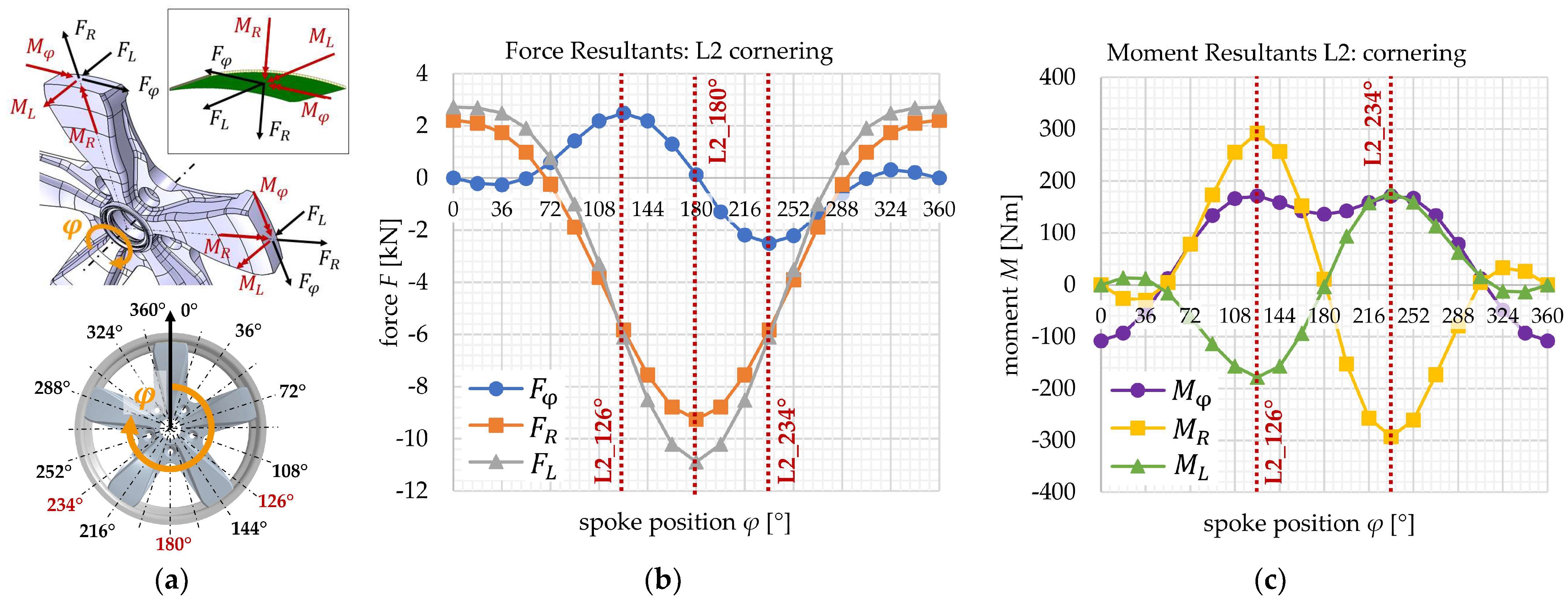
Figure 2. (a) Visualization of force and moment resultants at the intersection between the spoke and the adhesive layer during 360° rollover; (b) force resultants for the load case “L2: cornering”; (c) moment resultants for the load case “L2: cornering”.
An exemplary evaluation of the force and moment resultants over the 360° wheel rollover for the load case “L2: cornering” is shown in Figure 2b,c. The graphical course shows maxima and minima in different spoke positions. Extreme radial and lateral forces occur at 180° spoke position, with extreme circumferential forces as well as all extreme moment resultants at 126° and 234° spoke position.
In Table 3, the selected critical force and moment resultants for each load case are listed, evaluated from the respective extrema in the 360° rollover. In the load case “L1: straight driving”, maximum force resultants within the joint occur at 180° spoke position, with maximum moment resultants at 126° and 234°, similar to the load case “L2: cornering”. However, the load values during cornering appear to be more extreme, with a high radial force resultant of −9.25 kN and a high lateral force resultant of -10.89 kN. The high radial moment resultants of 293 Nm can be explained by to the deformation reaction of the spoke, caused by the circumferential force resultant of 2.50 kN. Due to the open C-shaped cross-section of the spoke, the resulting bending deformation is coupled by a drilling deformation around the radial axis.
Table 3. Selection of critical force and moment resultants within the wheel joint for different load cases and spoke positions.
| No. | Load Case | Spoke Position |
Force Resultants | Moment Resultants | ||||
|---|---|---|---|---|---|---|---|---|
| Fφ | FR | FL | Mφ | MR | ML | |||
| (kN) | (kN) | (kN) | (Nm) | (Nm) | (Nm) | |||
| L1 | straight driving | 126° | 0.87 | −3.67 | −2.84 | 88 | 193 | −205 |
| 180° | 0.08 | −8.39 | −6.64 | 43 | 8 | −5 | ||
| 234° | −0.87 | −3.67 | −2.84 | 88 | −193 | 205 | ||
| L2 | cornering | 126° | 2.50 | −5.83 | −6.10 | 171 | 293 | −178 |
| 180° | 0.13 | −9.25 | −10.89 | 136 | 11 | −3 | ||
| 234° | −2.50 | −5.83 | −6.10 | 171 | −293 | 178 | ||
| L3 | braking | all pos. | −1.52 | 0 | 0 | 0 | −78 | 9 |
| L4.1 | 23 to 150 °C | all pos. | 0 | −28.61 | 0.02 | −67 | 0 | 0 |
| L4.2 | 23 to −40 °C | all pos. | 0 | 14.08 | −0.01 | 33 | 0 | 0 |
The same effect can be observed in the load case “L3: braking”. The braking torque leads to a circumferential force resultant of −1.52 kN within the joint, which then results in a radial moment resultant of −78 Nm, due to the spokes’ cross-sectional design. However, the braking load condition appears to be less critical for the joint, with significantly lower load values compared to the other load cases.
The thermal load cases lead to high residual radial force resultants, as described before. The temperature rise in “L4.1: Thermal 23 to 150 °C” leads to radial force resultants of −28.61 kN, and the temperature drop in “L4.2: Thermal 23 to −40 °C” of +14.08 kN shows far more extreme values than in the other load cases.
When developing the adhesive joint for the hybrid wheel, all force and moment resultants and their interactions need to be considered as structural requirements. The resulting stress state within the adhesive layer depends on the final chosen geometrical design of the joint area. However, the evaluation of the principal stresses of the adhesive layer of this preliminary “basic design” give first conclusions about the joint loading:
-
The high radial force resultant of +14.08 kN in L4.2 leads to critical tensional loading of the joint, due to the significantly lower tensional strength compared to the compressional strength of the adhesive.
-
The high lateral force resultant of −10.89 kN in L2 leads to critical shear loading.
-
The circumferential and lateral moment resultants Mφ and ML can be considered more critical than the radial moment resultant MR, because they lead to out-of-plane pealing stresses rather than in-plane shear stresses within the adhesive layer.
-
The braking/accelerating load case can be considered as the least critical load case, resulting in rather low stress states.
2.4. Joint Design
For the development of the adhesive joint design, several concepts considering the review of literature are generated, analyzed via finite element simulation and evaluated according to their estimated structural performance, reliability, manufacturability and lightweight potential. The concepts include different approaches regarding design parameters such as geometrical design, material selection, bonding direction, as well as adaptations of the rim and spoke design. The final selected design features two main characteristics, which are elaborated in the following:
-
the adaption of the fiber layup in the composite rim flange;
-
the geometrical joint design with a form-fitted radial and lateral support.
2.4.1. Adaption of the Fiber Layup for the Composite Rim
The analysis of the joint requirements shows that critical radial force resultants occur in the thermal load cases due to the different thermal expansion rates of the aluminum wheel disc and the composite wheel rim. In the case of the composite rim, the thermal expansion rate as well as the rim stiffness result from the fiber layup and therefore offer the potential of more convenient design adaptations. In the original rim design (Figure 3a), unidirectional reinforcements are inserted in the rim flange areas with the objective of increasing the rim stiffness in the circumferential direction, as well as realizing thicker areas with a specific surface geometry. However, the reinforcements are primarily necessary for the in-board flange side. On the out-board side, the aluminum wheel disc increases the rim stiffness. This allows for the replacement of the unidirectional reinforcements with foam core segments (Figure 3b), while still achieving sufficient strength and stiffness of the rim flange. This sandwich design leads to a more flexible behavior of the rim flange in circumferential directing, as well as to a reduction of the difference in thermal expansion between the composite and aluminum components.
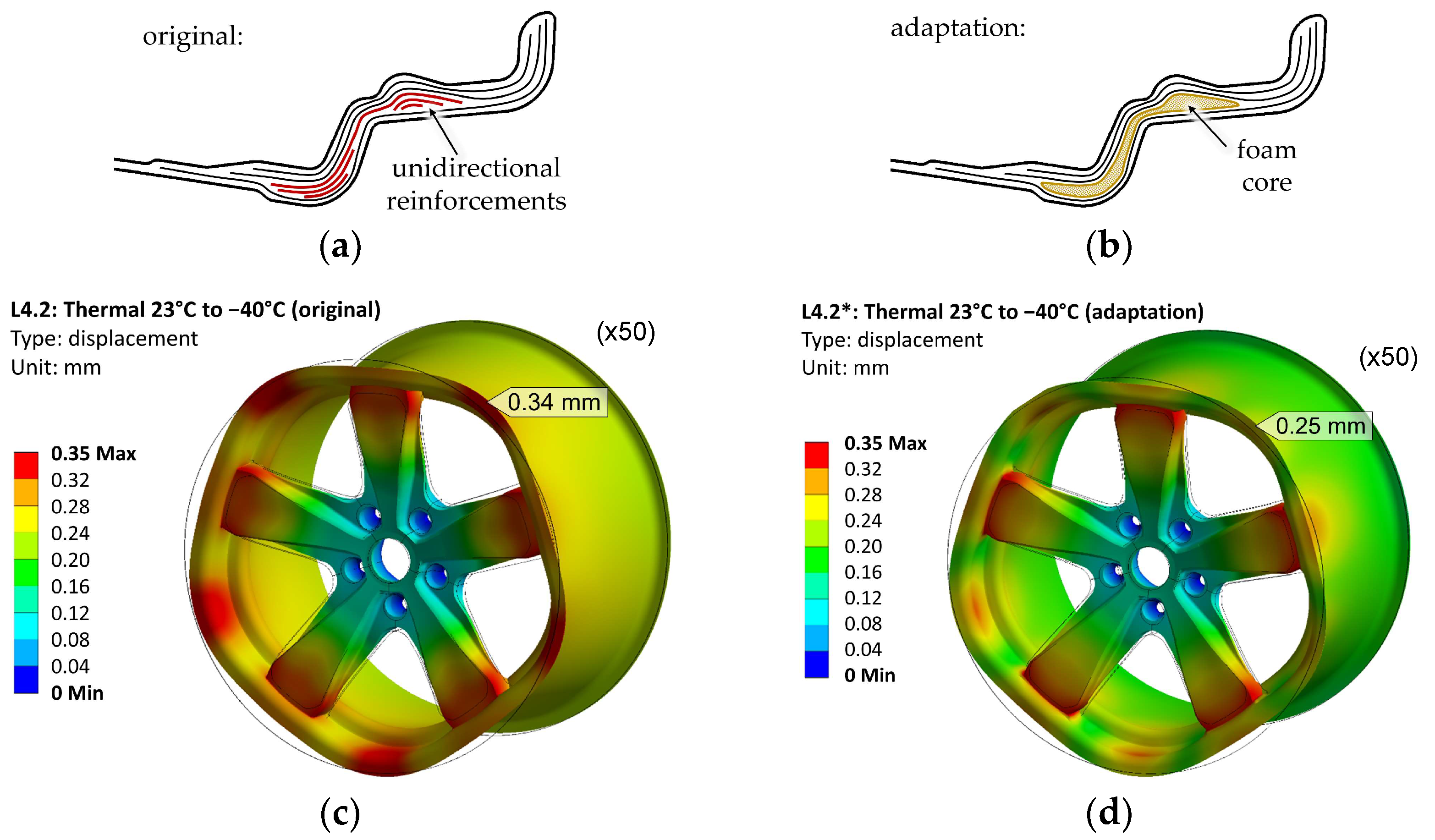
Figure 3. (a) Sketch (no detailed design) of the original fiber layup of the out-board rim flange with unidirectional reinforcements; (b) sketch of the adapted fiber layup with foam core; (c) deformation plot of original design under thermal load 23 to −40 °C; (d) deformation plot of adapted design.
Figure 3c,d show the changes in deformation behavior between the original and the adapted design for the load case “L4.2: Thermal 23 to −40 °C”. In both variations, the shrinkage of the aluminum disc due to the temperature drop is similar. The deviation of the composite rim to its undeformed shape, on the other hand, is less pronounced in the adapted variation, with only a 0.25 mm deviation between the spokes, compared to 0.35 mm in the original design.
Table 4 contains the force and moment resultants for the thermal load cases L4.1* and L4.2*, evaluated with the new design adaptation in the rim flange. The evaluation shows a significant reduction of the radial force resultants by 47%, with −15.18 kN instead of the former −28.61 kN in L4.1, and 7.47 kN instead of the former 14.08 kN in L4.2. Therefore, the design adaptation significantly improves the load requirement for the joint design.
Table 4. Force and moment resultants within the wheel joint for the thermal load cases, evaluated with the design adaptation in the rim flange.
| No. | Load Case | Spoke Position |
Force Resultants | Moment Resultants | ||||
|---|---|---|---|---|---|---|---|---|
| Fφ | FR | FL | Mφ | MR | ML | |||
| (kN) | (kN) | (kN) | (Nm) | (Nm) | (Nm) | |||
| L4.1 * | 23 °C to 150 °C | all pos. | 0 | −15.18 | −0.10 | 53 | 0 | 0 |
| L4.2 * | 23 °C to −40 °C | all pos. | 0 | 7.47 | 0.05 | 26 | 0 | 0 |
* Evaluated from model with design adaptation in the out-board rim flange.
Further investigation of the other load cases “L1*: straight driving”, “L2*: cornering”, and “L3*: braking” with the new design adaptation shows no significant change in force and moment resultants. This can be explained due to the rather force-controlled loading in these load cases, instead of the rather deformation-controlled loading in the thermal load cases.
2.4.2. Geometrical Joint Design
As a critical structural component, the hybrid wheel has high requirements regarding safety and reliability. In the case of adhesive joints, the combination of an adhesive bond with a form-fitted design can improve the joint performance and reduce critical tensional or pealing stresses, as well as enable a fail-safe mechanism in case of adhesive failure. However, the realization of a form-fitted adhesive design requires consideration of the bonding process, e.g., the application of the adhesive and the bonding direction.
Within an iterative design process, considering structural finite element analyses and manufacturing limits, a geometrical joint design is developed, in which a form-fitted radial and lateral support is implemented, as shown in Figure 4. The design is realized by adaptation of the foam core segments in the rim flange in the joint areas. The cross-sectional view shows the “claw-like” fit of the joint, supporting the adhesive bond regarding critical radial and lateral force resultants FR and FL, as well as radial and lateral moment resultants MR and ML. The overall design of the adhesively joined wheel offers a lightweight potential of 6% compared to the bolted hybrid wheel.
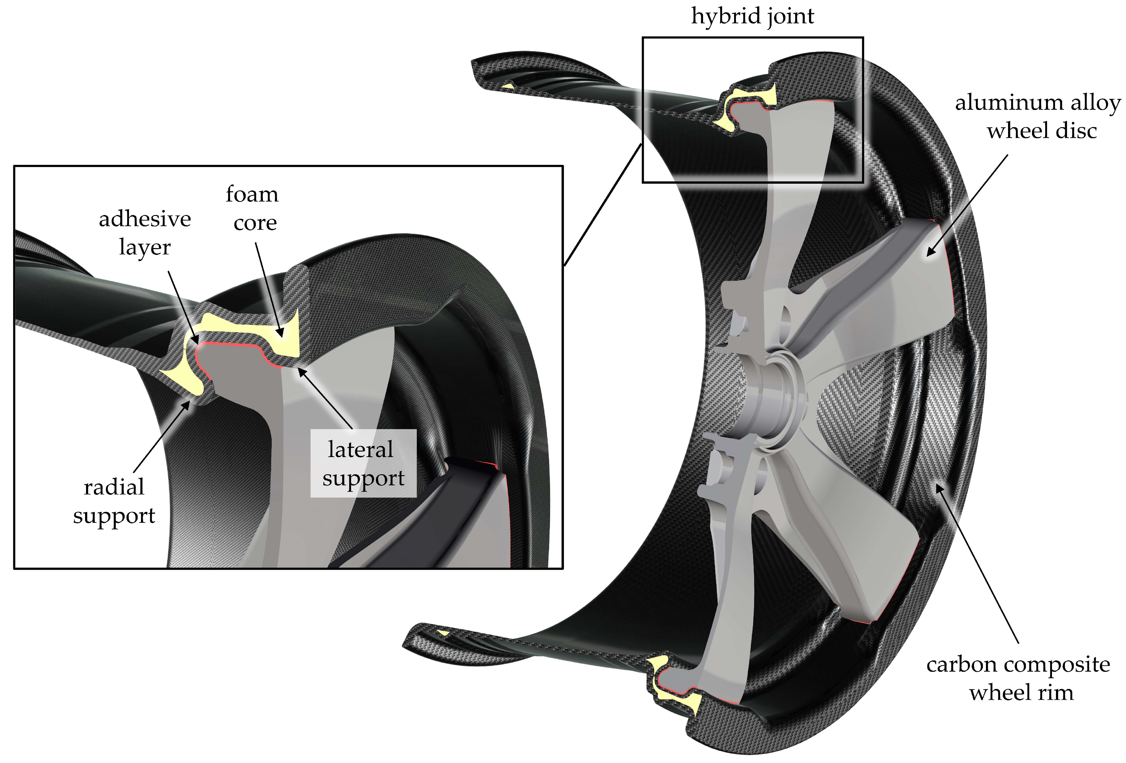
Figure 4. Form-fitted adhesive joint for the hybrid wheel, containing a radial and lateral support.
2.4.3. Manufacturing Concept
The least critical force resultants occur in the circumferential direction (Table 3 and Table 4). Therefore, this degree of freedom is chosen as the bonding direction in which the adhesive bond without a form-fitted lock is considered sufficient. In the developed assembling process, the aluminum wheel disc is fixed on a rotation axis. The disc part is first positioned in between the joint areas of the composite rim. After application of the adhesive, the aluminum disc is rotationally moved into its final position, creating the form-fitted adhesive bond, as visualized in Figure 5a. In order to assure sufficient distribution of the adhesive over the bonding area and the realization of a defined adhesive thickness, the joint is designed in a wedge shape, as shown in Figure 5b. When locking the aluminum disc into position, an out-of-plane contact pressure is inserted, generating an evenly distributed adhesive layer with a constant thickness.
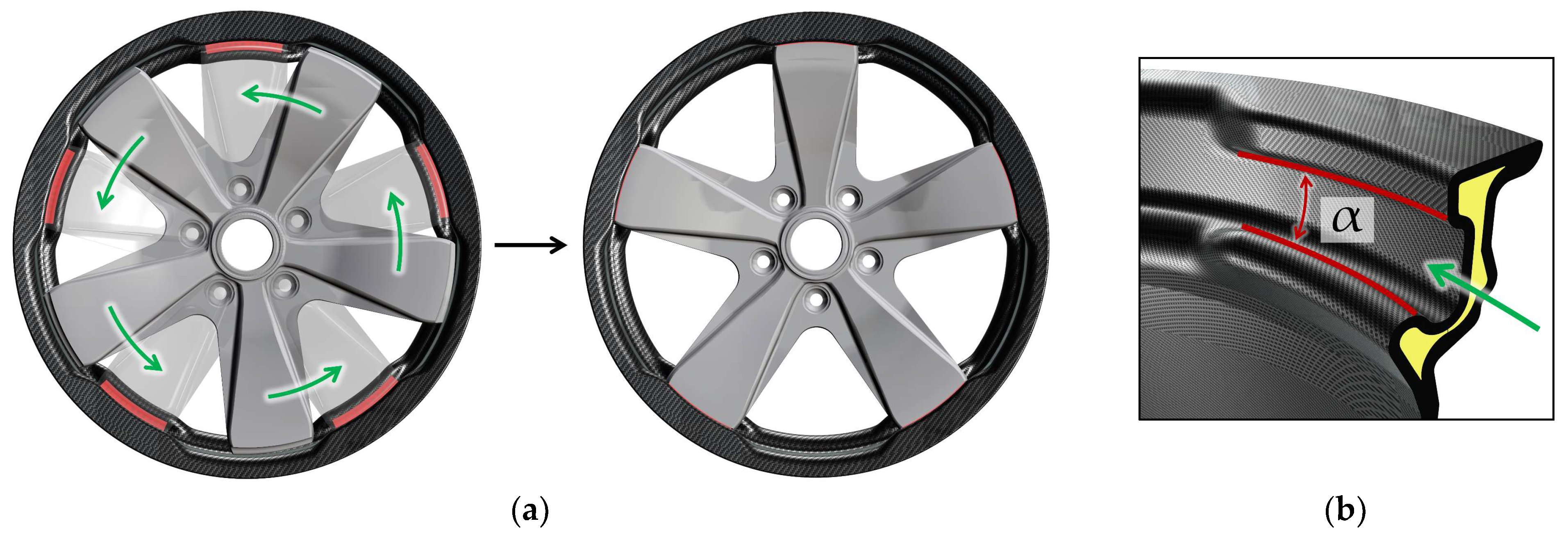
Figure 5. (a) Visualization of the bonding process in rotational direction (green arrow); (b) wedge shape (α) of the joint intersection.
The wedge shape of the joint also enables the manufacturing of the composite rim via resin transfer molding (RTM). The geometry in the joint area can be realized in a multi-part tool, in which the respective tool segment can be demounted in a rotational direction.
References
- Hybrid Composite Wheel Reduces Fuel Consumption. Available online: https://www.reinforcedplastics.com/content/products/hybrid-composite-wheel-reduces-fuel-consumption/ (accessed on 4 January 2023).
- Every Gram Counts-M Carbon Compound Wheels for the BMW M4 GTS. Available online: https://www.bmw-m.com/en/topics/magazine-article-pool/every-gram-counts.html (accessed on 4 January 2023).
- Wheels from the Highest Standard-Mubea Performance Wheels. Available online: https://www.mubea.com/en/mubea-performance-wheels (accessed on 4 January 2023).
- CFK-Räder Gehen 2016 in Serie. Available online: https://www.kfz-betrieb.vogel.de/cfk-raeder-gehen-2016-in-serie-a-505562/ (accessed on 4 January 2023).
- Porsche and the Braided Carbon Fiber Wheel. Available online: https://www.compositesworld.com/articles/porsche-and-the-braided-carbon-fiber-wheel (accessed on 4 January 2023).
- Rondina, F.; Taddia, S.; Mazzocchetti, L.; Donati, L.; Minak, G.; Rosenberg, P.; Bedeschi, A.; Dolcini, E. Development of full carbon wheels for sport cars with high-volume technology. Compos. Struct. 2018, 192, 368–378.
- Wacker, J.-D.; Laveuve, D.; Contell Asins, C.; Büter, A. Design of a composite nose wheel for commercial aircraft. IOP Conf. Ser. Mater. Sci. Eng. 2021, 1024, 012018.
- The Fuchsfelge-Forged, Not Cast. Available online: https://www.fuchsfelge.com/en/the-fuchsfelge.html (accessed on 4 January 2023).
- Thyssenkrupp Carbon Components GmbH. Vehicle Wheel Comprising a Wheel Rim and a Wheel Disc. Patent WO2016/037611A1, 17 March 2016.
- Mubea Carbo Tech GmbH. Wheel for a Vehicle. Patent WO2016/066769A1, 6 May 2016.
- GOHybrid-Gestaltung und Optimierung von Hybridverbindungen unter Besonderer Berücksichtigung der Unterschiedlichen Wärmedehnungen der Werkstoffpartner. Available online: https://www.werkstoffplattform-hymat.de/Group/GOHybrid/Pages (accessed on 4 January 2023).
- Da Silva, L.F.M.; Öchsner, A.; Adams, R.D. Handbook of Adhesion, 2nd ed.; Springer: Berlin/Heidelberg, Germany, 2011; pp. 2–4.
- Marques, E.A.S.; da Silva, L.F.M.; Banea, M.D.; Carbas, R.J.C. Adhesive Joints for Low- and High-Temperature Use: An Overview. J. Adhes. 2015, 7, 556–585.
- Mubea Carbo Tech GmbH. Heat Shield Structure for a Wheel. Patent WO2016/097159A1, 17 March 2016.
- Carbon Revolution PTY Ltd. Method of Producing Thermally Protected Composite. Patent WO2016/168899A1, 27 October 2016.
- OTTO FUCHS KG. EN AW-6082 nach DIN EN 573 FUCHS AS15/AS11. Product Data Sheet, Rev. 1. Available online: https://www.otto-fuchs.com/fileadmin/user_upload/Infocenter/Werkstoffinformationen/Al-Datenblaetter/AS10-15.pdf (accessed on 4 January 2023).
- WELA Handelsgesellschaft mbH. Kohlefasergewebe WELA GG-245-1000T (AKSA A-38). Product Data Sheet. 2020. Available online: https://wela-hamburg.de/wp-content/uploads/2019/01/datenblatt.pdf (accessed on 4 January 2023).
- WELA Handelsgesellschaft mbH. UD-Kohlefasergewebe WELA GV-303-0500UTFX. Product Data Sheet. 2013. Available online: https://wela-hamburg.de/faserverstaerkungen/ (accessed on 4 January 2023).
- Huntsman Advanced Materials. Araldite® LY 1560/Aradur® 917-1/Accelerator DY 079. Product Data Sheet. 2016. Available online: https://www.huntsman-transportation.com/EN/products/all-products/composite-resin-systems.html/ (accessed on 4 January 2023).
More
Information
Subjects:
Transportation Science & Technology
Contributors
MDPI registered users' name will be linked to their SciProfiles pages. To register with us, please refer to https://encyclopedia.pub/register
:
View Times:
1.2K
Revisions:
2 times
(View History)
Update Date:
23 Mar 2023
Table of Contents


Notice
You are not a member of the advisory board for this topic. If you want to update advisory board member profile, please contact office@encyclopedia.pub.
OK
Confirm
Only members of the Encyclopedia advisory board for this topic are allowed to note entries. Would you like to become an advisory board member of the Encyclopedia?
Yes
No
${ textCharacter }/${ maxCharacter }
Submit
Cancel
Back
Comments
${ item }
|
${ item.createdUser.fullName }
${ item.createdAt }
${ item.vote }
${ item.reply }
Delete
${ reply.createdUser.fullName }
${ reply.createdAt }
${ reply.vote }
Delete
There is no reply to this comment~
${ item.replyTextCharacter }/${ item.replyMaxCharacter }
Submit
Cancel
More
No more~
There is no comment~
${ textCharacter }/${ maxCharacter }
Submit
Cancel
${ selectedItem.replyTextCharacter }/${ selectedItem.replyMaxCharacter }
Submit
Cancel
Confirm
Are you sure to Delete?
Yes
No