Raouf, A.; Tawfiq, K.B.; Eldin, E.T.; Youssef, H.; El-Kholy, E.E. Wind Energy Conversion Systems Based on Synchronous Generator. Encyclopedia. Available online: https://encyclopedia.pub/entry/42423 (accessed on 24 July 2026).
Raouf A, Tawfiq KB, Eldin ET, Youssef H, El-Kholy EE. Wind Energy Conversion Systems Based on Synchronous Generator. Encyclopedia. Available at: https://encyclopedia.pub/entry/42423. Accessed July 24, 2026.
Raouf, Amir, Kotb B. Tawfiq, Elsayed Tag Eldin, Hossam Youssef, Elwy E. El-Kholy. "Wind Energy Conversion Systems Based on Synchronous Generator" Encyclopedia, https://encyclopedia.pub/entry/42423 (accessed July 24, 2026).
Raouf, A., Tawfiq, K.B., Eldin, E.T., Youssef, H., & El-Kholy, E.E. (2023, March 22). Wind Energy Conversion Systems Based on Synchronous Generator. In Encyclopedia. https://encyclopedia.pub/entry/42423
Raouf, Amir, et al. "Wind Energy Conversion Systems Based on Synchronous Generator." Encyclopedia. Web. 22 March, 2023.
Copy Citation
Wind Energy Conversion Systems Based on Synchronous Generator
Since 20th century, electricity has been widely available, and a large portion of it is produced using coal and gas. Because of its adaptability and simplicity of delivery, electricity is a premium kind of energy. Global demand is rising because of rising consumer electronics, associated industrial activities, and greater consumer access in emerging nations. The most reliable and progressive renewable energy source is wind power. Utilizing the highest amount of wind power available and operating the wind turbine (WT) at its maximum energy conversion output is essential for the rapid adoption of wind generators in electrical grids. To complete this, a wind energy conversion system (WECS) must track or run at the maximum power point.
wind turbine (WT)maximum power point tracking (MPPT)optimal torque control (OTC)power signal feedback (PSF)tip speed ratio (TSR)
1. Wind Energy
Wind energy is one of the fastest-growing approaches to producing electrical power in the world. Wind power or wind energy is the process of using the wind to produce mechanical or electrical power. Wind energy has been utilized for at least 3000 years [1][2]. Up to the 20th century, wind energy was employed to generate mechanical power for tasks such as water pumping or grinding grain applications [1][2]. At the outset of modern industrialization, the use of erratic wind energy supply has been superseded using fossil fuel-fired engines or electrical grids, which are considered a reliable power source. Therefore, the usage of wind energy is separated into two categories: (1) the generation of mechanical power and (2) the generation of electrical power.
Wind is simple air in motion, and it is caused by the uneven heating of the earth’s surface by the sun. The sun’s heat is absorbed by the earth’s surface at varying rates since the land and water types are so diverse. The air above land warms up during the daytime quicker than the air above the sea. The heavier and cooler air rushes in to replace the expanding and rising warm air over the ground, causing winds. Because the air cools quicker over land than it does over water at night, the winds are inverted. Similar to how the area around the equator is scorched by the sun more than the land near the North and South Poles, the huge air winds that circle the world are generated.
1.1. Wind Energy Equation
Environmental conditions can influence the available wind energy in a location. However, wind turbine design aspects also play a key role in the energy capacity of the turbine. The amount of energy produced by a turbine is given as follows [3]:
Environmental conditions, such as air density, ρ, and wind velocity, U, are uncontrollable parameters of nature. Air density changes with elevation, temperature, and humidity. The speed, direction, and intensity of the wind are functions of the site location [4]. Design parameters such as the swept area, A, and coefficient of performance,cp, influence the energy capacity of the turbine and can be maximized with proper design [5].
1.2. Classification of Wind Turbine Rotors
According to how the axis of rotation faces the direction of the wind, wind turbines are often divided into two groups [6][7][8][9]:
Vertical-axis turbines;
Horizontal-axis turbines.
1.2.1. Vertical-Axis Wind Turbines
The vertical-axis framework served as the foundation for the earliest windmills. Only small-scale installations of this kind have used it. The Darrius rotor, is a common component of vertical-axis wind turbines (VAWTs) [6][7]. Rotor shafts in VAWTs are placed vertically. It is not necessary for the vertical shaft that the blades revolve around to face the wind to be vertical. The advantage of a vertical axis rotating shaft is that the generator and electrical components may be positioned close to the ground. The blades of a VAWT are subject to turbulence and drag forces. Because it is difficult to put vertical blades on a tall tower, the turbine must be located close to the ground. This causes the turbine to be influenced by sluggish wind and greater turbulence, which causes vibration and requires more maintenance [8][9].
1.2.2. Horizontal-Axis Wind Turbines
The most widespread form of a wind turbine is horizontal axis wind turbine (HAWT). The structure of a HAWT is modeled after windmills, which feature blades that revolve and spin along a horizontal axis [6][7]. The rotor shaft, which is regarded as the shaft of the electrical generator, is primarily the horizontal axis. When the wind turbine is modest in size. The horizontal shaft is linked to the generator shaft directly; however, when the wind turbine is large, it is connected via a gearbox. The gearbox serves to improve the speed while reducing stress and vibration. It is situated between moderate and fast rotational speeds. VAWTs can face upwind or face downwind [8][9]. Since mounting and pointing the blades upwind would reduce the turbulence impact created by the tower, upwind turbines must be constructed with robust blades to resist bending by high winds toward the tower [8]. The blades may be constructed with less stiffness in downwind turbines because they have more room to bend and will not bend toward the tower, which solves the problem of turbulence created by the tower. Most wind turbines are constructed upwind because turbulence stresses the blades and produces fatigue problems [8][9].
1.3. World Wind Energy Scenario
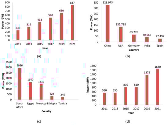
According to records from the Global Wind Energy Council (GWEC), installed wind power increased globally in 2021 to 837 GW, preventing the emission of more than 1.2 billion tons of CO2 annually. With 93.6 GW of the new installed capacity, 2021 is now the second-best year in the history of growth for the global wind industry, trailing only the record-breaking year of 2020, which was 1.8% higher. The top producers globally are China, the United States of America, Germany, India, and Spain [10]. The global wind power output for the last ten years in 2021 is shown in Figure 1a. Figure 1b shows the wind energy output for the top five countries in the globe in 2021. With 328,973 GW, China produces the most wind energy worldwide. With 132,738 GW, the United States ranks in second place in the world and first place in North America for wind energy. With 63,776 GW, Germany has the biggest capacity in Europe. Figure 1c shows the top five African countries in terms of wind energy production in 2021. With 2956 MW, South Africa has the most wind power generation in Africa. Morocco comes in third place with a production of around 1435 MW, while Egypt is in second place with over 1640 MW. In Egypt, the production of electrical power from wind energy began in 2011 with 550 MW and expanded progressively, as seen in Figure 1d, to reach 1640 MW in 2021 [11]. The GWEC anticipates a sharp increase in new installations through 2026 (+6.6%/year), with annual onshore wind installations rising from 72.5 GW in 2021 to 97.4 GW in 2026. Annual offshore wind capacity additions should also pick up from 21.1 GW in 2021 to 31.4 GW in 2026. In total, wind capacity additions should surpass 100 GW/year as of 2022, reaching 128.8 GW in 2026. In terms of capacity increase, China should continue to dominate installations (41% in 2026) followed by Europe (14% in 2026) and North America (7% in 2026) [12].
Figure 1. Wind energy trend in the world and in Africa and Egypt: (a) wind energy trend in the world; (b) top five wind power production in the world in 2021; (c) top five wind power production in Africa in 2021; (d) wind energy trend in Egypt.
2. Block Diagram of a Typical Grid-Connected WECS
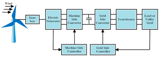
In WECSs, a wind turbine and an electric generator are used to produce electrical energy from the wind. The prime mover and the wind turbine can be connected directly or through a gearbox configuration. The rotor of the generator is where the prime mover is connected, and the stator is where the utility grid or separate loads are connected via an appropriate power electronic interface. For the utility grid, this system transforms mechanical energy into magnetic energy and then electrical energy. Figure 2 depicts the block diagram of a typical grid-connected WECS. Depending on their unique operating characteristics at various wind speeds, wind turbines are divided into two groups: variable speed wind turbines (VSWT) and fixed speed wind turbines (FSWT). The generator in FSWTs is directly plugged into the grid. The energy produced by the wind is subject to unpredictable fluctuations until the rotor speed catches up with the grid frequency. The grid’s power quality is significantly impacted by these variations. Power electronics can regulate the generator and rotor speed in VSWT. By adjusting the rotor speed with this control, wind-related power variations can be reduced [13][14][15].
Figure 2. Block diagram of a typical grid-connected WECS.
3. Power Control Techniques in Wind Turbines
WTs are normally made to tolerate severe weather, but they are not made to handle high rotating speeds or torques. The force acting on the WT’s blades is massive and has the potential to destroy the turbine at very high aerodynamic torques or rotational speeds. WTs are always built with a cut-out speed below which brakes will bring the turbine to a stop and prevent this destruction from happening. The WT uses a variety of control mechanisms to deal with high wind speeds that might otherwise endanger the turbines during a range of wind speeds before the cut-out speed. As a result, all WTs are created with some sort of power control method. Stall control or pitch control are the two options here. Passive and active stall control are additional categories for WT stall management.
3.1. Stall Control
The primary benefit of stall control is the avoidance of complicated control systems and moving elements in the rotor itself. On the other side, stall management poses extremely challenging design difficulties in both aerodynamics and the structural dynamics of the entire wind turbine, such as how to prevent stall-induced vibrations. Stall-controlled devices are used in almost two-thirds of the wind turbines that are now installed in the world.
To limit the power in very high wind speeds and prevent wind turbine damage, there are many approaches to managing aerodynamic forces on the turbine’s rotor. As a result, WECSs are divided into three types by the input wind power control ability: passive stall, active stall, and pitch control [16][17][18][19].
3.1.1. Passive Stall Power Control
Blades on passively stalled controlled WTs are fixedly angled when fastened to the hub. To induce turbulence on the side of the rotor blade that is not facing the wind, the geometry of the rotor blade profile is aerodynamically optimized. This stall stops the rotor from being lifted by the rotor blade’s lifting force. When the wind speed approaches its critical value, the rotor blade of a passively stalled controlled WT is gradually twisted along its longitudinal axis to guarantee a progressive stalling rather than a sudden one. This is a straightforward and inexpensive technology that does not need the installation of extra actuators, but since it relies so heavily on the natural stalling of the turbine blades, the controllability of the WT is severely constrained. With passive stall management, the output power of the WT marginally exceeds the rated limit before falling until it approaches the cut-out speed. By acting in this way, the wind generator is protected from overloading when the wind speed exceeds the nominal values. With no complexity related to WT control or the moving elements of the WT rotor, the passive stall control of WTs offers a relatively straightforward control scheme. Under fixed-speed WT systems, passive stall control is used to ensure that the WT’s rated power is not exceeded in high wind conditions. Because of the limited activities, this usually results in poor power control [17][18][19].
3.1.2. Active stall Power Control
The active stall power control of WTs was devised in reaction to what seemed to be a failure of the passive stall control. Similar to pitch-controlled WTs, active stall-controlled WTs include patchable blades and active power control devices. Although it may also be used with fixed-speed WTs created to operate in high-speed wind situations, active stall management of WTs is common with bigger WTs rated at 1 MW and beyond. The WT blades are pitched in stages when there is little wind to provide a powerful torque. The WT generator must not be overloaded at its rated power; therefore, instead of reducing the angle of attack to decrease the lift and rotational speed of the rotor blades, the active stall-controlled WT increases the angle of attack to cause the blades to enter a deeper stall. Active stall control, as opposed to passive stall control, offers more precise power output management to prevent exceeding the WT’s rated power at the start of a wind gust. Running the WT nearly at rated power at all high wind speeds is another benefit of active stall control over passive stall control. For increasing wind speeds, a passive stall-controlled WT typically experiences a decrease in electrical power production as the rotor blades enter a deeper stall [17][18][19].
3.2. Pitch Control
Pitch-regulated WTs uses an electronic controller to continuously measure the output power of the WT. An electrical signal is generated when the power level exceeds the advised safe limit, which forces the turbine blades to tilt away from the wind. The turbine blades are pitched or turned back toward the wind at the highest angle of attack to collect the wind when the power level declines. By pitching the WT blades, minimal power loss may be accomplished, resulting in the collected power being equivalent to the electrical power generated by the wind generator. To reduce the torque and rotational speed in WTs, pitch-regulated WTs use an active control system that changes the pitch angle of the turbine blades. This type of control is normally employed only when high rotational speeds and aerodynamic torques might destroy the equipment.
Strong wind conditions make the distinctions between the pitch control and stall control of WTs clear. In contrast to stall-controlled systems, pitch-controlled systems actively adjust the pitch of the blades. As a result, the pitch-controlled system can maintain a steady power output above the specified wind speed, but the stall-controlled systems cannot do so in strong winds. WTs’ active stall control and pitch control both depend on the spinning movements of the WT blade. The rotation of the WT blades distinguishes the two modes of operation. In contrast to pitch control, which spins the blade away from the wind to minimize lift force on the turbine blades, active stall control of the WT moves the turbine blades into the wind. Individual pitch control (IPC) and collective pitch control (CPC) are the two control methods used for pitch control of WTs.
4. Characteristic Power Curve-Based MPPT
Most wind energy control systems are based on the monitoring of wind speed. Anemometers are often used in these systems to measure wind speed. Such systems are complicated and have higher sensor costs. Wind speed estimate techniques have been described as a solution to this issue. The wind speed may be measured and used to regulate the ideal tip–speed ratio so that the MPPT can be used. This is conducted by using sophisticated software algorithms. Additionally, directly monitoring the output power might be used to track the maximum power. To obtain the most power out of the wind turbine system, this approach involves measuring the output power in real-time and examining the rate at which power changes with speed, (dP/dω) [20]. By altering the converter’s rotor speed or duty cycle, MPPT may be obtained when dP/dω = 0. Since this approach is heavily reliant on online computing, it would be challenging to accomplish MPPT for rapidly fluctuating wind speeds. Even though the variable tracking step might be utilized to speed up the calculation, this drawback cannot be overcome [20]. Due to its ease of usage in both hardware and software, a recently developed approach of using the power versus rotor speed characteristic curve is widely employed. The best reference power curve is created based on trial results and written into the memory of a microcontroller, acting as a lookup table to control power, one could either measure the wind speed and receive the power reference (Popt), or one could measure the rotor speed (ωm) and obtain the power reference. While the latter will have a quicker control response, the former delivers more precise output power. In addition to a precise reference power curve, analysis is required to confirm the method’s stability under a range of output power and wind speeds. Few papers just discuss the method’s stability problem, but a more thorough quantitative study must be conducted [20].
5. MPPT in Wind
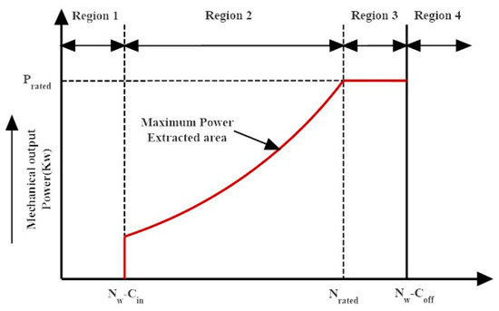
Figure 3 depicts the typical power–speed characteristic of a wind turbine. There are four separate operating areas based on wind speed. Because a reliable power output cannot be anticipated before the cut-in (Cin) and after the cut-off (Coff) speeds, Regions 1 and 4 are not possible, and it is not advised to operate wind turbines during these times for grid connection. The best zone for power production with WECS is now the second region between NW − Cin, and Nrated. Furthermore, only once the wind turbine runs in this area, a maximum power point operating point is achieved. The control of the mechanical output power is necessary because, in the third region (Nrated − NW − Coff), the turbine has already achieved its maximum power limit. The abovementioned discussion implies that Area 2 is the best place to apply WECS maximum power point tracking [21][22][23].
Figure 3. Different operating regions of wind turbines are based on wind velocity.
The MPPT techniques, as previously noted, may be divided into IPC and DPC groups. Additionally, various cutting-edge MPPT approaches based on artificial intelligence are taken into consideration. IPC control systems use the tip speed ratio (TSR), optimum torque (OT), and power signal feedback (PSF) techniques in the context of MPPT techniques. On the other hand, the P and O, incremental conductance (INC), and optimal relation-based (ORB) MPPT techniques are used to accomplish the pre-established optimum relationship.
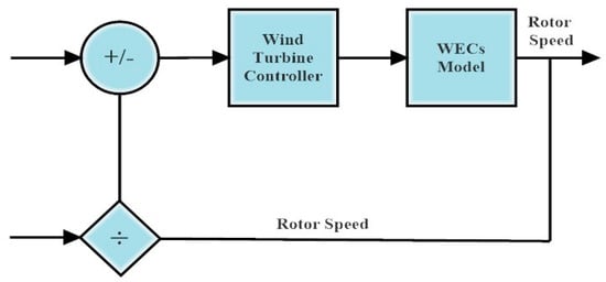
5.1. Optimal Torque Control (OTC)-Based MPPT Technique
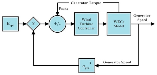
Figure 4 illustrates the OTC technique. The fundamental idea of this technique is to change the generator’s torque from the target wind turbine speed (WTS) to the best energy reference torque. The final speed and the ratio of TS can be used to predict turbine performance. Therefore, the wind speed may be calculated using the best torque equation as follows:
where, ωt,Pt_opt,Ttopt,Cp_opt,andρ are rotor angular speed in rad/s, the optimal output power, optimal torque, optimal power coefficient, and air density, respectively.
Figure 4. OT control method.
Where Equation (3) is an analytical formulation of the OT curve that may be used to adjust mechanical torque. There aren’t many differences in terms of complexity and power between the MPPT controller and the OTC-based MPPT controller. The OT control approach is productive, quick to use, and easy to plan. OTC’s efficiency is lower than TSR because it cannot anticipate WS smoothly [24][25][26].
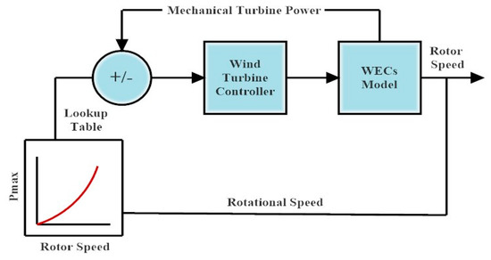
5.2. Power Signal Feedback (PSF)-Based MPPT Technique
PSF technology, which differs from MPPT in many ways, relies on algorithms for power sensor feedback in the absence of power signals. To find the optimal efficiency using this MPPT approach, basic training of optimal curves is necessary. Figure 5 illustrates the basic PSF block diagram. The highest force at a specific wind speed is used as the reference force in the PSF technique. Due to the need for previous knowledge of WT characteristics and wind speed data, this has led to issues [24][25][26].
Figure 5. Basic block diagram of PSF.
5.3. Tip Speed Ratio (TSR)-Based MPPT Technique
The MPPT approach based on tip speed ratio (TSR) is simple since experimentally anticipated straight and continuous wind movement may be considered. Independent of wind speed, the optimal TSR for a given WT is found. As shown in Figure 6, the wind speed is measured to obtain the ideal rotor speed above the ideal end speed level. Using the power and speed of the WT to estimate the approximate wind speed, the prediction approach is based on the auxiliary vector’s repulsion.
Figure 6. Basic block illustration of TSR.
With its rapid reaction and excellent efficacy, TSR control recommends the highest efficiency. There is no way to quantify the actual wind speed. The price of the system increases due to the high cost of the ideal anemometer.
The inverted U-shaped graph between the power and rotor speed is used by the HCS technique of MPPT. The technique compares the current power at a given instant to the power gained at the previous step since there is a certain peak power that corresponds to a given rotor speed. To obtain the operating point closer to the peak power, the duty cycle of the gating pulse supplied to the converter switches is raised if it is discovered that the power is rising. The duty cycle is decreased if it is discovered that the power is dropping. This method’s simplicity and independence from wind turbine parameters are its main advantages. The HCS technique’s serious drawback is its inability to follow the greatest power point in situations with drastically changing wind conditions. The increments and decrements delivered to the duty cycle in conventional HCS approaches are fixed [27][28].
5.5. Perturbation and Observation (P and O)-Based MPPT Technique
The mathematical optimization approach called perturbation and observation (P and O) or hill climb searching (HCS) is used to look for the local maximum points of a given function. It is frequently used in wind energy systems to determine the ideal operating position that optimizes the energy collected. This approach is based on changing a control parameter in tiny steps and monitoring how the target function changes as a result all the way up to the point where the slope is zero. if the operating point is to the left of the peak point, the controller must change the operating point to the right to be closer to the MPPT and vice versa if it is to the right. While studying the mechanical force, some authors adjust the speed of the spin. Others keep an eye on the generator’s electrical output power while altering the inverter’s input voltage or another converter variable, such as the duty cycle, d, input current, Iin, or input voltage, Vin. Mechanical sensors are more dependable and less expensive since they are not needed in approaches that employ electrical power measurement.
The P and O approach is independent, straightforward, and adaptable since it does not require prior knowledge of the characteristic curve of a wind turbine. If it is utilized for big and medium inertia wind turbines, it does not, however, attain the maximum power points with fast wind fluctuations. Additionally, selecting the right step size is a difficult issue since a bigger step size results in a faster reaction time but less efficiency, whereas a smaller step size increases efficiency but slows down convergence speed [29][30][31][32].
The INC technique’s independence from sensor specifications and wind turbine and generator technical requirements lowers system costs and boosts system dependability. This technique also excels at handling nonlinearity, responding dynamically, and is simple to use. The operational point of the MPPT may be identified using the power–speed slope according to the authors. If the slope is positive, the operating point is said to be on the right side of the speed–power characteristics, and if the slope is negative, the opposite is true.
References
Ali, M.H. Wind Energy Systems: Solutions for Power Quality and Stabilization; CRC Press: Boca Raton, FL, USA, 2012.
Ackermann, T.; Söder, L. Wind energy technology and current status: A review. Renew. Sustain. Energy Rev. 2000, 4, 315–374.
Tawfiq, K.B.; Mansour, A.S.; Ibrahim, M.N.; El-Kholy, E.E.; Sergeant, P. Implementation of Matrix Converter in Wind Energy Conversion System with Modified Control Techniques. Electric Power Components and Systems 2019, 47, 1316–1331.
Moran, M.J.; Shapiro, H.N.; Boettner, D.D.; Bailey, M.B. Fundamentals of Engineering Thermodynamics; John Wiley & Sons: Hoboken, NJ, USA, 2010.
Liljestrom, K.W. Integrating Horizontal and Vertical Axis Wind Turbines for a Point Conversion. Ph.D. Thesis, San Diego State University, San Diego, CA, USA, 2016.
Zobaa, A.F.; Bansal, R.C. (Eds.) Handbook of Renewable Energy Technology; World Scientific: Singapore, 2011.
Rao, K.R. Wind Energy for Power Generation: Meeting the Challenge of Practical Implementation; Springer Nature: Berlin/Heidelberg, Germany, 2019.
Yousef, A.; Nasiri, A.; Abdelbaqi, O. Wind turbine level energy storage for low voltage ride through (LVRT) support. In Proceedings of the 2014 IEEE Symposium on Power Electronics and Machines for Wind and Water Applications, Milwaukee, WI, USA, 24–26 July 2014.
El-Sharkawi, M.A. Wind Energy: An Introduction; CRC Press: Boca Raton, FL, USA, 2015.
Available online: https://aeeolica.org/en/about-wind-energy/wind-energy-in-the-world/ (accessed on 1 November 2022).
“Wind Data”. Available online: http://www.thewindpower.net/country_list_en.php (accessed on 1 November 2022).
Available online: https://www.enerdata.net/publications/daily-energy-news/global-wind-capacities-increased-94-gw-2021-837-gw.html (accessed on 1 November 2022).
Kumar, D.; Chatterjee, K. A review of conventional and advanced MPPT algorithms for wind energy systems. Renew. Sustain. Energy Rev. 2016, 55, 957–970.
Bekiroglu, E.; Yazar, M.D. MPPT Control of Grid Connected DFIG at Variable Wind Speed. Energies 2022, 15, 3146.
Zhang, Y.; Zhang, L.; Liu, Y. Implementation of maximum power point tracking based on variable speed forecasting for wind energy systems. Processes 2019, 7, 158.
Deode, D.; Kishore, N. A Review on Performance Analysis of PMSG in Wind Energy Conversion System. Int. J. Eng. Innov. Technol. (IJEIT) 2016, 5, 42–49.
Chaudhuri, A.; Datta, R.; Kumar, M.P.; Davim, J.P.; Pramanik, S. Energy conversion strategies for wind energy system: Electrical, mechanical and material aspects. Materials 2022, 15, 1232.
Hiremath, R.; Moger, T. Comprehensive review on low voltage ride through capability of wind turbine generators. Int. Trans. Electr. Energy Syst. 2020, 30, e12524.
Wagner, H.J.; Mathur, J. Introduction to Wind Energy Systems: Basics, Technology and Operation; Springer: Berlin/Heidelberg, Germany, 2018.
Zou, Y.; Elbuluk, M.; Sozer, Y. Stability analysis of maximum power point tracking (MPPT) method in wind power systems. IEEE Trans. Ind. Appl. 2013, 49, 1129–1136.
Ram, J.P.; Rajasekar, N.; Miyatake, M. Design and overview of maximum power point tracking techniques in wind and solar photovoltaic systems: A review. Renew. Sustain. Energy Rev. 2017, 73, 1138–1159.
Abdullah, M.A.; Yatim, A.H.M.; Tan, C.W.; Saidur, R. A review of maximum power point tracking algorithms for wind energy systems. Renew. Sustain. Energy Rev. 2012, 16, 3220–3227.
Malik, M.Z.; Baloch, M.H.; Gul, M.; Kaloi, G.S.; Chauhdary, S.T.; Memon, A.A. A research on conventional and modern algorithms for maximum power extraction from wind energy conversion system: A review. Environ. Sci. Pollut. Res. 2021, 28, 5020–5035.
Koondhar, M.A.; Ali, M.; Keerio, M.U.; Junejo, A.K.; Laghari, I.A.; Chandio, S. Wind energy conversion system using maximum power point tracking technique—A comprehensive survey. Appl. Eng. Lett. 2021, 6, 148–156.
Hussain, M.; Baloch, M.H.; Memon, A.H.; Pathan, N.K. Maximum power tracking system based on power electronic topology for wind energy conversion system applications. Eng. Technol. Appl. Sci. Res. 2018, 8, 3392–3397.
Pande, J.; Nasikkar, P.; Kotecha, K.; Varadarajan, V. A review of maximum power point tracking algorithms for wind energy conversion systems. J. Mar. Sci. Eng. 2021, 9, 1187.
Badawi, A.; Hasbullah, N.F.; Yusoff, S.H.; Aisha, H.; Zyoud, A. Novel technique for hill climbing search to reach maximum power point tracking. Int. J. Power Electron. Drive Syst. (IJPEDS) 2020, 11, 2019.
Zebraoui, O.; Bouzi, M. Comparative Study of Different MPPT Methods for Wind Energy Conversion System. Int. J. Trend Innov. Res. (IJTIIR) 2021, 3.
Abdullah, M.A.; Yatim, A.H.M.; Tan, C.W. A study of maximum power point tracking algorithms for wind energy system. In Proceedings of the 2011 IEEE Conference on Clean Energy and Technology (CET), Kuala Lumpur, Malaysia, 27–29 June 2011.
Dursun, E.H.; Kulaksiz, A.A. MPPT control of PMSG based small-scale wind energy conversion system connected to DC-bus. Int. J. Emerg. Electr. Power Syst. 2020, 21, 1–13.
Fatah, A.; Benlaloui, I.; Mechnane, F.; Boutabba, T.; Khamari, D.; Drid, S.; Chrifi-Alaoui, L. A Modified Perturbe and Observe MPPT Technique for Standalone Hybrid PV-Wind with Power Management. In Proceedings of the 2021 International Conference on Control. Automation and Diagnosis (ICCAD), Grenoble, France, 3–5 November 2021.
Youssef, A.R.; Mousa, H.H.; Mohamed, E.E. Development of self-adaptive P&O MPPT algorithm for wind generation systems with concentrated search area. Renew. Energy 2020, 154, 875–893.
Contributors
MDPI registered users' name will be linked to their SciProfiles pages. To register with us, please refer to https://encyclopedia.pub/register
:
You are not a member of the advisory board for this topic. If you want to update advisory board member profile, please contact office@encyclopedia.pub.
OK
Confirm
Only members of the Encyclopedia advisory board for this topic are allowed to note entries. Would you like to become an advisory board member of the Encyclopedia?
 +1 credit