Your browser does not fully support modern features. Please upgrade for a smoother experience.
Submitted Successfully!
 +1 credit
Thank you for your contribution! You can also upload a video entry or images related to this topic.
For video creation, please contact our Academic Video Service.
| Version | Summary | Created by | Modification | Content Size | Created at | Operation |
|---|---|---|---|---|---|---|
| 1 | Mohsin Iqbal | -- | 1498 | 2023-03-03 04:29:52 | | | |
| 2 | Dean Liu | -43 word(s) | 1455 | 2023-03-10 02:24:14 | | | | |
| 3 | Dean Liu | Meta information modification | 1455 | 2023-03-10 06:35:56 | | |
Video Upload Options
We provide professional Academic Video Service to translate complex research into visually appealing presentations. Would you like to try it?
Cite
If you have any further questions, please contact Encyclopedia Editorial Office.
Iqbal, M.; Karuppanan, S.; Perumal, V.; Ovinis, M.; Rasul, A. Rehabilitation of Tubular Joints. Encyclopedia. Available online: https://encyclopedia.pub/entry/41834 (accessed on 28 July 2026).
Iqbal M, Karuppanan S, Perumal V, Ovinis M, Rasul A. Rehabilitation of Tubular Joints. Encyclopedia. Available at: https://encyclopedia.pub/entry/41834. Accessed July 28, 2026.
Iqbal, Mohsin, Saravanan Karuppanan, Veeradasan Perumal, Mark Ovinis, Adnan Rasul. "Rehabilitation of Tubular Joints" Encyclopedia, https://encyclopedia.pub/entry/41834 (accessed July 28, 2026).
Iqbal, M., Karuppanan, S., Perumal, V., Ovinis, M., & Rasul, A. (2023, March 03). Rehabilitation of Tubular Joints. In Encyclopedia. https://encyclopedia.pub/entry/41834
Iqbal, Mohsin, et al. "Rehabilitation of Tubular Joints." Encyclopedia. Web. 03 March, 2023.
Copy Citation
Exposure to load and offshore environment degrades the load-bearing capacity of tubular joints, necessitating reinforcement of these joints. Reinforcement is sometimes required for lifespan enhancement or qualification based on new requirements. Available reinforcement techniques include welded rings inside/outside the chord, doubler/collar plate at the brace-chord interface, grout filling, and clamp installation on the joints with/without cement. While these techniques increase the load-bearing capacity of damaged tubular joints, various practical limitations exist.
tubular joints
joint reinforcement
joint rehabilitation
underwater joint repair
1. Introduction
Tubular sectioned members have been used for structural applications since the 1940s. They offer higher torsional rigidity and specific strength compared to conventional steel sections. A typical offshore structure is a truss made of welded circular hollow section (CHS) members. They are usually used in fixed-type offshore structures for their direction-independent stiffness and drag. The connection point between two or more tubular sections is called a tubular joint. Joints for offshore structures can be of various types, made by joining tubular members at different angles, as shown in Figure 1. For a typical tubular joint consisting of two pipes of different diameters, the pipe with larger diameter is called the chord, and the pipe with smaller diameter is called the brace.
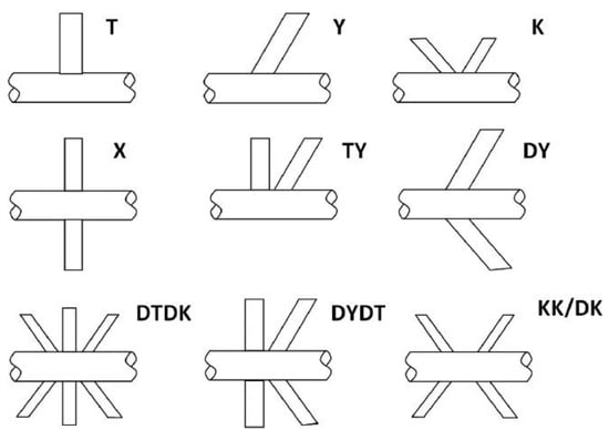
Figure 1. Typical tubular joints in offshore structures (no permission required, under CC BY-NC-ND license) [1].
The ability of a joint to bear subjected loads is vital for the safe and continuous operation of the facility. Excessive operational loads, cyclones, and tsunamis can cause fatigue damage to the joint, while material and construction flaws reduce the load capacity of the joint. Third-party damages caused by object drop and collision with vehicles during installations, inspection, or hostile strikes can damage structural joints. Additionally, corrosion, an obvious process in the humid offshore climate, is a major cause of pipeline failure. It degrades the joints by thinning the walls, causing stress concentration at the affected zone and modifying the nearby stress and strain field. Corrosion diminishes the load capacity of the joint and thus the whole structure. Reinforcing these critical joints may be necessary to regain or increase the load capacity or rectify the damage. Besides analytical calculations for simple joints, complex tubular joints are analyzed using numerical methods (such as finite element analysis) or experimentation. Various researchers have investigated the joint reinforcement methods, and some have developed mathematical models based on the data obtained in numerical or experimental studies. A single article accumulating the famous techniques for joint rehabilitation was missing in the literature. Researchers reviewed the advantages and disadvantages of the various tubular joint rehabilitation techniques commonly employed in the offshore sector. A viable alternative to conventional methods, FRP reinforcement, is explored, and the challenges in its application to offshore tubular joints are discussed. Researchers presents a quick overview of the techniques and may help better rehabilitation method selection. Due to extensive utilizations and various configurations, stiffener welding and composites have been discussed in more detail than other options.
Loads on Offshore Joints
Loads on a tubular joint can be axial tensile, axial compressive, in-plane bending (IPB), or out-plane bending (OPB), as presented in Figure 2. These loads can be present in some combination or one at a time.
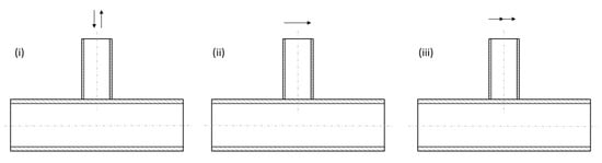
Figure 2. Possible loads on tubular joints. (i) Axial tensile/compressive, (ii) in-plane bending, (iii) out-of-plane bending.
While the nominal member stresses in most tubular structures may be within the allowable stress, the complicated geometry of the tubular joint can lead to considerable stress amplifications [2]. Stress concentration is caused at the interface due to geometry change and weld toe, as presented in Figure 3. Depending on the geometry of joints and the type of applied load, plastic failure of the chord, cracking of the brace-chord weld line, separation of the brace from the chord, cracking of the brace, local buckling, shear failure of the chord between neighboring braces, and lamellar ripping of the chord are typical modes of joint failure. Failure of a typical joint imparts extra load to other nearby structural members and may cause damage to these members, with the subsequent collapse of the whole structure.
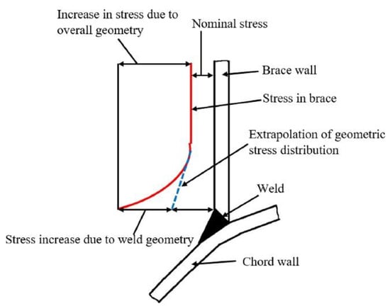
Figure 3. Stress distribution in typical tubular joints (no permission required, under CC BY-NC-ND license) [1].
Fatigue cracks normally begin at the weld toe near the brace-chord interface, where the structural discontinuity induces a high-stress concentration. The total stress at a joint is the summation of all stresses in a tubular joint [3]. The nominal stress calculated using beam theory neglects the localized weld effect and geometric discontinuity. The difference in the geometry of the brace and chord member of the joint results in a difference of deformation, causing a rise in stress at the interface known as geometric stress. The notch of the weld toe causes local stress, and its magnitude depends on the size and geometry of the weld. The effects of notch and weld profile are usually incorporated in the SN curve (stress-number of cycles to failure curve) of the joint. The hotspot stress is expressed as stress concentration factor (SCF) and used in the fatigue design of the tubular joints.
Common causes of fatigue damage in offshore structural joints are wave currents, wave-slamming vortex-induced vibrations, wind-induced vibrations, and transportation loads. To restrain failure of the critical joints, rehabilitation needs may be identified in routine maintenance or special inspections after a tsunami, cyclone, or an on-site accident.
2. Rehabilitation Needs Identification
Many oil and gas facilities worldwide were built decades ago and were not intended to be operational today. For example, 64 out of 190 (more than 30%) fixed offshore structures operated in the Malaysian region by PETRONAS had already exceeded their 30-year design life, and 20% will reach their design life in the next five years [4]. As such, a thorough life enhancement study is required to safely use these offshore facilities beyond their design life. As part of a structural inspection program, periodic inspections of offshore joints are usually conducted based on visual inspection and various techniques such as ultrasonic, radiographic, acoustic, eddy current, strain gauges, and vibration monitoring. A detailed risk analysis is carried out for unusual joints. The risk analysis identifies the frequency and consequences of joint failure based on the inspection data. In addition to the inspection data, design specifications, technical drawings, analysis/re-analysis reports, and maintenance and repair records are all considered in risk analysis. Each of these factors needs to be assigned specific weight/importance, and how they correlate plays an important role in decision-making. Based on the risk analysis, joints requiring rehabilitation are identified. The identified risk level is assessed, and temporary or permanent repair is recommended. The typical process of identifying the need for rehabilitation is presented in Figure 4.
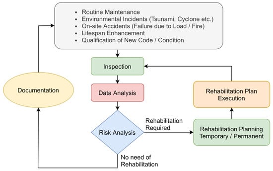
Figure 4. The typical process of rehabilitation requirement identification.
Establishing and maintaining an up-to-date database of methods, experts, suppliers, and costs is crucial to facilitate decision-making for an optimal rehabilitation plan. The rehabilitation may consist of load reduction on the endangered joint, adding a new member(s) to change the load path by transferring load to adjacent structural members, or removing the damaged joint by installing a new one. Sometimes a local rehabilitation scheme is employed around the joint. This rehabilitation process will have one or more operations, including welding, bolting, or adhesive joining.
3. Summary of Rehabilitation Methods
Rehabilitation methods for damaged or aged offshore joints have been discussed in detail. The selection of a particular rehabilitation strategy must be thoroughly examined. The nature of the damage and loads on a joint play a significant role. Table 2 presents a subjective assessment of the effectiveness of different rehabilitation techniques for certain applications. The efficacy of specific techniques, cost, installation time, and available technical expertise should also be considered. These characteristics of different rehabilitation methods are presented in Table 3. This comparison is based on subjective assessment by the authors. Clamping of pipelines can be quick but may require heavy machinery. Welding stiffeners involve hot work and may not be permitted sometimes. In many circumstances, fiber-reinforced polymers (FRP) can be preferred alternatives for rehabilitation. FRP repair of tubular joints has several advantages over other methods. However, research on FRP materials, epoxies, methods of composite reinforcement, curing of composite, especially in the underwater environment, and ways to improve the interface bond between the metal and composite needs further exploration. Investigations on the long-term performance and post-cure inspections will impart confidence to use composite reinforcement to repair critical joints permanently.
Table 2. Effectiveness of rehabilitation technique.
| Application | Rehabilitation Technique | |||||||
|---|---|---|---|---|---|---|---|---|
| Joint Replacement |
Collar Plate Welding | Doubler Plate Welding | Internal Ring Stiffeners |
Mechanical Clamping | Grouting | Composite Reinforcement |
||
| Defects | Corrosion | *** | ** | ** | * | ** | *** | *** |
| Crack | *** | ** | ** | * | *** | * | *** | |
| Dent | *** | ** | ** | ** | ** | ** | ** | |
| Upgradation | Static strength | *** | ** | * | * | * | * | *** |
| Stiffness | *** | * | ** | * | * | *** | ** | |
| Fatigue life | ** | ** | ** | * | * | * | *** | |
*: least effective, **: moderately effective, ***: highly effective.
Table 3. Comparison of rehabilitation techniques.
| Application | Rehabilitation Technique | ||||||
|---|---|---|---|---|---|---|---|
| Joint Replacement |
Collar Plate Welding | Doubler Plate Welding | Internal Ring Stiffeners |
Mechanical Clamping | Grouting | Composite Reinforcement |
|
| Application time | *** | ** | ** | ** | * | ** | * |
| Equipment required | *** | ** | ** | * | * | ** | ** |
| Cost | *** | * | * | ** | *** | ** | ** |
| Underwater applicability | * | * | * | * | * | ** | *** £ |
| Load penalty | - | * | * | ** | ** | *** | ** |
*: least in magnitude, **: moderate, ***: high. £: There will be challenges.
References
- Saini, D.S.; Karmakar, D.; Ray-chaudhuri, S. A review of stress concentration factors in tubular and non-tubular joints for design of offshore installations. J. Ocean Eng. Sci. 2016, 1, 186–202.
- Ávila, B.V.; Correia, J.; Carvalho, H.; Fantuzzi, N.; De Jesus, A.; Berto, F. Numerical analysis and discussion on the hot-spot stress concept applied to welded tubular KT joints. Eng. Fail. Anal. 2022, 135, 106902.
- Corigliano, P.; Crupi, V. Review of Fatigue Assessment Approaches for Welded Marine Joints and Structures. Metals 2022, 12, 1010.
- Nichols, N.W.; Khan, R. Structural integrity management system (SIMS) implementation within PETRONAS’ operations. J. Mar. Eng. Technol. 2015, 14, 61–69.
More
Information
Subjects:
Engineering, Marine
Contributors
MDPI registered users' name will be linked to their SciProfiles pages. To register with us, please refer to https://encyclopedia.pub/register
:
View Times:
906
Revisions:
3 times
(View History)
Update Date:
10 Mar 2023
Table of Contents


Notice
You are not a member of the advisory board for this topic. If you want to update advisory board member profile, please contact office@encyclopedia.pub.
OK
Confirm
Only members of the Encyclopedia advisory board for this topic are allowed to note entries. Would you like to become an advisory board member of the Encyclopedia?
Yes
No
${ textCharacter }/${ maxCharacter }
Submit
Cancel
Back
Comments
${ item }
|
${ item.createdUser.fullName }
${ item.createdAt }
${ item.vote }
${ item.reply }
Delete
${ reply.createdUser.fullName }
${ reply.createdAt }
${ reply.vote }
Delete
There is no reply to this comment~
${ item.replyTextCharacter }/${ item.replyMaxCharacter }
Submit
Cancel
More
No more~
There is no comment~
${ textCharacter }/${ maxCharacter }
Submit
Cancel
${ selectedItem.replyTextCharacter }/${ selectedItem.replyMaxCharacter }
Submit
Cancel
Confirm
Are you sure to Delete?
Yes
No