Your browser does not fully support modern features. Please upgrade for a smoother experience.
Submitted Successfully!
 +1 credit
Thank you for your contribution! You can also upload a video entry or images related to this topic.
For video creation, please contact our Academic Video Service.
| Version | Summary | Created by | Modification | Content Size | Created at | Operation |
|---|---|---|---|---|---|---|
| 1 | Reda Mankbadi | -- | 2231 | 2023-03-01 13:14:10 | | | |
| 2 | Catherine Yang | + 100 word(s) | 2334 | 2023-03-02 02:15:37 | | |
Video Upload Options
We provide professional Academic Video Service to translate complex research into visually appealing presentations. Would you like to try it?
Cite
If you have any further questions, please contact Encyclopedia Editorial Office.
Afari, S.; Golubev, V.; Lyrintzis, A.S.; Mankbadi, R. Active Noise Control Technology. Encyclopedia. Available online: https://encyclopedia.pub/entry/41777 (accessed on 24 June 2026).
Afari S, Golubev V, Lyrintzis AS, Mankbadi R. Active Noise Control Technology. Encyclopedia. Available at: https://encyclopedia.pub/entry/41777. Accessed June 24, 2026.
Afari, Samuel, Vladimir Golubev, Anastasios S. Lyrintzis, Reda Mankbadi. "Active Noise Control Technology" Encyclopedia, https://encyclopedia.pub/entry/41777 (accessed June 24, 2026).
Afari, S., Golubev, V., Lyrintzis, A.S., & Mankbadi, R. (2023, March 01). Active Noise Control Technology. In Encyclopedia. https://encyclopedia.pub/entry/41777
Afari, Samuel, et al. "Active Noise Control Technology." Encyclopedia. Web. 01 March, 2023.
Copy Citation
Reducing noise radiation via passive control may have adverse effects on the aerodynamic performance. Therefore, an alternative approach is to design the vehicle with some passive control built-in the design, which should be optimized for regular flight operations then engage active noise control (ANC) only in particular situations when the noise temporarily increases above the allowable level as in the vicinity of vertiport.
active control
noise
AAMV
UAV
rotorcraft
1. Zone Control
The first type of ANC is sound field cancellation or zone control. To execute a zone control, a zone of silence is needed around the sound source. One method for achieving this is the use of anti-noise. The basic principle is that if the noise at the target point is a simple wave, one can impose an identical wave to it with a 180 degrees phase shift to cancel it. An example of this mechanism is the noise cancelling headphones, first developed by Meeker of RCA [1]. Practical applications of this kind of mechanism are limited to relatively enclosed regions. Usually, a feedback loop is needed. A sensor measures the radiated sound, which is fed into a microprocessor to determine the anti-noise signal needed for sound suppression. Complete cancellation at a given point, in principle, can be achieve via an iterative process through the feedback mechanism. Ikelheimer & Nagel [2] considered a propeller surrounded by four speakers to create a zone of silence. The method worked best at the specific target location, but other locations saw increases in the sound pressure level. Increasing the number of speakers was found to be more effective. Deviating slightly from rotors, some successes have been seen in experiments by Koopmann et al. [3] with 10–20 dB noise reductions in centrifugal fans. This technique becomes unfeasible for open rotors as it would require a high acoustic impedance to counter the noise source for every observer location [2].
2. On-Blade Actuation
The second type of ANC is the modification or suppression of the sound generation, is the case where a modification is done on the blade to alter the radiation impedance of the original noise source for acoustic mitigation. Most active rotor noise control ideas fall under this mechanism or classification. Several decades of research and studies were directed towards BVI noise reduction, vibration reduction, and performance enhancement [4][5][6]. On-blade active rotor control methods such as higher harmonic control (HHC), individual blade control (IBC), trailing edge flap (TEF), blowing on or near the rotor blade have been tested as potential ways of altering the wake structure, and subsequently the reduction of the BVI effects [5].
Higher harmonic control system is an active vibration control mechanism where the rotor blades are oscillated at higher harmonics of the rotational speed. Although originally devised as a method for vibrational reduction, it was suggested as a potential method for reducing BVI in the late 1990s [6]. However, it was determined that when implemented, fuselage vibration levels were drastically increased when driven at low BVI noise frequencies [7][8]. This can be reduced by applying the excitation at a higher harmonic frequency, which ultimately led to the development of the individual blade control methods. eVTOLs are generally scaled down variants of rotorcrafts with multiple rotor systems. Applying this method of active rotor control might prove quite deleterious as the vibrations or excitation of the oscillations from all the rotors might introduce some structural issues and may reduce the level of comfort in the fuselage/cabin. Several active control research have been done particularly for helicopter rotors with little to none done for small-scale rotors for UAVs. However, the researchers review a few techniques and their feasibility and successes.
Anobile et al. [9] developed a low-frequency controller geared towards reducing helicopter rotor BVI noise. The utilize an active twist rotor concept via torque load distributions at 2/rev frequency. They apply this methodology numerically to a scaled Bo-105 4-bladed helicopter main rotor, with a radius of 2 m, a constant chord of 0.212 m, linear twist of -8 degrees, and a rotational speed of 109 rad/s. The general Kussner-Schwarz theory is employed to determine the unsteady aerodynamic loads associated with the profile downwash. Aeroelastic computations are performed to account for the blade deformation and its effects on the wake. The wake inflow is predicted using a free-wake boundary element solver. They perform open-loop control using the active twist, which showed that a 2/rev actuation was effective in reducing the BVI sound pressure level by about 2 dB. However, this also resulted in an increase in vibratory loads and low frequency noise of about 3 dB. Using the microphones below helicopter and at the skid ends (Figure 1), a closed loop controller was developed which resulted in a maximum BVI sound pressure level reduction of 6 dB at the retreating side.
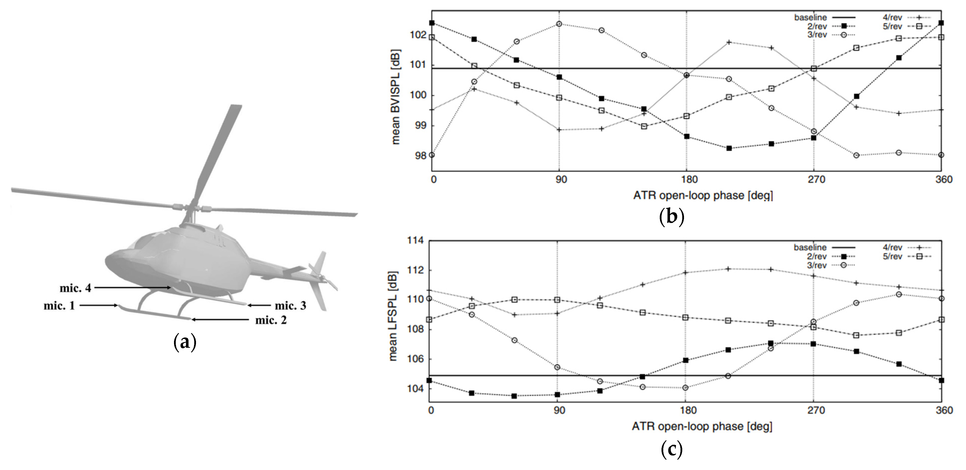
Figure 1. (a). Location of microphones; (b). Mean BVI sound pressure level for open-loop controller; (c). Mean Low-frequency Sound Pressure Level [9]. Reprinted with permission from Anobile, A. (2016).
One of the earliest proven tests of the concept of on-blade actuation for harmonic noise control was the full-scale “Boeing SMART” rotor [10]. They utilized an active trailing edge flap for the blade noise control. The results showed that placing the controls near the tips is an effective thickness noise control, with the total thickness noise reduced to about 50% in amplitude.
More recently, Sargent and Schmitz [4][11][12] performed experiments with a 1/7th scale rotor, where they used tip mass ejection to attempt to reduce specifically the in-plane thickness noise. They implement this by extracting out the mass flow rate equation and comparing with the Ffowcs-Williams Hawking equation (Ffowcs Williams and Hawkings, 1969). For an idealized point source ejecting mass into a quiescent medium, the jet mass flow rate is given as [12]:
With velocity of source moving with respect to the medium V→source= Ω→ x r→jet+V→∞. Assuming ρjet=ρ0 then:
Comparing with FWH equation, we get the permeable mass and momentum injection terms as:
where u→=V→jet+V→source and v→=V→source. The anti-noise acoustic pressure was derived to be the combination of the pressure due to the mass injection term, and that due to the momentum injection. This method resulted in a reduction in the peak negative amplitude of the test rotor’s radiated noise by 5 Pa at the target microphone, but was impractical as the required mass flow rate needed required a high exit jet velocity profile (see Figure 2).
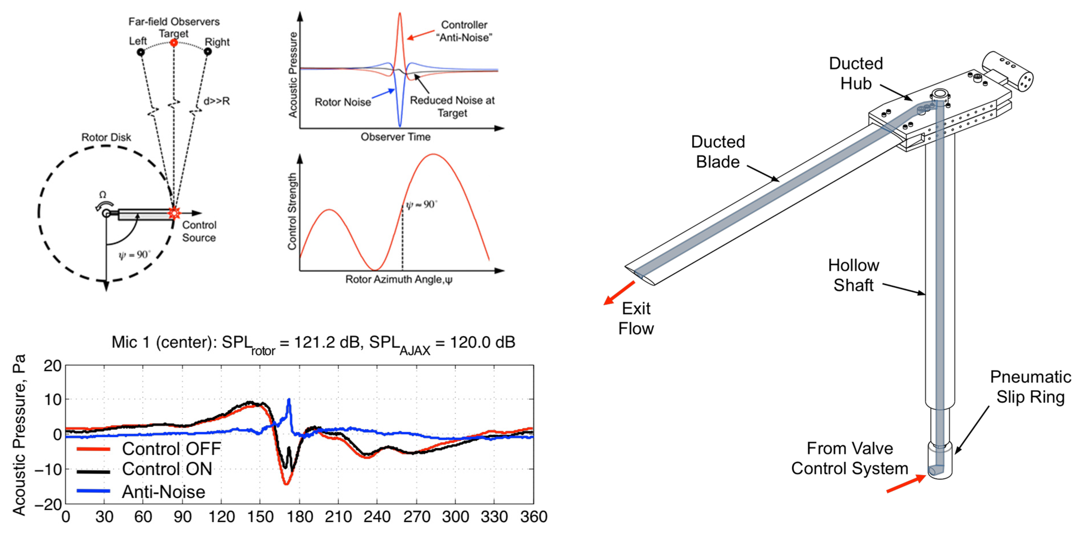
Figure 2. Experimental Setup for tip air blowing [11]. Reprinted with permission from Sargent, D.C. (2014).
Shi et al. [13] explored the use of trailing edge winglets for unsteady force excitation. This method specifically looks to target the rotor thickness noise. The method involves the application of an unsteady aerodynamic force to excite a secondary or anti-sound wave. This excitation was done with the use of a trailing edge winglet near the tip of the rotor (see Figure 3).
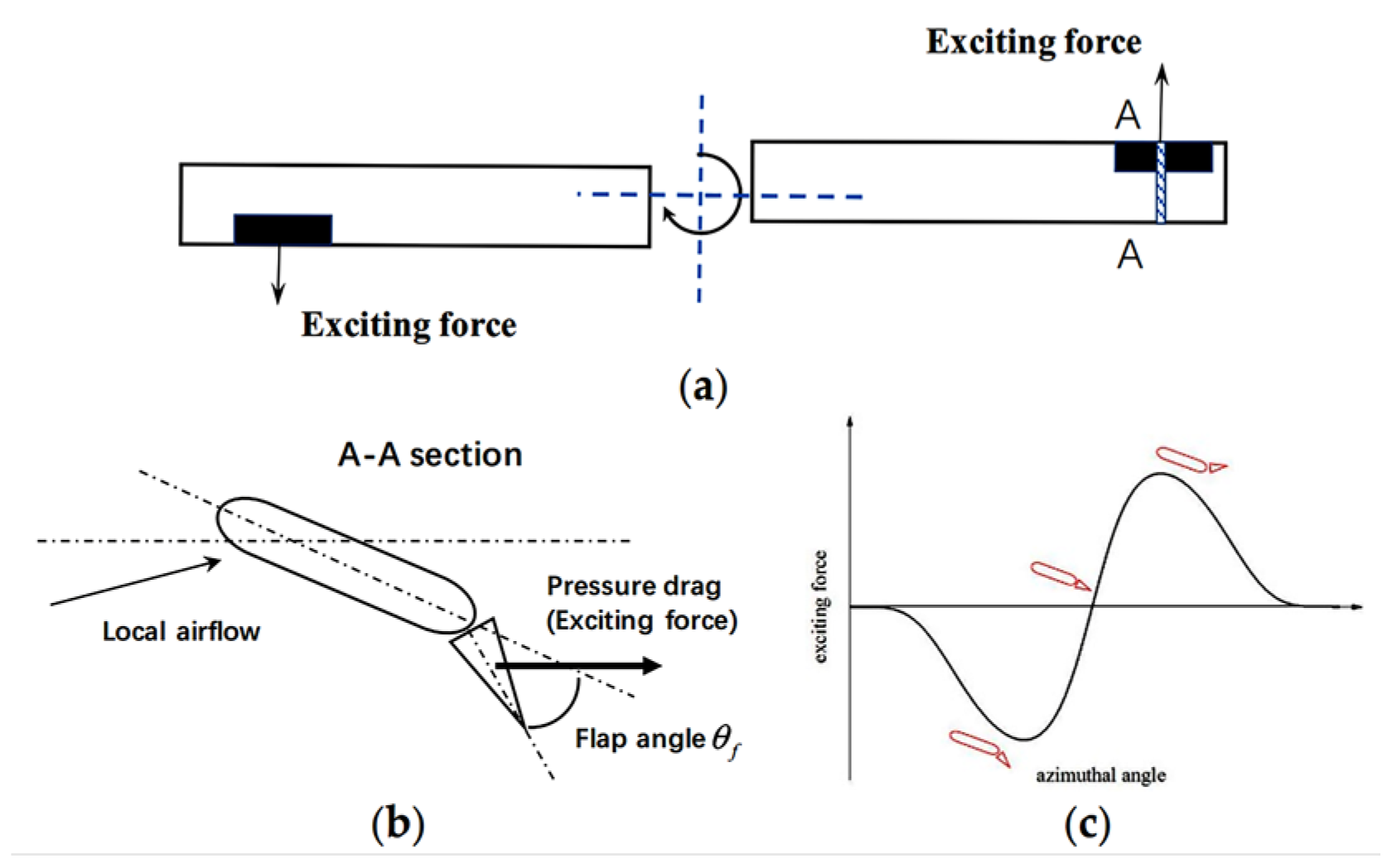
Figure 3. Schematic of experimental setup [13].
A harmonic formulation for prescribing the motion of the trailing edge winglet actuator was devised:
where Fn is amplitude, n is the harmonic, ψ and ψo are azimuthal angle and initial excitation angle. The limitations of this approach are that the formulation of the anti-noise actuation depends on the correct amplitude of the forcing function, Fn, the harmonic number, and the phase angle (see Figure 4). There was no direct correlation to obtain the exact wave form without experimentation.

Figure 4. Effect of force amplitude on noise reduction. (a) Fn = 2 N, (b) Fn = 4 N, (c) Fn = 8 N [13].
Another approach was devised by Yang et al. [14] by canceling the in-plane thickness noise with a point source loading noise formulation. They utilize a single-bladed rotor with a radius of 5.79 m, a chord of 0.381 m, and an advancing-tip Mach number of MAT=0.8 with a target observer 100 Radii away from the center of the rotor. From the differential form of the FWH equation, the loading noise is formulated by equating the thickness noise at an observer to the loading noise:
This technique was implemented both numerically and experimentally using a flap for a single observer and a single rotor blade.
They tested two actuators—an active flap and a winglet on the blades and found that the active flap resulted in about 3 dB noise reduction over an azimuth range of 150 to 210 degrees, and the winglet showed more than 6 dB reduction over an azimuthal range of 120 to 240 degrees in the rotor plane.
All the discussed methods have proven to be successful in cancelling thickness noise, but the practicality of the applications is still questionable. The use of the active flaps showed great promise, but its effects on the blade loading and performance, as well as the structural integrity of the blades is yet to be understood. Additionally, the methods discussed have all been tested on single rotor blades, and thus their applicability in multi-bladed and multi-rotor systems must be explored.
3. Active Tonal Noise Control of Multi-Rotor Air Mobility Vehicles at Approach
ANC of rotors has been investigated recently by [15], Yang et al. (2019). [11], and [10], among others. They argued that it is the in-plane fundamental thickness noise that needs to be reduced as it becomes the significant source during approach. This is particularly true with the low-frequency high amplitude noise. They proposed placing a point actuator on the blades to produce some loading noise to cancel the in-plane thickness noise. Actuators such as a flap, winglets and tip-blowing have been investigated. The above-mentioned work is, however, limited to the case of a single rotor, and a single actuator. Single point actuators make the loading actuation per area too excessive. Extension to AAM multi-rotors with distributed actuators is needed and is the subject of Afari & Mankbadi’s [16] work.
An Active Noise Control (ANC) technology is developed by Afari & Mankbadi [16] to reduce the in-plane thickness noise associated with multi-rotor Advanced Air Mobility Vehicles (AAM). They considered two in-line rotors and showed that the FWH-determined actuation signal can produce perfect cancellation at a point target. However, the practical need is to achieve noise reduction over an azimuthal zone, not just a single point. Furthermore, for practical applications the single point actuator is replaced by distributed micro actuators system (Figure 5). Note that Fs is the span-wise force, Fc is the chord-wise force, and Lr is the resultant loading vector in the target observer direction. To achieve this zonal noise reduction, an optimization technique is developed to determine the required actuation signal produced by the on-blade distribution of embedded actuators on the two rotors.

Figure 5. Sketch showing the directivity of the forces and the loads in relation to the observer as well as the dual piezo speaker configuration [16].
4. Calculation of Distributed Array of Loading Actuators
A distributed array of acoustic actuators is used for imposing the required loading noise needed to reduce the noise at a set of azimuthal observers. From the Farassat’s formulation 1A [17], the total acoustic pressure at an observer point is given as:
To find the loading solution, the researchers set p′L(x,t)=−p′T(x,t). If the researchers assume the blade surface to be a compact source, the loading noise formulation becomes:
where Lr is the component of the loading solution in the radiation direction, nB and nR are the number of blades and number of rotors, respectively. The anti-noise loading Lr needed is then solved by feeding the values of the thickness noise, p′T, and getting values of the observer distance r, the Mach number in the radiation direction Mr, and the flight Mach number M from the computation of the thickness noise into the ordinary differential equation shown in Equations (8) and (9). A fourth order Runge-Kutta algorithm is employed to solve for the loading “anti-noise” solution, which is then fed into Equation (7) to find the corresponding anti-noise pressure signal.
where
Target Zone: For a zone of target observers, a new loading term, LrA, is introduced such that:
where Kj and Bj are the coefficients and tuning parameters that needs to be solved. This function is looped over each blade and each rotor, and thus the number of tuning parameters increase. The resulting optimized loading solution, Lr as well as far-field noise signal are shown in Figure 6. The far-field pressure field is also computed and shown in Figure 7. It can be seen a slightly imperfect total cancellation. This occurs because the loading actuator must account for each observer peak, which is offset, and is not at the same temporal location. For the specific geometry, this produced about 9 dB reduction in the in-plane thickness noise during forward flight of the two rotors. Note that although the method works well for thickness noise control, broadband noise might prove to be important for AAM, and thus the method would need to be extended for BBN control.
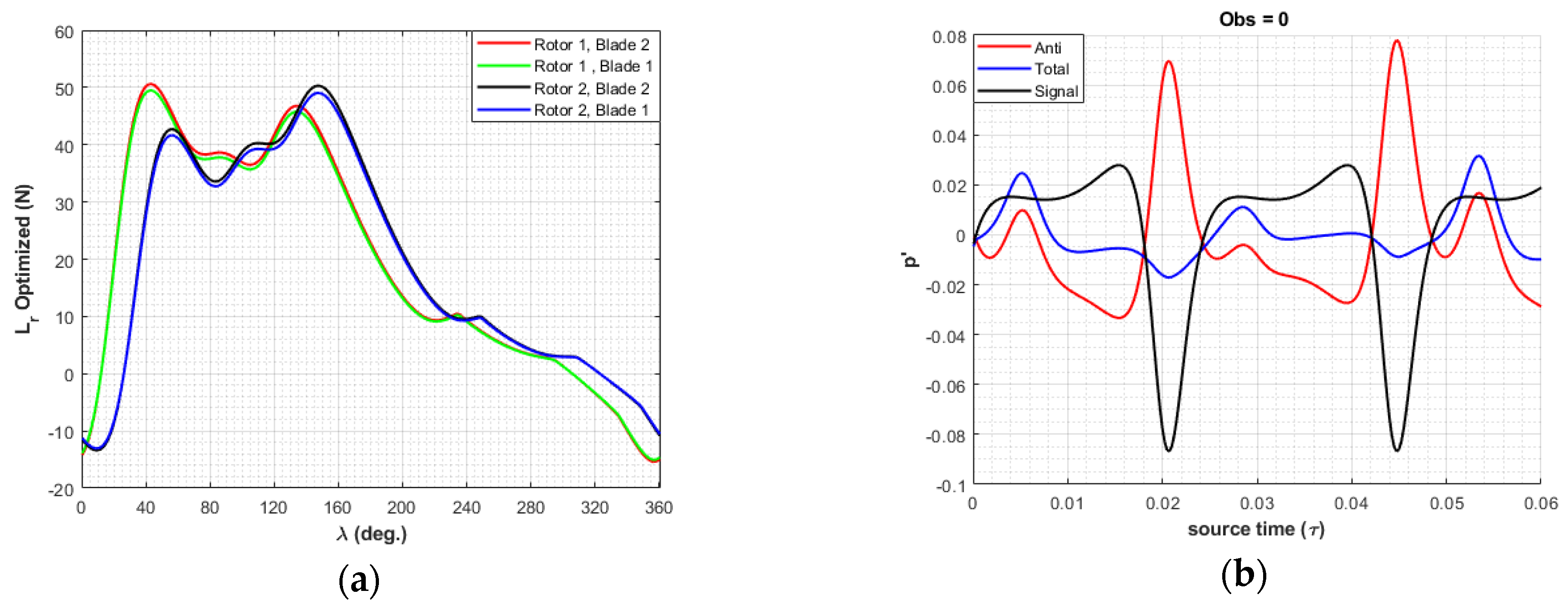
Figure 6. (a) Optimized Loading Solution, Lr, for each blade; (b) Total Noise at target observer, ψobs=0o.
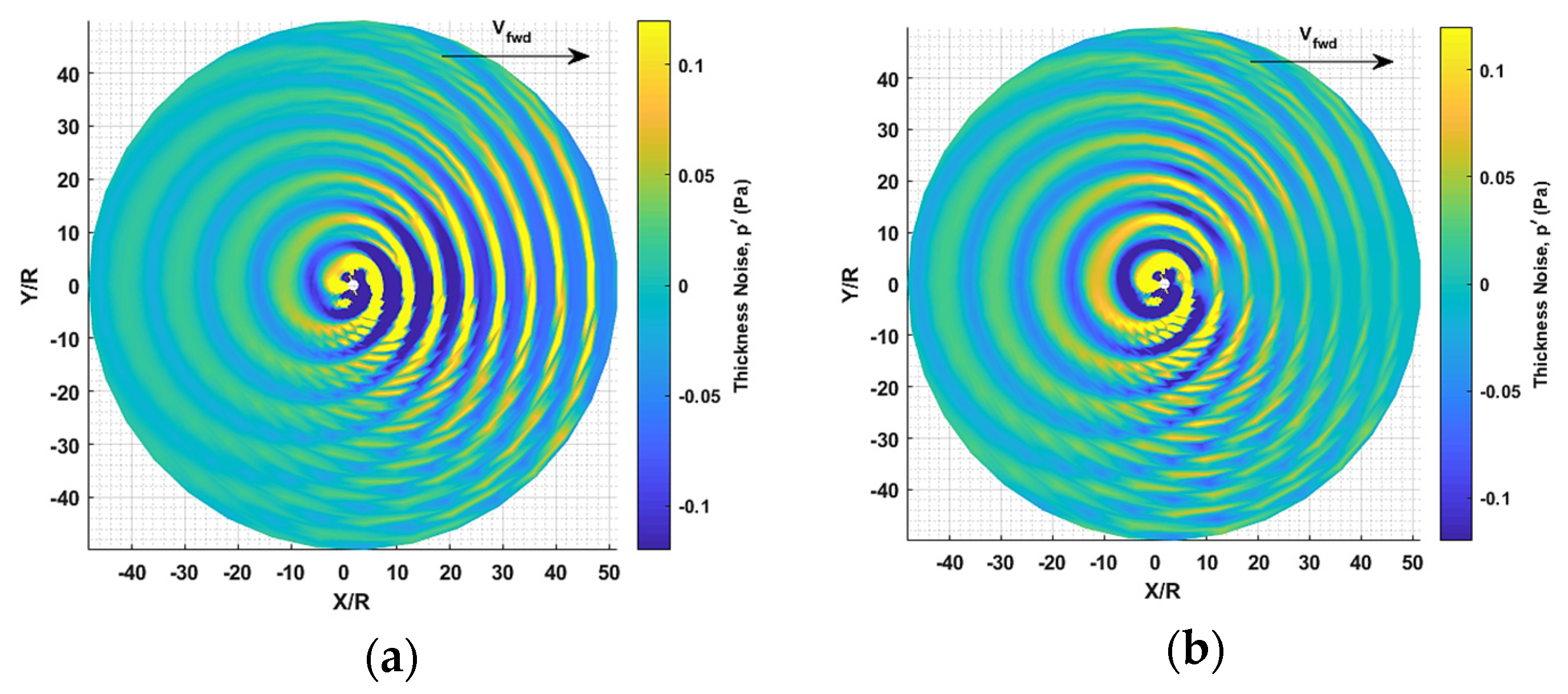
Figure 7. Contour plots of acoustic pressure showing (a): No control, and (b): With control for a zone of observers [16].
References
- Cunefare, K. Active Noise Control. Special Lay-Language Paper for the 75th Anniversary Meeting of the Acoustical Society of America; ASA: Melville, NY, USA, 2004.
- Ikelheimert, B.J.; Nagel, R.T. Active noise control of an unducted model propeller. In Proceedings of the 3rd AIAA/CEAS Aeroacoustics Conference, Atlanta, GA, USA, 12–14 May 1997; pp. 441–447.
- Koopmann, G.H.; Koopmann, W.; Chen, W. Active Noise Control to Reduce the Blade Tone Noise of Centrifugal Fans. J. Vib. Acoust. Stress Reliab. Des. 1988, 110, 377–383.
- Sargent, D.C. Active Jet Acoustic Control of Low Frequency, In-Plane Helicopter Harmonic Noise; University of Maryland: College Park, MD, USA, 2012.
- Yu, Y.H.; Gmelin, B.; Splettstoesser, W.; Philippe, J.J.; Prieur, J.; Brooks, T.F. Reduction of helicopter blade-vortex interaction noise by active rotor control technology. Prog. Aerosp. Sci. 1997, 33, 647–687.
- Hardin, J.C.; Lamkin, S.L. Concepts for reduction of blade/vortex interaction noise. AIAA J. Aircr. 2012, 24, 120–125.
- Brooks, T.F.; Booth, E.R.; Jolly, J.J.R.; William, J.R.; Yeager, T.; Matthew, J.R.; Wilbur, L. Reduction of Blade-Vortex Interaction Noise through Higher Harmonic Pitch Control; American Helicopter Society: Phoenix, AZ, USA, 1990; Volume 35.
- Splettstoesser, W.R.; Lehmann, G.; van der Wall, B. Higher harmonic control of a helicopter rotor to reduce blade-vortex interaction noise. Z. Fluowissenschaften 1996, 14, 109–116.
- Anobile, A.; Bernardini, G.; Gennaretti, M.; Testa, C. Synthesis of Active Twist Controller for Rotor Blade–Vortex Interaction Noise Alleviation. J. Aircr. 2016, 53, 1865–1874.
- Sim, B.W.; JanakiRam, R.D.; Lau, B.H. Reduced in-plane, low-frequency noise of an active flap rotor. J. Am. Helicopter Soc. 2014, 59, 1–17.
- Sargent, D.C.; Schmitz, F.H. Fundamental experimental studies supporting active-jet acoustic control of in-plane rotor harmonic noise. J. Aircr. 2014, 51, 434–446.
- Caleb Sargent, D.; Schmitz, F.H. Fundamental experimental studies supporting on-blade tip air blowing control of in-plane rotor harmonic noise. In Proceedings of the 18th AIAA/CEAS Aeroacoustics Conference (33rd AIAA Aeroacoustics Conference), Colorado Springs, CO, USA, 4–6 June 2012.
- Shi, Y.; Li, T.; He, X.; Dong, L.; Xu, G. Helicopter Rotor Thickness Noise Control Using Unsteady Force Excitation. Appl. Sci. 2019, 9, 1351.
- Yang, T.; Brentner, K.S.; Corle, E.; Schmitz, S. Study of active rotor control for in-plane rotor noise reduction. J. Aircr. 2019, 56, 179–190.
- Gopalan, G.; Schmitz, F. Far-Field Near-In-Plane Harmonic Main Rotor Helicopter Impulsive Noise Reduction Possibilities. Am. Helicopter Soc. Annu. Forum 2008, 64, 675.
- Afari, S.O.; Mankbadi, R.R. Active Noise Control of Multi-Rotor Advanced Air Mobility Vehicles. J. Am. Helicopter Soc. 2022, 63.
- Brentner, K.S. Modeling aerodynamically generated sound: Recent advances in rotor noise prediction. In Proceedings of the 38th Aerospace Sciences Meeting and Exhibit, Reno, NV, USA, 10–13 January 2000.
More
Information
Subjects:
Engineering, Aerospace
Contributors
MDPI registered users' name will be linked to their SciProfiles pages. To register with us, please refer to https://encyclopedia.pub/register
:
View Times:
1.0K
Revisions:
2 times
(View History)
Update Date:
02 Mar 2023
Table of Contents


Notice
You are not a member of the advisory board for this topic. If you want to update advisory board member profile, please contact office@encyclopedia.pub.
OK
Confirm
Only members of the Encyclopedia advisory board for this topic are allowed to note entries. Would you like to become an advisory board member of the Encyclopedia?
Yes
No
${ textCharacter }/${ maxCharacter }
Submit
Cancel
Back
Comments
${ item }
|
${ item.createdUser.fullName }
${ item.createdAt }
${ item.vote }
${ item.reply }
Delete
${ reply.createdUser.fullName }
${ reply.createdAt }
${ reply.vote }
Delete
There is no reply to this comment~
${ item.replyTextCharacter }/${ item.replyMaxCharacter }
Submit
Cancel
More
No more~
There is no comment~
${ textCharacter }/${ maxCharacter }
Submit
Cancel
${ selectedItem.replyTextCharacter }/${ selectedItem.replyMaxCharacter }
Submit
Cancel
Confirm
Are you sure to Delete?
Yes
No