Submitted Successfully!
To reward your contribution, here is a gift for you: A free trial for our video production service.
Thank you for your contribution! You can also upload a video entry or images related to this topic.
Version Summary Created by Modification Content Size Created at Operation
1 -- 3429 2023-02-15 10:02:15 |
2 Reference format revised. + 10 word(s) 3439 2023-02-16 07:33:23 |

Video Upload Options

Do you have a full video?

Confirm

Are you sure to Delete?
Cite
If you have any further questions, please contact Encyclopedia Editorial Office.
Rak, G.; Hočevar, M.; Kolbl Repinc, S.; Novak, L.; Bizjan, B. Methods for Measurement of Free Water Surface. Encyclopedia. Available online: https://encyclopedia.pub/entry/41249 (accessed on 07 July 2024).
Rak G, Hočevar M, Kolbl Repinc S, Novak L, Bizjan B. Methods for Measurement of Free Water Surface. Encyclopedia. Available at: https://encyclopedia.pub/entry/41249. Accessed July 07, 2024.
Rak, Gašper, Marko Hočevar, Sabina Kolbl Repinc, Lovrenc Novak, Benjamin Bizjan. "Methods for Measurement of Free Water Surface" Encyclopedia, https://encyclopedia.pub/entry/41249 (accessed July 07, 2024).
Rak, G., Hočevar, M., Kolbl Repinc, S., Novak, L., & Bizjan, B. (2023, February 15). Methods for Measurement of Free Water Surface. In Encyclopedia. https://encyclopedia.pub/entry/41249
Rak, Gašper, et al. "Methods for Measurement of Free Water Surface." Encyclopedia. Web. 15 February, 2023.
Methods for Measurement of Free Water Surface
Edit

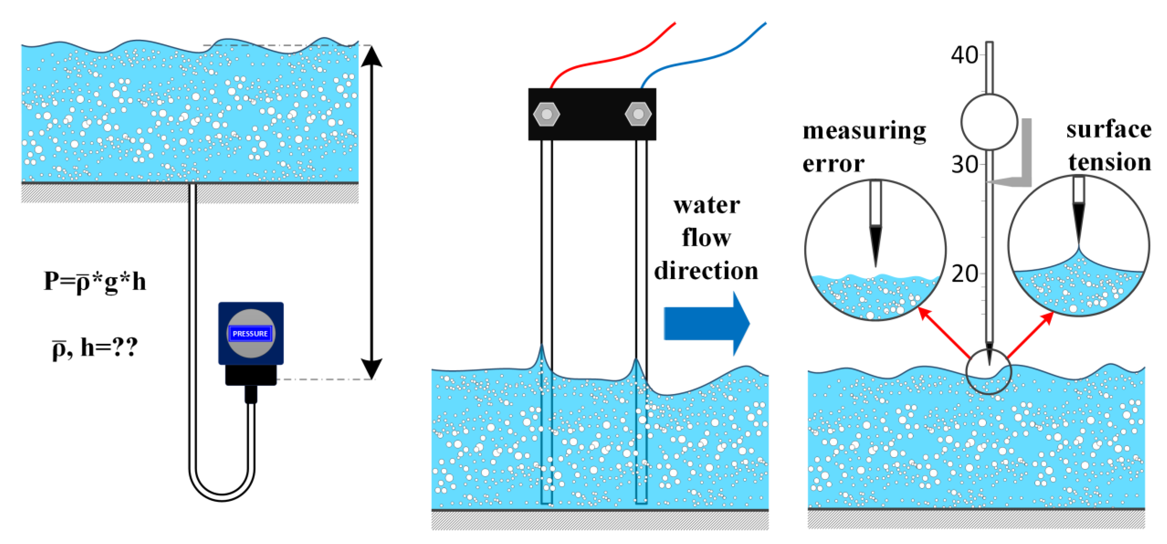
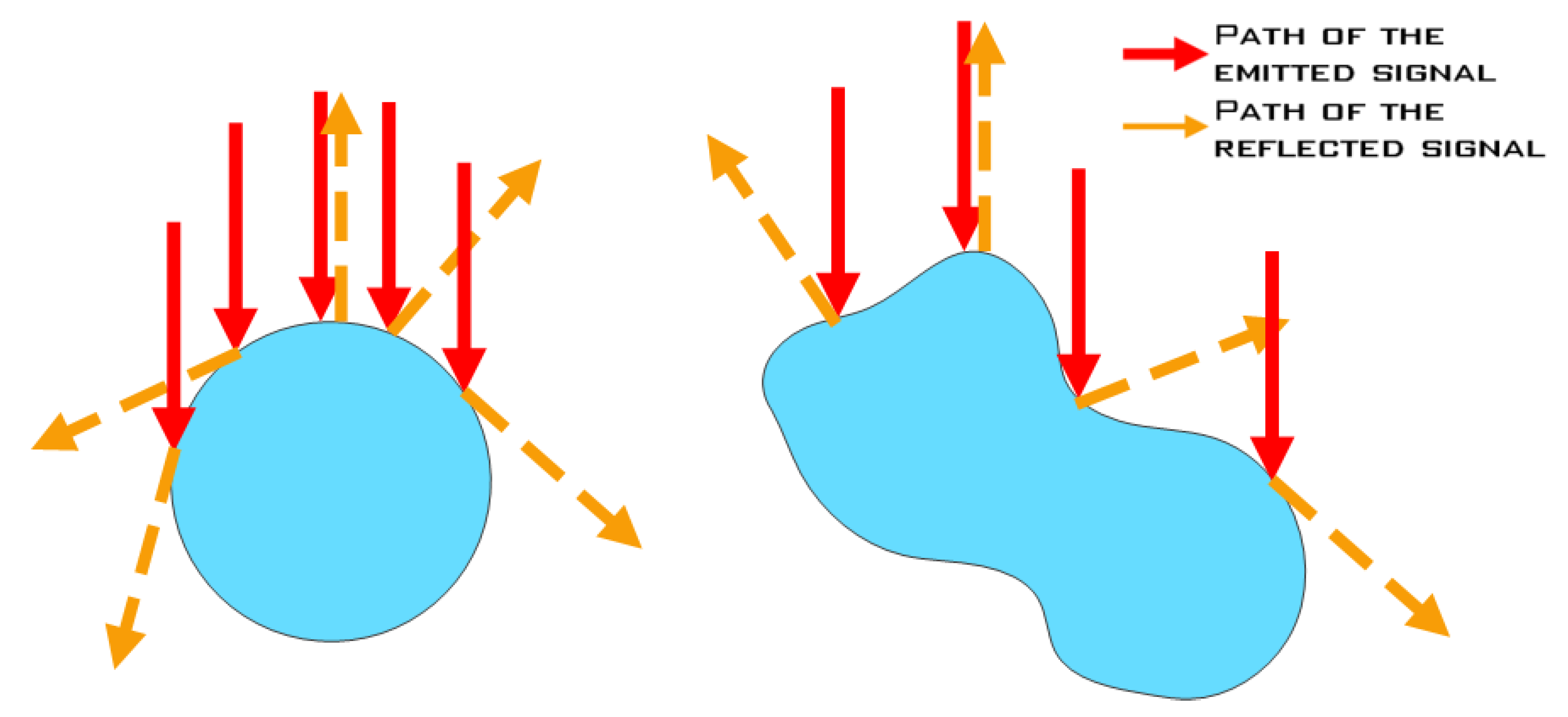
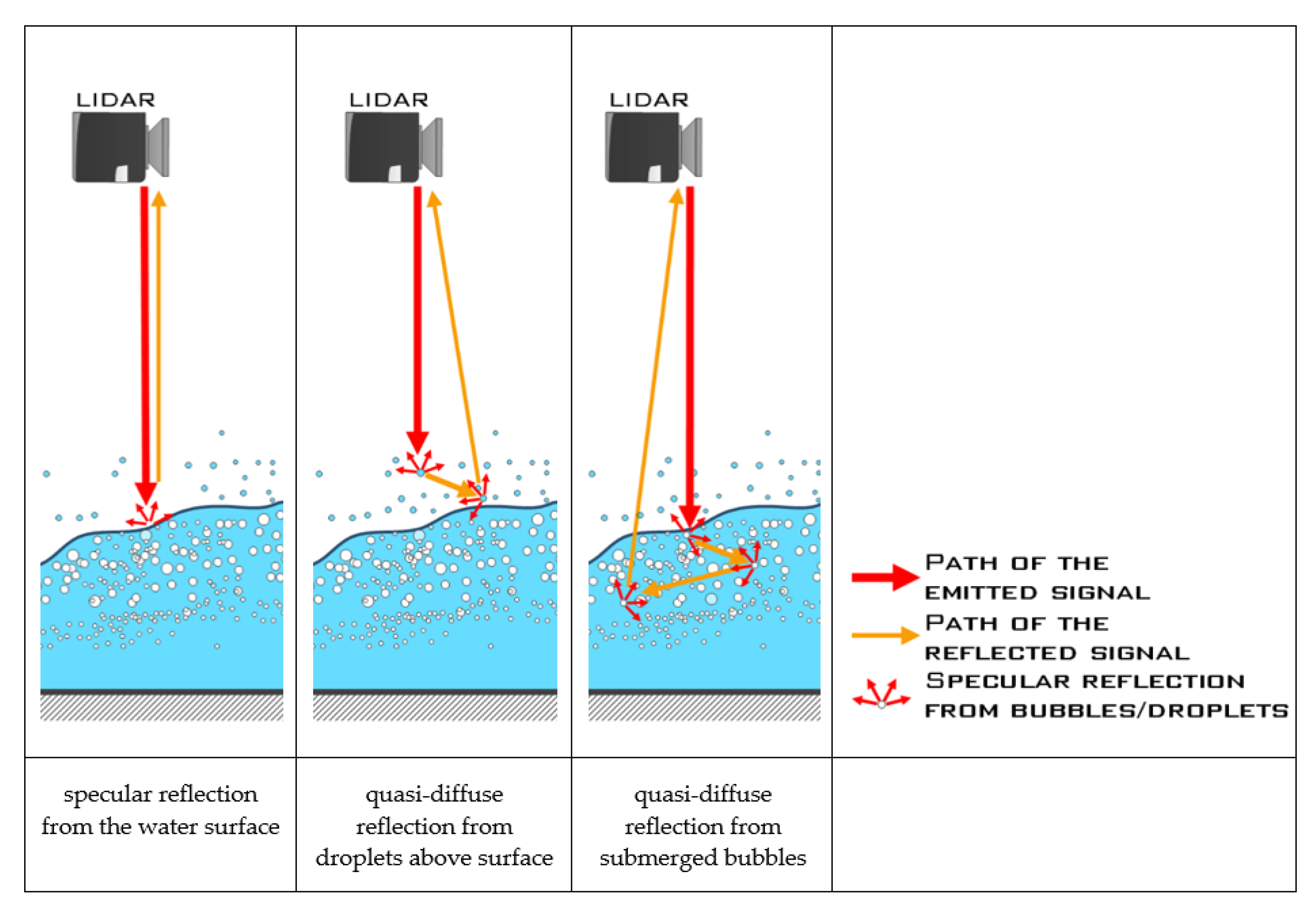
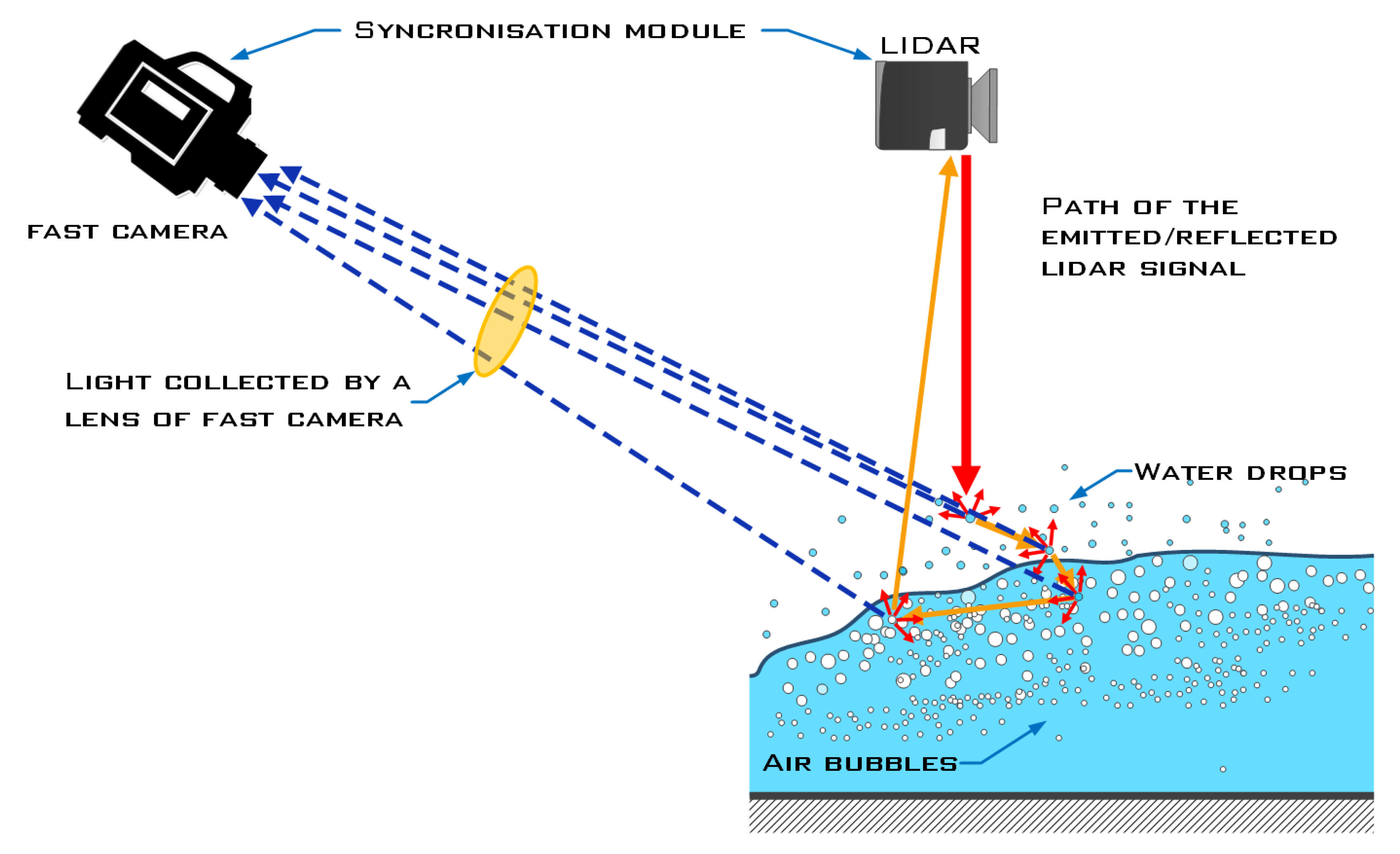
Turbulent free-surface flows are encountered in several engineering applications and are typically characterized by the entrainment of air bubbles due to intense mixing and surface deformation. The resulting complex multiphase structure of the air–water interface presents a challenge in precise and reliable measurements of the free-water-surface topography. Conventional methods by manometers, wave probes, point gauges or electromagnetic/ultrasonic devices are proven and reliable, but also time-consuming, with limited accuracy and are mostly intrusive. Accurate spatial and temporal measurements of complex three-dimensional free-surface flows in natural and man-made hydraulic structures are only viable by high-resolution non-contact methods, namely, The light detection and ranging (LIDAR)-based laser scanning, photogrammetric reconstruction from cameras with overlapping field of view, or laser triangulation that combines laser ranging with high-speed imaging data. In the absence of seeding particles and optical calibration targets, sufficient flow aeration is essential for the operation of both laser- and photogrammetry-based methods, with local aeration properties significantly affecting the measurement uncertainty of laser-based methods.

free water surface measuring methods laser scanning high-speed imaging two-phase flow turbulent flow

1. Introduction

Precise and reliable measurements of complex hydraulic phenomena including high-speed flow and particularly aerated flow features are essential for obtaining new information and knowledge about water flow structures and accompanying processes [1]. Comprehensive knowledge of these phenomena combined with the capability for their accurate modelling is required to avoid under-dimensioned or otherwise poorly constructed hydraulic structures such as high-speed outlets, spillways of HPP, sediment bypass tunnels, desilting and fish migration facilities, drop shafts, etc. [2]. The knowledge of hydraulic phenomena is well advanced mainly in subcritical flows but is still limited in supercritical flows and transitions to two- or multi-phase flows [2]. Such flows are present in a wide range of applications in civil, chemical, environmental, mechanical, mining and nuclear engineering.
Most free-surface flows in hydraulic structures are turbulent and characterized by a varying degree of air bubble entrainment due to surface deformation and high shear stresses that exceed surface tensions resisting interfacial breakup [3]. Free-surface flows with high Reynolds and Froude numbers (approximately Re > 104 and Fr > 3, respectively) are highly complex, non-homogeneous and non-stationary [4][5]. The surface is undulating, and velocity variations change the height according to Bernoulli equation. Due to shear forces often prevailing over surface tension, surface break-up is frequent, leading to the formation of both water-entrained bubbles and droplets flying above the surface [6]. A high Reynolds number of the flow causes bubbles and droplets to form a very prominent non-spherical shape and high velocity [7]. Another interesting feature of flows at high Reynolds and Froude numbers is their ability to form large standing and fluctuating quasi periodic waves at confluences [8]. Standing wave heights at the confluences are often several times higher than both flows in front of the confluence. The surface of standing waves features similar properties as the aforementioned aerated flows with a heavily undulating and uneven surface, many entrapped bubbles and flying droplets. Standing waves at the confluence may also form a concave surface, which is difficult to capture using available measurement methods, often preventing the unambiguous determination of the free-surface position and height.
Besides the evident necessity of correctly dimensioning hydraulic structures to prevent overflowing or excessive recirculation when complex turbulent and highly aerated flows are expected, another important design consideration is the impact of turbulent water mixing, hydraulic jump and consequent water aeration, which affect the ecological conditions in surface water bodies [9]. Oxygen concentration in the water is very important when determining surface water quality. Turbulent mixing helps to minimize the oxygen deficit and encourages positive changes in the microbiological metabolism of the flow [10].
The conventional approach to hydraulic structure design has been to rely upon fundamental hydrodynamics and theoretical studies, combined with a range of historically proven designs [3]. Often, this has included construction of scaled-down models with manageable dimensions so that classic flow measurement methods (e.g., manometers, wave probes and point gages) could be utilized to determine the water flow behavior. Although adequate for simpler hydraulic structures that had been constructed for many centuries, such a simplistic design strategy often cannot meet the requirements of demanding supercritical flow designs as it involves significant trial-and-error which is costly, time-consuming and potentially dangerous under unforeseen extreme operating conditions (e.g., flooding, erosion, etc.). The greatest design challenges are experienced when high-speed and/or highly aerated flows are involved [2].
To reduce the cost and risk associated with the design and operation of hydraulic structures, the accurate modeling of water flow and related phenomena is of great importance. Modern design methods include both experimental measurements on scaled-down hydraulic models, as well as numerical simulations by computation fluid dynamics (CFD). The capability of modern CFD simulations to simultaneously calculate many flow-related quantities (velocity, pressure, volume fraction…) in high resolution is certainly attractive, especially when simulation results are presented in a visually appealing manner. Nevertheless, the accuracy and reliability of numerical simulations are still questionable, since simulation results can be very sensitive to the wide range of computational parameters that have to be set by the user [6]. Additionally, each CFD model requires calibration and verification by experimental measurement methods, and often the amount of quality measurement data is insufficient to do so. For this reason, the development of hydraulic measurement techniques with high spatial and temporal resolution is a priority to improve the surface measurements and turbulent surface flow modelling in conjunction with CFD simulations. Without doubt, a great deal of insight into the operation of hydraulic structures has been gained over decades of using flow measurement methods such as point gauges and manometers. On the other hand, immense advances in the last two decades in laser- and photogrammetric-based methods for terrestrial scanning have also led to the limited adaptation of these methods for the measurement of free-surface flows [11].

2. Methods for Measuring Free Water Surface

2.1. General Classification

Numerous different methods exist for the purpose of measuring the free water surface. These methods can be classified with respect to their intrusiveness (contact vs. non-contact), spatial resolution (point measurements vs. 2D/3D spatial measurements) and temporal resolution (low vs. high sampling rate).
Static water levels with little or no aeration present are mostly measured by well-established flow measurement devices such as U-manometers [12], point gauges [13][14], wave probes [15][16] and ultrasonic sensors [17][18]. On the other hand, flows with an aerated air–water surface are most frequently analyzed by the means of ultrasonic sensors and high-speed video cameras in a side-view perspective, while laser-based technologies have also received increased research attention in recent years [19]

2.2. Manometers, Wave Probes, Point Gauges

Steady water flows with a negligible presence of aeration allow for the use of rather inexpensive and well-established measurement methods such as manometers, wave probes and point gauges (Figure 1). Manometers are among the oldest pressure measurement instruments and operate by indicating differential pressure proportionally to the liquid column weight due to the difference in liquid pressure on both ends of connecting tubes. Most commonly, manometers are designed in the form of a U-tube where measured pressure difference is proportional to the difference in liquid height between the left and right vertical tube section. Another well-known design is a bulb manometer where the liquid in a tube is open to the measured medium on one side while it seals the reference gas contained within a bulb on another side.
Figure 1. Principle of operation of manometers (left), wave probes (middle) and point gauge (right), with common issues found.
The two main operational challenges of manometer depth measurement are errors incurred by the effect of flow velocity and presence of bubbles or impurities. When velocity of the fluid v above the manometer probe is higher than zero, according to Bernoulli equation (Δp = ρgh+ ρv2/2) the measured water surface height decreases (Figure 1, left).
Wave probes are intrusive resistance-type devices that measure water depth as proportional to the resistance between two parallel immersed electrodes (usually stainless steel) and can achieve measurement uncertainty of less than ±1 mm in flows with smooth water surfaces [20]. To prevent electrolysis (problematic due to the forming of gas and electrode corrosion), an AC drive from a low impedance current amplifier is typically used. Besides the liquid depth, incident and reflected pressure waves (gravity waves, etc.) can also be detected when multiple wave probes are installed at a given distance from each other [15][16] The issues with gas presence and nonzero velocity can be partly addressed by advanced probe designs that are also able to detect phase or measure velocity. A special wave probe variant is a phase detection probe used in multiphase (e.g., aerated) flows to detect whether there is water or air in the measurement zone [21][22]. Dual-tip phase-detection probes are also capable of measuring flow velocity in aerated water flows [23][24]
The water surface level can be determined by point gauges whereby the surface height is established visually from the instrument scale. Pfister and Gisonni [13] performed point gauge water level measurements to analyze head losses in free-surface flows through sewer junctions. Based on measurement results, models for energy loss prediction were formed as a function of upstream and lateral conduit diameters and flow conditions. The point gauge measurement uncertainty is of the order of magnitude of ±1 mm, with an accuracy of up to 0.1 mm being achievable when water surface is perfectly still [20]. If the gauge tip touches the surface, measurement uncertainty is increased as the surface tension causes droplets to adhere to the tip. The main advantage of the point gauge method lies in the simplicity and accuracy of the method, with measurement uncertainty also of the order of magnitude of ±1 mm, as in the case of manometers and wave probes, meaning that all these methods can be used as a reference for other, possibly more advanced measurement methods [20]

2.3. Electromagnetic and Ultrasonic Methods

Electromagnetic and ultrasonic measurement techniques allow for the nonintrusive measurement of water flow topography and velocity conditions.
The electromagnetic field is known to affect water, especially when laden with particles or sludges [25], but the opposing effect (movement of water causing changes in detected electromagnetic field) also applies. The electromagnetic sensors are based on Faraday’s law of electromagnetic induction measuring the velocity of a conductive liquid moving through a magnetic field [26]. Electromagnetic sensors have been used for many decades to measure turbulent velocities and oscillatory flow in marine and river environments. Their main advantages are robustness, resistance to particles or air contamination and a good frequency response in the range below 20 Hz [27], although their relatively large size prohibits small-scale measurements. In contrast, ultrasonic sensors (also known as acoustic displacement meters) usually operate on the principle of frequency change of emitted sound as it propagates along a flow path. Flow velocity can be calculated from the sound propagation velocity (approximately 1500 m/s for unaerated water). Ultrasonic sensors have a good frequency response of up to 30 Hz, which is somewhat higher than electromagnetic sensors but are more sensitive to air and particle contamination and thus more suitable for a controlled laboratory environment [26]. However, due to the single point measurement principle and size of the signal spot, their spatial resolution is limited [20] and a blind zone [18] prevents measurements near the sensors due to the time needed for a transducer to switch from the sending to receiving mode of operation. Additionally, unlike laser-ranging devices, ultrasonic distance meters are usually fixed as the speed of sound is much lower than the speed of light, thus preventing the high-frequency measurements of free water surface. Consequently, several fixed-position sensors are often employed for distance measurements [28] and can serve as calibration for high-resolution methods such as light detection and ranging (LIDAR) or high-speed imaging.
Capabilities and limitations of ultrasonic sensors were investigated in [18] for several types of turbulent flows by synchronization with a high-speed camera. Ultrasonic sensing was found to adequately reproduce free-surface dynamics in predominantly two-dimensional flows with low-frequency depth oscillations (i.e., below the sensor‘s Nyquist frequency). However, ultrasonic sensors tend to perform poorly in highly turbulent and aerated three-dimensional flows (e.g., in aerated spillways). The broad spectrum of time scales in such processes cannot be adequately resolved from heavily aliased ultrasonic sensor signals, and other instruments with higher sample rates are preferable [18]. In the cases of an inhomogeneous mixture and high three-dimensional flows such as the aerated stepped chute flow, ultrasonic sensors fail to reproduce the three-dimensional flow characteristics, merely enabling the reproduction of average characteristics over the entire sampling surface. 

2.4. Light Detection and Ranging (LIDAR)

The light detection and ranging (LIDAR) method is currently one of the most widely used and promising remote sensing technologies. Most LIDAR devices operate by emitting a laser beam (typically pulsed) towards the surface of interest and measuring the time of flight of reflected light to determine distance to the surface [29]. Simpler LIDAR devices have a fixed position of beam emitter and receiver, allowing for point measurements, whereas more advanced devices are capable of periodically scanning the surface in one or two dimensions by utilizing rotating mirrors, linear motors or other beam manipulating elements. In the case of scanning LIDAR or similar devices, the measuring frequency and laser beam scanning speed can be on the order of 100 kHz and several hundred profiles per second, respectively, meaning that water surface topography and dynamics can be measured with a reasonably high resolution only exceeded by high-speed imaging [11]. Because of its speed, accuracy, and efficiency, airborne and terrestrial LIDAR scanning is increasingly replacing traditional geodetic methods of measurement [30][31]; it facilitates the capture of data required for archaeological research [32][33] and detailed reconstruction of buildings [34][35], and with the classification of raw point clouds with enhanced algorithms, the data can be used in forestry [36][37][38], geomorphology [39], laser bathymetry [40], etc. LIDAR-acquired topography data are also widely used in hydroengineering, particularly for preparing geometry in physical and numerical modeling [41][42][43][44], with a notion that water bodies usually greatly affect the performance and accuracy of measurements. In these applications, water represents a layer that must be penetrated by the laser beam to obtain the topography of an underlying solid surface.
If, on the other hand, the water surface shape itself is of interest, the measurement methodology must be adjusted to reduce reflections from other surfaces (e.g., channel bed), as well as immersed air bubbles and solid particles unless very near water surface. Reflections from water surface can be of either specular or quasi-diffuse type [20]. Reflections from water surface are remarkably different than reflections from solid objects (all diffuse-reflecting surfaces such as walls, plants, soil, people). Individual reflections from water surface, bubbles or droplets are all specular. Figure 2 shows specular reflections from droplets or bubbles of near circular and distorted shape, and in flows with high Reynolds numbers, bubbles with distorted (non-circular) shape prevail. Apart from the Reynolds number, liquid viscosity and surface tension are also known to affect the bubble formation process, particularly bubble diameter, shape and rising velocity [45].
Figure 2. Specular reflections from individual bubbles of different shapes.
Speed of light is many times higher than velocity of the airflow, hence, consecutive specular reflections from bubbles and droplets occur while the flow is perfectly stationary, as shown in Figure 3 (middle and right). Some of the reflections may find a way to the lidar beam reception optics.
Figure 3. Different types of laser beam reflections during LIDAR measurements.
Different types of reflections are compared in Figure 3. For the case of specular reflection (Figure 3, left), the incident laser beam is reflected from the water surface in a single outgoing direction and can only be detected by the receiver for a narrow range of reflection angles [20]. This is a typical situation for still water, where light may be reflected from the surface, or penetrate through liquid, instead reflecting from the bottom, bubbles, or immersed particles [29]. In the event of quasi-diffuse reflection, the beam is scattered in a wide-angle pattern upon reflection from the surface, and often returns to the device receiver. Provided that the intensity of reflected light is sufficient, the distance from the surface can be measured. In aerated flows, quasi-diffuse reflection is predominant due to the presence of air bubbles close to the water surface [20].
The concept of laser ranging of the water surface to measure its topography is quite recent, as it was first applied by Blenkinsopp’s group circa 2010. They used LIDAR to measure the time-varying free-surface profile across the swash zone [46]. The water surface can foam in the swash zone’s area, which increases the probability of diffuse reflections, and hence, successful measurements with LIDAR. The results show good agreement with ultrasonic sensor measurements. Another group [47] applied the method for laboratory profile measurements of the time-varying free water surface of propagating waves. Both groups have performed measurements in wave flumes and have used water mixed with a particulate matter to improve reflections. High-frequency measurements of wave transformation and characteristics using a LIDAR scanner were also performed in a lab environment [48] and in coastal maritime regions [49][50][51]. LIDAR technology was also applied for analysis of aerated hydraulic jumps [52][53][54], where free-surface features were obtained with high spatial and temporal resolution in fully aerated regions. This provided new insights into the interactions between the aerated hydraulic jump toe and the free-surface features, including the large-scale free-surface motion and the relationship between the hydraulic jump toe oscillation and the fluctuations of the free water surface along the turbulent aerated region.

2.5. Laser Triangulation

Over the past two decades, flow imaging devices and image processing algorithms have made tremendous progress, facilitating the development of image-based technologies for measuring the free surface of flows in open channels. This progress has also been applied to the measurement of open-surface turbulent flows. The two main techniques used for this purpose are triangulation and photogrammetry [55].
The basic operating principle of the laser triangulation method is to emit one or more laser beams onto the fluid surface to be observed and then to record the positions of impact and reflection on said surface with a camera [56]. Although laser triangulation appears to be similar to the LIDAR method, it does not operate on the time-of-flight principle but uses trigonometric relationships to determine the position of the surface from which the laser reflections originate [11]. In addition, the reflected light is captured by a camera rather than a single-point light receiver, allowing for many reflections to be captured in a single image.
While the laser triangulation technique is commonly used for scanning solid surfaces, work on triangulating water surfaces in highly turbulent and aerated flows is relatively limited. Mulsow et al. [57][58] used a triangulation method in which the reflected laser line is captured by a camera to determine the elevation profile of a non-aerated flow, and applied the laser triangulation method to free-surface measurements of high-turbulence and aerated confluence flows in a 90° channel bifurcation with high Reynolds and Froude numbers (Figure 4). A comparison with measurements from LIDAR, made simultaneously with the same laser instrument, showed that the performance of both methods was comparable in measuring the height of turbulent open surfaces and in estimating the average height of the turbulent open surface.
Figure 4. Specular reflections of the laser scanner beam on an aerated water surface [11].

2.6. Photogrammetric Methods

Unlike triangulation methods, the concept of camera-based photogrammetry is to detect surface topography from the entire image texture rather than from isolated points of incident and reflected laser light sources. The concept of using camera images for the 3D reconstruction of geometric features of solid surfaces and flows is well established in both laboratory and natural environments [59]. Authors of [60] used structure-from-motion photogrammetry for the segmentation, shape and volume determination of large wood assemblages in river systems. Photogrammetry is also an important method for capturing topography and texture in augmented and virtual reality, for example, in the 3D structural modelling of buildings [61] and underground mines [62]. Although photogrammetric measurement methodology was initially developed for measuring the geometry of solids, similar algorithms can be used to reconstruct fluid flow on the free surface. The success of free-surface fluid flow reconstruction depends on many factors, including the use of multiple high-resolution cameras with partially overlapping fields of view, good image sharpness (negligible motion blur and good depth field is required), and the sufficient presence of trackable flow features such as seed particles and illumination points [63]. Water surface photogrammetry is often performed in conjunction with other types of measurements, either as a reference water level measurement or as the main measurement method, e.g., laser triangulation [11].
Free-surface streams where topography reconstruction is less challenging include streams with narrow open channels and spillways where water elevation does not vary greatly across the direction of flow. Flows that can be accurately captured in two dimensions by a single camera do not necessarily require photogrammetric analysis methods but can often be adequately analyzed by simpler optical methods such as edge detection, thresholding for grayscale, and other well-established image transformation methods.

References

  1. Chanson, H. Hydraulics of Aerated Flows: Qui pro Quo? J. Hydraul. Res. 2013, 51, 223–243.
  2. Hager, W.H.; Boes, R.M. Hydraulic Structures: A Positive Outlook into the Future. J. Hydraul. Res. 2014, 52, 299–310.
  3. Chanson, H.; Leng, X.; Wang, H. Challenging Hydraulic Structures of the Twenty-First Century–from Bubbles, Transient Turbulence to Fish Passage. J. Hydraul. Res. 2021, 59, 21–35.
  4. Rak, G.; Hočevar, M.; Steinman, F. Water Surface Topology of Supercritical Junction Flow. J. Hydrol. Hydro-Mech. 2019, 67, 163–170.
  5. Pfister, M.; Chanson, H. Two-Phase Air-Water Flows: Scale Effects in Physical Modeling. J. Hydrodyn. 2014, 26, 291–298.
  6. Gualtieri, C.; Chanson, H. Physical and Numerical Modelling of Air-Water Flows: An Introductory Overview. Environ. Model. Softw. 2021, 143, 105109.
  7. Jiang, F.; Xu, W.; Deng, J.; Wei, W. Flow Structures of the Air-Water Layer in the Free Surface Region of High-Speed Open Channel Flows. Math. Probl. Eng. 2020, 2020, 5903763.
  8. Rak, G.; Hočevar, M.; Steinman, F. WATER SURFACE FLUCTUATIONS OF STANDING WAVES AT THE SUPERCRITICAL CONFLUENCE FLOW. Acta Hydrotech. 2017, 30, 107–120.
  9. Bung, D.; Valero, D. Re-Aeration on Stepped Spillways with Special Consideration of Entrained and Entrapped Air. Geosciences 2018, 8, 333.
  10. Arora, S.; Keshari, A.K. Estimation of Re-Aeration Coefficient Using MLR for Modelling Water Quality of Rivers in Urban Environment. Groundw. Sustain. Dev. 2018, 7, 430–435.
  11. Pavlovčič, U.; Rak, G.; Hočevar, M.; Jezeršek, M. Ranging of Turbulent Water Surfaces Using a Laser Triangulation Principle in a Laboratory Environment. J. Hydraul. Eng. 2020, 146, 04020052.
  12. Teng, P.; Yang, J. Modeling and Prototype Testing of Flows over Flip-Bucket Aerators. J. Hydraul. Eng. 2018, 144, 04018069.
  13. Pfister, M.; Gisonni, C. Head Losses in Junction Manholes for Free Surface Flows in Circular Conduits. J. Hydraul. Eng. 2014, 140, 06014015.
  14. Felder, S.; Chanson, H. Air–Water Flow Patterns of Hydraulic Jumps on Uniform Beds Macroroughness. J. Hydraul. Eng. 2018, 144, 04017068.
  15. Nallayarasu, S.; Fatt, H.; Shankar, N.J. Estimation of incident and reflected waves in regular wave experiments. Ocean. Eng. 1995, 22, 77–86.
  16. Brossard, J.; Hemon, A.; Rivoalen, E. Improved Analysis of Regular Gravity Waves and Coefficient of Reflexion Using One or Two Moving Probes. Coast. Eng. 2000, 39, 193–212.
  17. Bung, D.B. Non-Intrusive Detection of Air-Water Surface Roughness in Self-Aerated Chute Flows. J. Hydraul. Res. 2013, 51, 322–329.
  18. Zhang, G.; Valero, D.; Bung, D.B.; Chanson, H. On the Estimation of Free-Surface Turbulence Using Ultrasonic Sensors. Flow Meas. Instrum. 2018, 60, 171–184.
  19. Kramer, M.; Chanson, H.; Felder, S. Can We Improve the Non-Intrusive Characterization of High-Velocity Air–Water Flows? Application of LIDAR Technology to Stepped Spillways. J. Hydraul. Res. 2020, 58, 350–362.
  20. Rak, G.; Hočevar, M.; Steinman, F. Measuring Water Surface Topography Using Laser Scanning. Flow Meas.-Strum. 2017, 56, 35–44.
  21. Wang, K.; Tang, R.; Bai, R.; Wang, H. Evaluating Phase-Detection-Based Approaches for Interfacial Velocity and Turbulence Intensity Estimation in a Highly-Aerated Hydraulic Jump. Flow Meas. Instrum. 2021, 81, 102045.
  22. Murzyn, F.; Chanson, H. Two-Phase Flow Measurements in Turbulent Hydraulic Jumps. Chem. Eng. Res. Des. 2009, 87, 789–797.
  23. Chanson, H. On Velocity Estimations in Highly Aerated Flows with Dual-Tip Phase-Detection Probes-A Commentary. Int. J. Multiph. Flow 2020, 132, 103330.
  24. Kramer, M.; Hohermuth, B.; Valero, D.; Felder, S. On Velocity Estimations in Highly Aerated Flows with Dual-Tip Phase-Detection Probes-Closure. Int. J. Multiph. Flow 2021, 134, 103475.
  25. Sang, W.; Li, X.; Feng, Y.; Zhang, Q.; Li, D. Improvement of the Sludge Flocculation Dewatering Efficient by Electromagnetic Wave Loading: Research Based on Removal of Bound Water. Environ. Sci. Pollut. Res. 2020, 27, 3413–3427.
  26. Rodriguez, A.; Sah Nchez-Arcilla, A.; Mok, C.; Redondo, J.M. Macroturbulence Measurements with Electromagnetic and Ultrasonic Sensors: A Comparison under High-Turbulent Flows; Springer: Berlin/Heidelberg, Germany, 1999; Volume 27.
  27. Clifford, N.J.; French, R.J.; Hardisty, J. Monitoring and Modeling Turbulent Flows. In Turbulence: Perspectives on Flow and Sediment Transport; Wiley: New York, NY, USA, 1993.
  28. Valero, D.; Chanson, H.; Bung, D.B. Robust Estimators for Free Surface Turbulence Characterization: A Stepped Spillway Application. Flow Meas. Instrum. 2020, 76, 101809.
  29. Rak, G.; Hočevar, M.; Steinman, F. Non-Intrusive Measurements of Free-Water-Surface Profiles and Fluctuations of Turbu-lent, Two-Phase Flow Using 2-D Laser Scanner. Meas. Sci. Technol. 2020, 31, 064001.
  30. Chen, Q.; Wang, H.; Zhang, H.; Sun, M.; Liu, X. A Point Cloud Filtering Approach to Generating DTMs for Steep Moun-tainous Areas and Adjacent Residential Areas. Remote Sens. 2016, 8, 71.
  31. Wang, R.; Hu, Y.; Wu, H.; Wang, J. Automatic Extraction of Building Boundaries Using Aerial LiDAR Data. J. Appl. Remote Sens. 2016, 10, 016022.
  32. Prufer, K.M.; Thompson, A.E.; Kennett, D.J. Evaluating Airborne LiDAR for Detecting Settlements and Modified Landscapes in Disturbed Tropical Environments at Uxbenká, Belize. J. Archaeol. Sci. 2015, 57, 1–13.
  33. Risbøl, O.; Briese, C.; Doneus, M.; Nesbakken, A. Monitoring Cultural Heritage by Comparing DEMs Derived from Historical Aerial Photographs and Airborne Laser Scanning. J. Cult. Herit. 2015, 16, 202–209.
  34. Awrangjeb, M.; Lu, G.; Fraser, C.S. Automatic Building Extraction from LIDAR Data Covering Complex Urban Scenes. In Proceedings of the International Archives of the Photogrammetry, Remote Sensing and Spatial Information Sciences-ISPRS Archives. Int. Soc. Photogramm. Remote Sens. 2014, 40, 25–32.
  35. Zhang, Y.; Li, Q.; Lu, H.; Liu, X.; Huang, X.; Song, C.; Huang, S.; Huang, J. Optimized 3D Street Scene Reconstruction from Driving Recorder Images. Remote Sens. 2015, 7, 9091–9121.
  36. Kelbe, D.; van Aardt, J.; Romanczyk, P.; van Leeuwen, M.; Cawse-Nicholson, K. Marker-Free Registration of Forest Terres-trial Laser Scanner Data Pairs with Embedded Confidence Metrics. IEEE Trans. Geosci. Remote Sens. 2016, 54, 4314–4330.
  37. Means, J.E.; Acker, S.A.; Fitt, B.J.; Renslow, M.; Emerson, L.; Hendrix, C.J. Predicting Forest Stand Characteristics with Airborne Scanning Lidar. Photogramm. Eng. Remote Sens. 2000, 66, 1367–1372.
  38. Palace, M.; Sullivan, F.B.; Ducey, M.; Herrick, C. Estimating Tropical Forest Structure Using a Terrestrial Lidar. PLoS ONE 2016, 11, e0154115.
  39. Brodu, N.; Lague, D. 3D Terrestrial Lidar Data Classification of Complex Natural Scenes Using a Multi-Scale Dimensionality Criterion: Applications in Geomorphology. ISPRS J. Photogramm. Remote Sens. 2012, 68, 121–134.
  40. Mandlburger, G.; Pfennigbauer, M.; Pfeifer, N. Analyzing near Water Surface Penetration in Laser Bathymetry—A Case Study at the River Pielach. In Proceedings of the ISPRS Annals of the Photogrammetry, Remote Sensing and Spatial Information Sciences, Göttingen, Germany, 16 October 2013; Copernicus GmbH: Göttingen, Germany, 2013; Volume 2, pp. 175–180.
  41. Smith, M.; Vericat, D.; Gibbins, C. Through-Water Terrestrial Laser Scanning of Gravel Beds at the Patch Scale. Earth Surf. Process. Landf. 2012, 37, 411–421.
  42. Mandlburger, G.; Hauer, C.; Höfle, B.; Habersack, H.; Pfeifer, N. Optimisation of LiDAR Derived Terrain Models for River Flow Modelling. Hydrol. Earth Syst. Sci. 2009, 13, 1453–1466.
  43. Li, R.; Splinter, K.D.; Felder, S. LIDAR Scanning as an Advanced Technology in Physical Hydraulic Modelling: The Stilling Basin Example. Remote Sens. 2021, 13, 3599.
  44. Škerjanec, M.; Kregar, K.; Štebe, G.; Rak, G. Analysis of Floating Objects Based on Non-Intrusive Measuring Methods and Machine Learning. Geomorphology 2022, 408, 108254.
  45. Lee, S.J.Y.; An, H.; Wang, P.C.; Hang, J.G.; Yu, S.C.M. Effects of Liquid Viscosity on Bubble Formation Characteristics in a Typical Membrane Bioreactor. Int. Commun. Heat Mass Transf. 2021, 120, 105000.
  46. Blenkinsopp, C.E.; Mole, M.A.; Turner, I.L.; Peirson, W.L. Measurements of the Time-Varying Free-Surface Profile across the Swash Zone Obtained Using an Industrial LIDAR. Coast. Eng. 2010, 57, 1059–1065.
  47. Blenkinsopp, C.E.; Turner, I.L.; Allis, M.J.; Peirson, W.L.; Garden, L.E. Application of LiDAR Technology for Measurement of Time-Varying Free-Surface Profiles in a Laboratory Wave Flume. Coast. Eng. 2012, 68, 1–5.
  48. Hofland, B.; Diamantidou, E.; van Steeg, P.; Meys, P. Wave Runup and Wave Overtopping Measurements Using a Laser Scanner. Coast. Eng. 2015, 106, 20–29.
  49. Martins, K.; Blenkinsopp, C.E.; Zang, J. Monitoring Individual Wave Characteristics in the Inner Surf with a 2-Dimensional Laser Scanner (LiDAR). J. Sens. 2016, 2016, 7965431.
  50. Martins, K.; Bonneton, P.; Frappart, F.; Detandt, G.; Bonneton, N.; Blenkinsopp, C.E. High Frequency Field Measurements of an Undular Bore Using a 2D LiDAR Scanner. Remote Sens. 2017, 9, 462.
  51. Martins, K.; Blenkinsopp, C.E.; Power, H.E.; Bruder, B.; Puleo, J.A.; Bergsma, E.W.J. High-Resolution Monitoring of Wave Transformation in the Surf Zone Using a LiDAR Scanner Array. Coast. Eng. 2017, 128, 37–43.
  52. Montano, L.; Li, R.; Felder, S. Continuous Measurements of Time-Varying Free-Surface Profiles in Aerated Hydraulic Jumps with a LIDAR. Exp. Therm. Fluid Sci. 2018, 93, 379–397.
  53. Montano, L.; Felder, S. LIDAR Observations of Free-Surface Time and Length Scales in Hydraulic Jumps. J. Hydraul. Eng. 2020, 146, 04020007.
  54. Li, R.; Splinter, K.D.; Felder, S. Aligning Free Surface Properties in Time-Varying Hydraulic Jumps. Exp. Therm. Fluid Sci. 2021, 126, 110392.
  55. Szeliski, R. Computer Vision: Algorithms and Applications, 2nd ed.; Springer: Berlin/Heidelberg, Germany, 2022.
  56. Amann, M.-C.; Bosch, T.; Lescure, M.; Myllylä, R.; Rioux, M. Laser Ranging: A Critical Review of Usual Techniques for Distance Measurement. Opt. Eng. 2001, 40, 10.
  57. Mulsow, C.; Schulze, M.; Westfeld, P. An optical triangulation method for height measurements on instationary water surfaces. Photogramm. Fernerkund. Geoinf. 2007, 2007, 177.
  58. Mulsow, C.; Maas, H.G.; Westfeld, P.; Schulze, M. Triangulation Methods for Height Profile Measurements on Instationary Water Surfaces. J. Appl. Geod. 2008, 2, 21–29.
  59. Furukawa, Y.; Hernández, C. Multi-View Stereo: A Tutorial. Found. Trends Comput. Graph. Vis. 2015, 9, 1–148.
  60. Spreitzer, G.; Tunnicliffe, J.; Friedrich, H. Using Structure from Motion Photogrammetry to Assess Large Wood (LW) Ac-cumulations in the Field. Geomorphology 2019, 346, 106851.
  61. Shih, N.J.; Wu, Y.C. AR-Based 3D Virtual Reconstruction of Brick Details. Remote Sens. 2022, 14, 748.
  62. Grehl, S.; Sasstuba, M.; Donner, M.; Ferber, M.; Schreiter, F.; Mischo, H.; Jung, B. Towards Virtualization of Underground Mines Using Mobile Robots-from 3D Scans to Virtual Mines. In Proceedings of the Southern African Institute of Mining and Metallurgy MPES 2015–Smart Innovation in Mining, Johannesburg, South Africa, 8–11 November 2015; The Southern African Institute of Mining and Metallurgy: Johannesburg, South Africa, 2015.
  63. Ferreira, E.; Chandler, J.; Wackrow, R.; Shiono, K. Automated Extraction of Free Surface Topography Using SfM-MVS Pho-togrammetry. Flow Meas. Instrum. 2017, 54, 243–249.
More
Information
Subjects: Remote Sensing
Contributors MDPI registered users' name will be linked to their SciProfiles pages. To register with us, please refer to https://encyclopedia.pub/register : , , , ,
View Times: 556
Revisions: 2 times (View History)
Update Date: 16 Feb 2023
1000/1000
Video Production Service