Your browser does not fully support modern features. Please upgrade for a smoother experience.
Submitted Successfully!
 +1 credit
Thank you for your contribution! You can also upload a video entry or images related to this topic.
For video creation, please contact our Academic Video Service.
| Version | Summary | Created by | Modification | Content Size | Created at | Operation |
|---|---|---|---|---|---|---|
| 1 | Zhi Yung Tay | -- | 4127 | 2023-01-04 07:57:51 | | | |
| 2 | Sirius Huang | Meta information modification | 4127 | 2023-01-05 02:05:49 | | |
Video Upload Options
We provide professional Academic Video Service to translate complex research into visually appealing presentations. Would you like to try it?
Cite
If you have any further questions, please contact Encyclopedia Editorial Office.
Roslan, S.B.; Konovessis, D.; Tay, Z.Y. Hybrid Ship Propulsion Systems. Encyclopedia. Available online: https://encyclopedia.pub/entry/39706 (accessed on 03 July 2026).
Roslan SB, Konovessis D, Tay ZY. Hybrid Ship Propulsion Systems. Encyclopedia. Available at: https://encyclopedia.pub/entry/39706. Accessed July 03, 2026.
Roslan, Sharul Baggio, Dimitrios Konovessis, Zhi Yung Tay. "Hybrid Ship Propulsion Systems" Encyclopedia, https://encyclopedia.pub/entry/39706 (accessed July 03, 2026).
Roslan, S.B., Konovessis, D., & Tay, Z.Y. (2023, January 04). Hybrid Ship Propulsion Systems. In Encyclopedia. https://encyclopedia.pub/entry/39706
Roslan, Sharul Baggio, et al. "Hybrid Ship Propulsion Systems." Encyclopedia. Web. 04 January, 2023.
Copy Citation
Following the trends in the automobile industry, hybrid electric propulsion systems have been proposed and used in ships to achieve higher efficiency, mitigate carbon emissions and reduce overall operational costs by combining traditional mechanical propulsion with electrical propulsion. Studies have been conducted on the diverse types of hybrid marine power systems to understand the behaviour of the ships at different operating and loading conditions to optimise the cost function of the hybrid system model.
hybrid marine power system
energy management system
power management system
1. Introduction
The demand for shipping around the world is rapidly growing with the need to support various supply chains and countries’ economies. It is reported that vessels in the maritime industry used approximately 300 million tons of fuel annually between 2007 and 2012 [1]. Even though CO2 emissions in the maritime industry are the lowest contributor when compared to other means of transport at approximately 2.8% of the global greenhouse gas (GHG) emissions [2], there is a need to reduce the total annual GHG emission. The International Maritime Organisation (IMO) has introduced a stricter emission cap for sulfur, SOx, and nitrogen oxide, NOx, in MARPOL Annex VI Prevention of Air Pollution from Ships [3] and announced the total GHG emissions have to be cut by at least 50% by 2050 compared to the 2008 level. The rules also designated sea areas as emission-controlled areas (ECAs) in which stricter controls were established to minimize airborne emissions from ships. These rules resulted in vessels seeking various means to achieve the stipulated target, such as utilising cleaner energy sources and installing scrubbers for removing SOx and NOx. As a result, technological advancement and commercial adoption in electrical or hybrid propulsion have seen an increase in popularity to achieve zero emission operation and improve vessel efficiency.
2. Propulsion System
Past studies have been extensively documented on several types of marine propulsion systems, specifically, diesel–mechanical powered [4][5] and diesel–electric [4][6][7][8] powered vessels. This section provides a brief description of those systems followed by fully electric and hybrid power systems, their advantages and disadvantages, as well as some notable studies performed.
2.1. Diesel–Mechanical Propulsion System
The diesel–mechanical propulsion system is the most conventional system currently used in most marine vessels due to its simplicity and relatively high reliability. The diesel internal combustion engine is the main primary source of the propulsion system [4]. Power generated from the engine cylinders is directly transferred to the mechanical movement of the crankshaft with the propeller through a gearbox to drive the propulsion system, as shown in Figure 1 [5]. The gearbox is required for smaller ships to reduce engine speed and reverse shaft rotation; however, it is not required for large ships as reversing can be performed by reversing the engine rotation. Fixed-pitch propellers are the most applied propulsor, but they require a reversible engine or gearbox to stop and for reversing manoeuvres. Using a controllable pitch propeller, on the other hand, can produce negative thrust to stop and reverse by changing the position of the blades. For simplicity, the system model considered herein adopts the fixed-pitch propeller configuration.
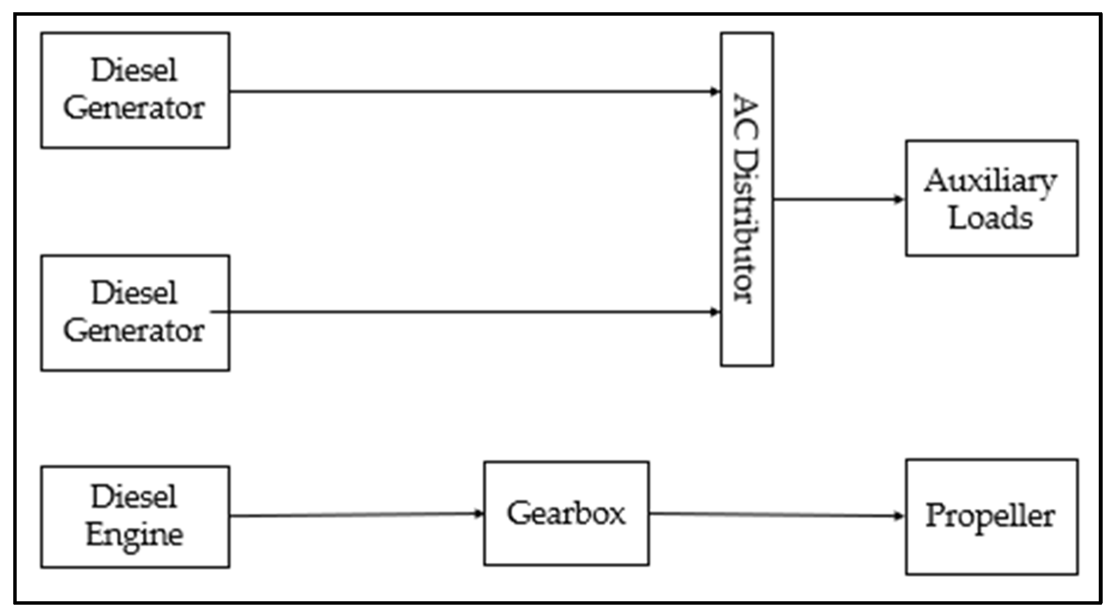
Figure 1. Simplified power flow for diesel–mechanical propulsion power system.
The power required for the other services of the vessels such as heating, ventilation and air conditioning (HVAC), as well as lighting will draw power from an auxiliary engine connected to an alternating current (AC) distributor. The main and auxiliary engines are fuelled by marine diesel oil (MDO)/heavy fuel oil (HFO). However, many ships’ systems are not able to handle the heavy residual from HFO, thereby these fuels are blended to produce fuel oil that is more suitable for use in ships, known as intermediate fuel oil (IFO). IFO is used to improve the viscosity and density of vanadium content, carbon content, and other characteristics of HFO [4]. The use of IFO generates a lower cost as compared to utilising a better-grade fuel oil for the system, such as very low-sulfur fuel oil with a maximum sulfur emission of 0.5% or ultra-low-sulfur fuel oil with a maximum sulfur emission of 0.1%.
Relevant studies on the carbon emissions and the cost function of the diesel–mechanical propulsion system can be found in [9], where a comparison study was conducted on the life cycle assessment of a diesel engine-powered ship to a battery-powered ship. The results showed that diesel engine-powered ships emit 56% more CO2 equivalent per nautical mile (CO2-eq/nm) as compared to their battery-powered counterparts. Another life cycle assessment study by Wang et al. [10] comparing tugboats with different configurations of propulsion systems was conducted to investigate the optimal system with the lowest emission, cost, and hazard impacts. Three medium engines, each rated at 1062 kW, were found to consume the least fuel oil at 24,680 tonnes equivalent to the cost of 15.5 million Euros as compared to 25,360 tonnes of a conventional two large engine configurations each rated at 1518 kW. Other means to reduce emissions and fuel consumption could be achieved by reducing the operating horsepower. However, lowering the horsepower may not be able to fulfil the service speed or bollard pull requirement [5].
The use of scrubbers is recommended for the removal of sulfur emissions of more than 95% at all engine loads, however, scrubbers are ineffective for reducing the emission of NOx and CO2, where a lower emission to higher engine load trend was observed [11]. By using exhaust gas recirculation, NOx emission could be reduced by up to 76%, however, it does not reduce CO2 emissions, due to the increase in engine temperature and dilution effects [12]. It is to note that the dilution effects are due to the results of the dilution of oxygen concentration. This thus increases the CO2 emissions as more exhaust gas is recirculated into the cylinder, thereby causing more oxygen to be displaced.
Benefits and Challenges of Diesel–Mechanical Propulsion
The greatest advantage of using this system, is the direct mechanical connection between the main engine to the propeller, resulting in minimal transmission losses [6]. The purchase cost of mechanical propulsion is cheaper than other systems due to its simplicity. Mechanical diesel propulsion operates most efficiently at 80–100% of the designed speed [13]. Ideally, vessels operating with limited operating profiles such as cargo ship travelling at single cruising speed benefits from diesel–mechanical propulsion due to the simplicity of the configuration and least dynamic engine loading.
The disadvantages of the system are poor fuel efficiency, high emissions when sailing at speed below 70% of top speed and fuel consumption significantly increases when rated power is below 50% [13]. A simple diesel–mechanical propulsion system provides no fallback plan, thereby failure of any components along the drive train results in loss of propulsion. The energy management of the engine is simple because it requires both systems to operate simultaneously, regardless of the power required. The dynamic loading also leads to an increase in the maintenance required for the engine. This could be overcome by the addition of an appropriate control strategy and alternatively using a controllable pitch propeller that can result in a reduction in the need for maintenance and improvement in manoeuvrability [14].
2.2. Electrical Propulsion System
The movement towards electrical propulsion has dated back as early as the 1990s [15] for cruise ships and naval vessels. Electrical propulsions are known to be more efficient in low-speed conditions, and it introduces conversion losses from 5–15% propulsion power due to the additional electrical components such as generators, power converters, transformers, and electric motors. Today electrical propulsion systems in vessels are crucial specifically for vessels operating in emission control areas (ECAs), as a significant amount of carbon emission could be effectively mitigated. The market in electrical propulsion ships for North America (blue), Europe (turquoise), Asia Pacific (green), and the rest of the world (yellow) is expected to increase over the next few years and grow by approximately USD 11.5 billion between 2021 and 2030 as shown in Figure 2 below [16].
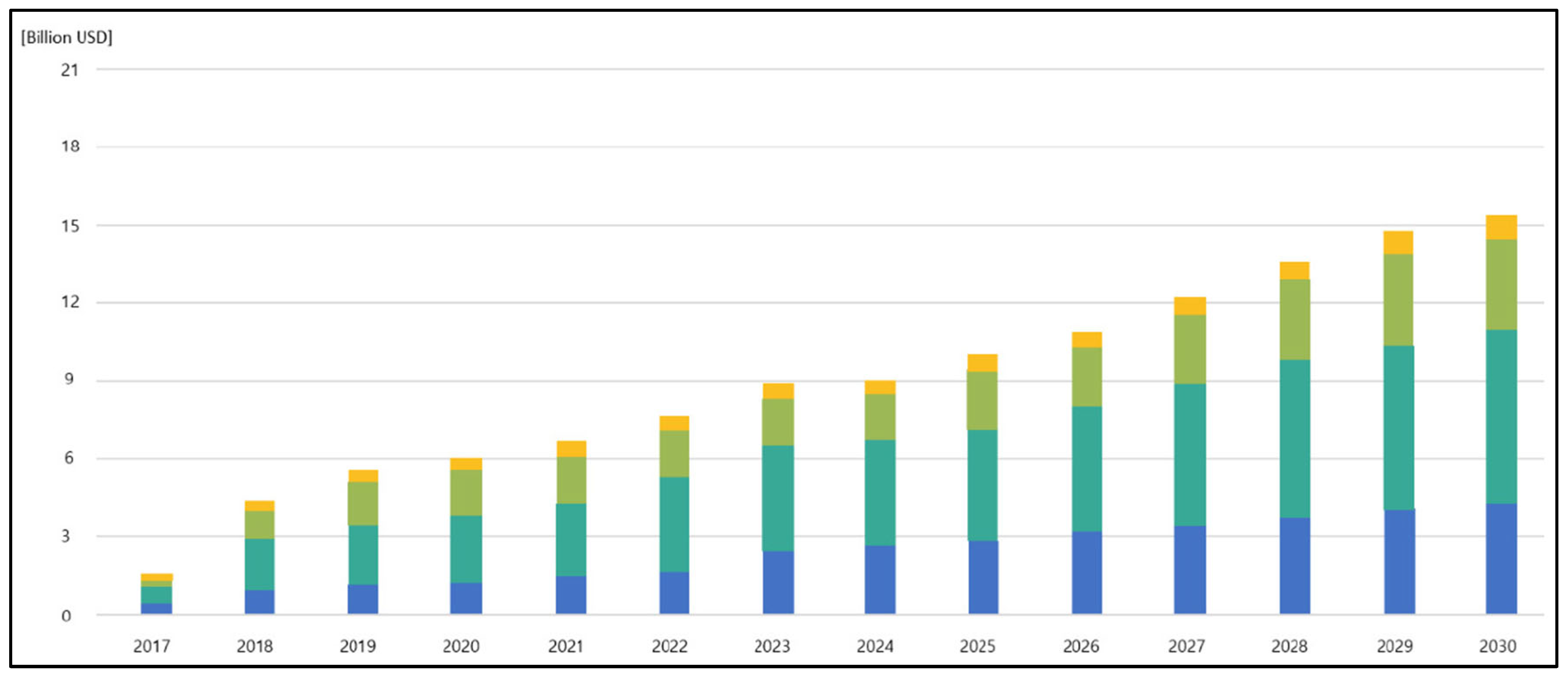
Figure 2. Market increase in electrical propulsion ships [16].
A direct current (DC) distribution is selected over an alternating current (AC) distribution because conversion between the transformer and main switchboards is eliminated, resulting in a smaller equipment footprint with up to 25% of the electrical component weight reduced for a platform supply vessel [17]. A standard DC distribution electric propulsion power system is shown in Figure 3. Several generator sets (Gensets) feed a fixed-frequency high voltage towards the electrical bus selector through an AC/DC rectifier to convert AC power from the Gensets to DC. The bus then feeds through a transformer and frequency converter to control the shaft speed and the required electrical power to the electric propulsion motor drive. Frequency converters may include both an AC–DC rectifier and a DC–AC inverter. This enables the electrical energy to be delivered and returned to the bus. DC electrical power from the bus selector feeds through the transformer and inverter to provide AC electrical power to other services and hotel loads. Another benefit of using DC over an AC distribution system is the redundancy for synchronisation. Synchronisation is required for parallel power sources for frequency, voltage, and phase to be the same before connecting to the power system. However, in a DC system, the phase and frequency do not need to be the same since the AC–DC rectifier produces a faster power generation response time [18].
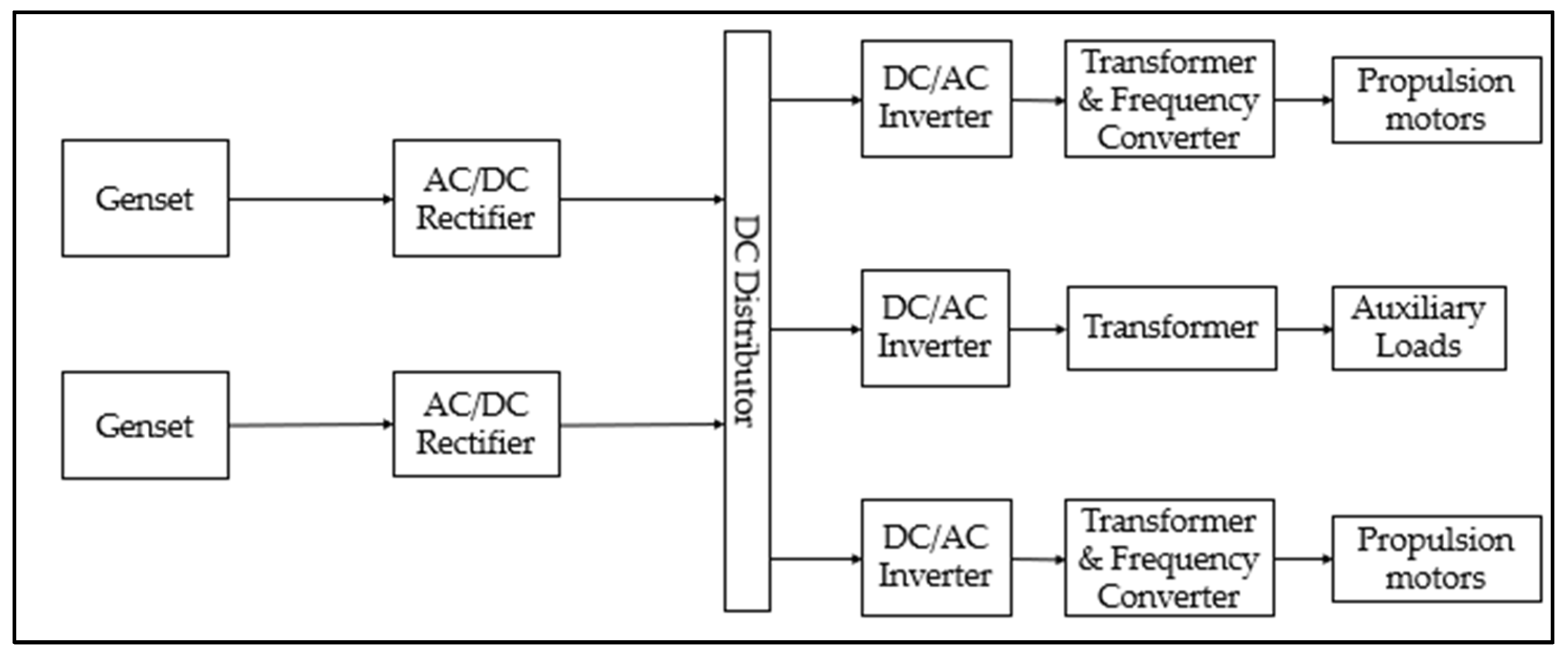
Figure 3. Simplified power flow of hybrid fully electric vessel power system.
AC electricity is used to distribute lighting and hotel loads because the load uses a constant frequency and low voltage [19]. As for propulsion, an AC–DC rectifier is used to generate DC power because the coupling between network frequency and engine speed is removed allowing a varied speed operation. This results in a 60–100% improvement in fuel efficiency due to the enhancement in the engine’s combustion process [20]. The freedom to control each power utilised in the propulsion system opens the opportunity to optimise fuel consumption and also reduces the maintenance load since the engine can be switched off when not required. The propulsion transformer is required to reduce the total harmonic distortion (THD) level to comply with the classification’s requirement [21].
Alternatively, instead of using Gensets, DC distribution supports the integration of energy storage such as batteries and renewable energy sources for more fuel savings and reduces life cycle and maintenance costs such as by the use of fuel cells. Batteries such as lithium-ion and nickel–cadmium for their rechargeable properties; however, lithium-ion batteries are more commonly found in fully electric power systems today due to their higher energy density and developments. An overview of fuel cells for maritime applications has been covered extensively by van Biert et al. [22]. Fuel cell research now focuses on renewable resources such as hydrogen, methanol, and LNG [23], which will be covered later in this section.
Benefits and Challenges of Electric Propulsion
The benefits of DC distribution electric propulsion systems have been described above. In summary, the benefits of using fully electric propulsion are as follows:
- lower transmission losses
- reduction in weight and space occupied in a ship
- improve propulsion efficiency and reduction in fuel and emissions
- simpler configuration of generators
- able to implement other energy storage
The electric propulsion system is usually complemented by a power management system (PMS) to optimise the distribution of loads. This is because an incorrect power supply and demand can result in the shutdown of the electrical system since power sources are connected to the same electrical network. Aside from that, PMS can be used to monitor the load and power available to trigger when to start and stop the Gensets. With the several conversions in the power stages, an increase in losses in its specific fuel consumption at the top speed of the ship occurs to the electrical propulsion [13].
However, the development of an optimised PMS to achieve the diverse operation load profile and the hotel load is challenging as it depends on many parameters such as fuel consumption, power, and engine RPM, which have to be obtained from sensors and are usually not readily available. An addition of a control strategy for the electrical network is required to maintain the voltage and frequency stability of the system, load distribution among the Gensets, and blackout preventions [24]. Although electric propulsion promises a reduction in fuel consumption and emissions, operating the Gensets to achieve higher propulsion requirements, for specific tugging operations or strategic manoeuvring, leads to poor fuel consumption and higher emissions.
2.3. Hybrid Propulsion System
Most ocean-going marine vessels such as cruises, ferries, and offshore support vessels (pipe-laying vessels) and warships use diesel–electric propulsion. An estimated fuel saving of 17% [25] could be achieved by using diesel–electric as compared to using diesel–mechanical propulsion. Hybrid propulsion with effective control strategies can reduce fuel consumption and emission by 10% to 35% [13]. This text covers two different types of hybrid diesel propulsion systems, i.e., diesel–electric powered by Gensets and diesel–electric powered by battery.
Diesel–electric powered by Gensets, as shown in Figure 4a, consists of a direct mechanical drive such as a diesel engine to provide high speeds connecting through a gearbox and to the propeller. Additionally, an electric motor coupled with the same gearbox or directly to the propeller could be used to provide propulsion for lower speeds and avoid overloading the main engine. Similarly, the motor acts as a generator for electric loads to other ship components. With the diesel engine, the system can produce power from either the electric generator or the Gensets. Ideally, a system of such complexity requires a rule-based control to determine the capacity required.
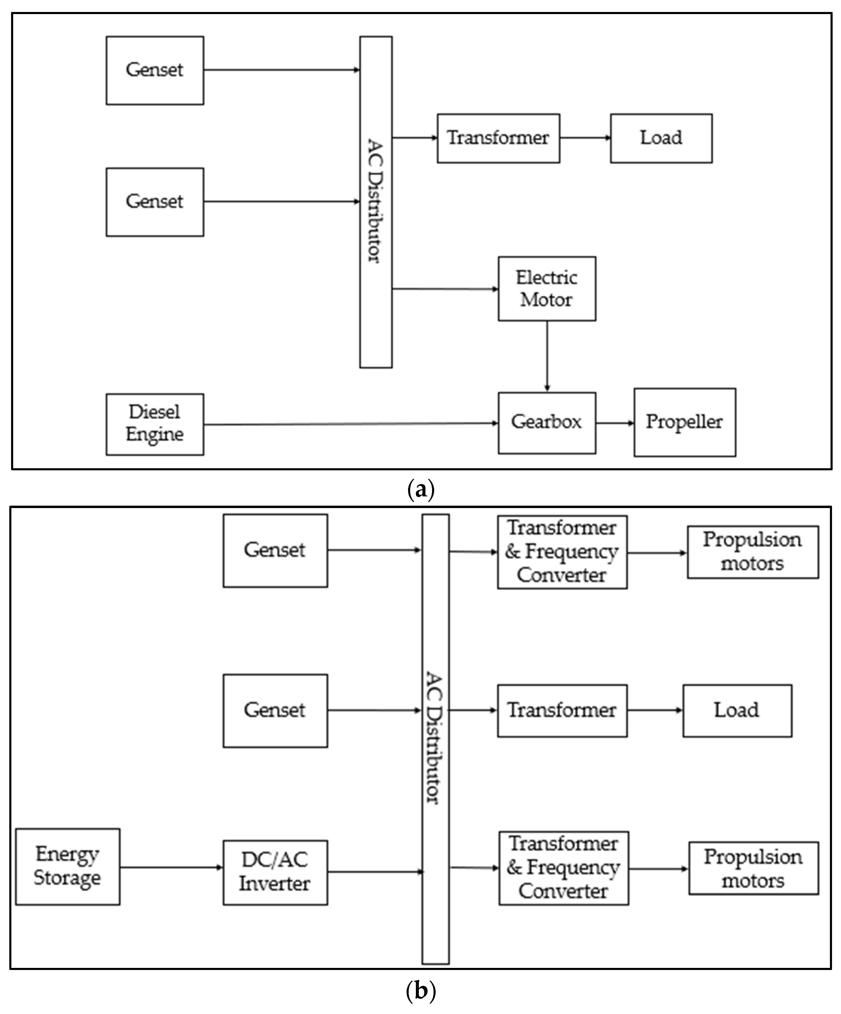
Figure 4. (a) Hybrid diesel with Gensets propulsion system; (b) Hybrid diesel with battery propulsion system.
Another variation of diesel–electric propulsion using battery or fuel cells is presented in Figure 4b. The system configuration is similar to Figure 4a but with an additional stored power supply such as a battery connected to the main distribution. The use of batteries as energy storage is adapted from the automotive industry, but the energy storage used in the automotive industry focuses on storing brake energy instead of using the energy to run the engine more efficiently [26]. Therefore, the energy storage in the ship enables maximum energy efficiency to be achieved with the flexibility of combining and switching the power consumption between the diesel engine and the electric energy from the Gensets and battery, respectively. The motor coupled with the gearbox enables the option of using the electrical drive to propel the vessel for low-speed manoeuvring. This has a clear advantage if compared to a diesel–mechanical propulsion system, which requires the gearbox to slow down the vessel, because there may be risks in overloading the engine and adding up to more maintenance cost for the mechanical propulsion system. The use of fuel cells with diesel engines or gas turbines can achieve high efficiencies by using more energy-dense fuels [22]. The complex control strategies of the hybrid system are important with the increasing level of complexity in the load-sharing profiles; a summary of these control strategies will be discussed in the later section.
Benefits and Challenges of Hybrid Diesel Propulsion
Hybrid diesel propulsion combines the benefits of both the electrical and mechanical components highlighted previously. However, a well-designed control strategy is still required to optimise these benefits, allowing electrical energy to be transferred from mechanical components to the electric component and vice versa.
Diesel–electrical propulsion has advantages in its ease of maintenance since electrical compliances occupy a smaller footprint as compared to mechanical components and allow for more flexibility in the positioning of the thrusters or any other mechanical equipment. The number of Gensets to operate can be controlled based on the power demand to improve fuel efficiency and engine loading. This then allows the diesel–electrical propulsion to provide a redundancy measure, where the other generators will be able to provide the necessary power load requirements in case of an engine failure [24]. The batteries installed onboard the vessel enable load levelling between the power fluctuation that occurs when vessel speed increases, thus leading to a more efficient operation, a method known as the peak shaving strategy. The peak shaving strategy from the battery, which is a method for the battery to deliver power during times when high power is required for a smoother operation and recharge when less power is required, can allow the engine to run more efficiently [27]. The energy storage can be recharged with the “charge-discharge mode” when the engine is operating with lesser fuel consumption to reduce emissions and save fuel [28]. Shore power can also be used to charge the batteries and as an alternative power source when ships are docked. The batteries can also act as a backup if a power failure or diesel generator malfunction occurs. This would ensure a continuous supply of electricity without disruption.
There are, however, some challenges of a hybrid propulsion system in the charging and discharging of the battery. A control strategy has to be designed and adopted to maximise the reduction in fuel consumption and carbon emissions. The control strategy selected should be able to dynamically optimise the load of the battery and engine.
3. Control Strategies
Control strategies are required in any electrical propulsion with an AC or DC distribution system. A comparison of AC and DC distribution control strategies is shown in Table 1, both systems with droop control as the most promising primary control strategy when compared to heuristic control or equivalent consumption minimization strategy in which the droop control demonstrates a reduction in fuel consumption of 5–10% [13]. Speed droop control and voltage droop control are the types of droop control available in the system; each operates in a similar methodology but with different inputs.
Table 1. Comparison of AC and DC distribution control.
| Comparison | AC Distribution System | DC Distribution System |
|---|---|---|
| Control Strategy |
|
|
| Advantages |
|
|
| Disadvantages |
|
|
Droop control is important to maintain the stability of an AC distribution network with two or more Gensets connected. On the other hand, speed droop controls the load sharing of power between active Gensets in parallel. It is used in the engine governor to control the engine speed, with the governor increasing the fuel to bring the engine speed back to the original speed. However, an overshoot in engine speed may occur due to inertia and power lag, hence the governor helps to respond by providing less fuel to reduce the engine speed. In layman’s terms, the droop control controls the increase in governor speed when the load decreases and vice versa. The amount of droop can be calculated based on Equation (1) [24]. Ideally, the recommended droop is to be set between 3% to 5% [29].
where no load speed is the speed of the generator when there is no power going through the generator and full load rated speed is the speed at maximum power. Generally, an increase in load will result in a decrease in the frequency speed of the generator. Similarly, a voltage droop control is used to control the load-sharing power between simultaneous active generators in parallel where an automatic voltage regular in the generator controls the output voltage of the Genset. The formulation to obtain the voltage droop is given in Equation (2), which is similar to Equation (1) but with speed replaced with voltage, where no load voltage represents the highest allowable load value of the voltage for the generator at the current nearing zero. The load will be the lowest with a higher current at full load-rated voltage.
4. Renewable Energy Sources
The DC distribution in hybrid propulsion could be designed to integrate with other sources of renewable energy fuels, such as hydrogen and liquified natural gas (LNG). Figure 5 shows the system power flow configuration of a hybrid propulsion system with LNG engines. When it comes to system modelling, a gas turbine model (GAST) is commonly used for dynamic models of power system components in simulation programs to simulate the power system behaviours of the gas engine, which was once Western Electricity Coordinating Council (WECC) compliant [30][31]. GAST models are used to simplify the gas engine process; however, the temperature control loop will be inactive as it leads to operational inaccuracy [32]. Since 2001, a more accurate model such as GGOV1 has superseded the GAST model. Similar to the hybrid propulsion system, a well-designed control strategy is required to optimise the load distribution and fuel consumption.
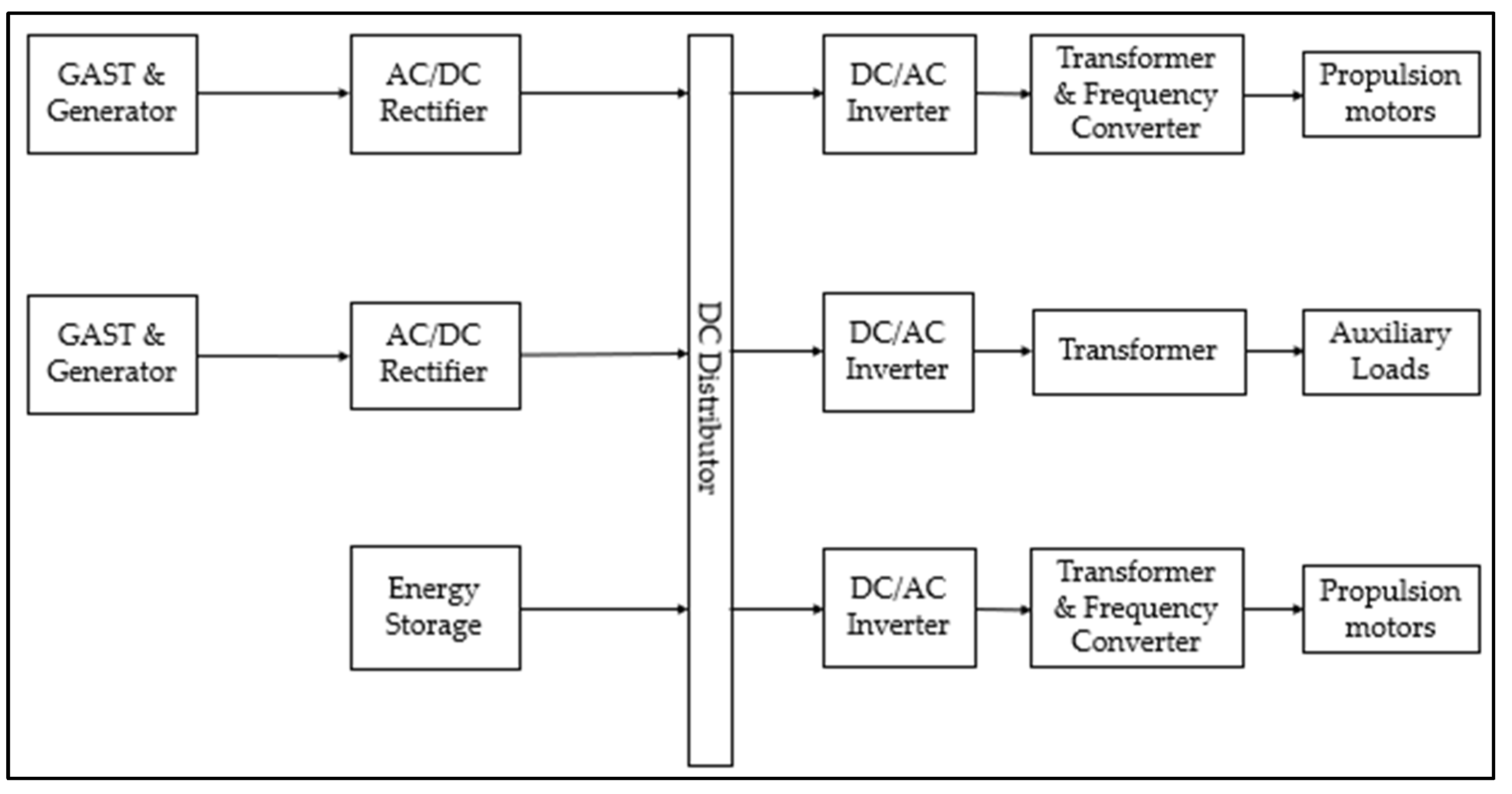
Figure 5. Simplified power flow of hybrid LNG–electric vessel power systems.
5. Digital Twin
The development of a system engineering model, besides allowing the monitoring of the ship’s performance during the design stage, could also be used in monitoring the behaviour of the ship during the operation stage. By collecting operational data from sensors installed onboard the ship, the data could be fed continuously in real time to the system engineering model to improve the model prediction. Such a model, known as the digital twin, serves as a virtual representation of a physical system that is updated through the exchange of information between physical and virtual systems [33]. The digital twin in the marine industry has received increasing attention due to the evolving need for digitalisation in the industry. It is capable of acquiring, managing and analysing the vessel’s required specifications to continuously update the status of the vessel in terms of propulsion performance or fatigue damage. A digital twin could also be used for the remote monitoring of the vessel’s performance or in predictive maintenance to detect anomalies and possible defects in system operations. In the predictive maintenance approach, maintenance is only executed when warranted, and this promises cost savings over time-based preventive maintenance where ships have to be called to dock at a fixed interval of time (usually in 3 to 5 years). The implementation of the digital twin is, however, costly, as various sensors have to be installed onboard ships. Additionally, the transmission of data from the sea to the shore and vice versa and the troubleshooting of sensors are challenging, especially when the vessels are operating in remote areas.
According to Fonseca and Gaspar [34], digital twins in ships can be divided into two different groups, i.e., the first group is decision support for ship operations, focusing on the in-condition monitoring and calibration of system models based on real operational data, whereas the second group is on the use of digitals twin for system integration testing and personnel training. Several studies have been conducted on the first group; e.g., Coraddu et al. [35] used a digital twin to estimate the speed loss of a vessel due to fouling where the digital twin system is updated with data captured on the vessel and in return, used to provide feedback on the estimated speed losses. Additionally, Danielsen-Haces [36] used a digital twin of autonomous vessels for the condition monitoring and calibration of the propulsion system simulation model based on operational data. For the second group, Tofte et al. [37] used a digital twin as an emulation of the control system, where a detailed simulation model of the system is created to use for hardware testing and operational training. The digital twin system could be integrated with a ship resistance and hydrodynamics model as well as vessel routing information that would provide input on the required propulsion power needed by the marine system. This, together with the ship manoeuvring performance, would help the EMS and PMS to best optimise the load distribution of the engine.
The digital twin has its own risks and challenges, such that in some cases, it may suffer from reliability issues with the data collected from the sensors, failure in the system modelling, and improper data processing [38]. Therefore, the digital twin is only suitable for some selective scenarios, as they may not be able to predict operation scenario cases that could lead to accidents. Nevertheless, being a relatively new topic in the marine industry, there has been a lot of progress, but more work is necessary.
References
- IRENA. Renewable Energy Options for Shipping. 2015. Available online: https://www.irena.org/-/media/Files/IRENA/Agency/Publication/2015/IRENA_Tech_Brief_RE_for-Shipping_2015.pdf (accessed on 19 May 2022).
- Chan, R.R.; Chua, L.; Tjahjowidodo, T. Enabling Technologies for Sustainable All-Electric Hybrid Vessels (Invited Paper). In Proceedings of the IEEE International Conference on Sustainable Energy Technologies, ICSET, Hanoi, Vietnam, 14–16 November 2016; pp. 401–406.
- Prevention of Air Pollution from Ships. Available online: https://www.imo.org/en/OurWork/Environment/Pages/Air-Pollution.aspx (accessed on 19 May 2022).
- Nitonye, S. Numerical Analysis for the Design of the Fuel System of a Sea Going Tug Boat in the Niger Delta. World J. Eng. Res. Technol. WJERT 2017, 3, 161–177.
- Karaçay, Ö.E.; Özsoysal, O.A. Techno-Economic Investigation of Alternative Propulsion Systems for Tugboats. Energy Convers. Manag. X 2021, 12, 100140.
- Hansen, J.F. Modelling and Control of Marine Power Systems; IFAC: Trondheim, Norway, 2000.
- Syverud, T.H. Modeling and Control of a DC-Grid Hybrid Power System with Battery and Variable Speed Diesel Generators; NTNU: Trondheim, Norway, 2016.
- Skjong, E.; Volden, R.; Rødskar, E.; Molinas, M.; Johansen, T.A.; Cunningham, J. Past, Present, and Future Challenges of the Marine Vessel’s Electrical Power System. IEEE Trans. Transp. Electrif. 2016, 2, 522–537.
- Perčić, M.; Ančić, I.; Vladimir, N.; Luttenberger, L.R. Comparative Life Cycle Assessment of Battery- and Diesel Engine-Driven Ro-Ro Passenger Vessel. Pomor. Zb. 2020, 3, 343–357.
- Wang, H.; Zhou, P.; Liang, Y.; Jeong, B.; Mesbahi, A. Optimization of Tugboat Propulsion System Configurations: A Holistic Life Cycle Assessment Case Study. J. Clean. Prod. 2020, 259, 120903.
- Yang, J.; Johnson, K.C.; Wayne Miller, J.; Durbin, T.D.; Jiang, Y.; Karavalakis, G.; Cocker III, D.R. Marine Scrubber Efficiency and NOx Emissions from Large Ocean Going Vessels. In Proceedings of the 2017 International Emissions Inventory Conference, Baltimore, MD, USA, 14–17 August 2017.
- Wang, Z.; Zhou, S.; Feng, Y.; Zhu, Y. Research of NOx Reduction on a Low-Speed Two-Stroke Marine Diesel Engine by Using EGR (Exhaust Gas Recirculation)–CB (Cylinder Bypass) and EGB (Exhaust Gas Bypass). Int. J. Hydrogen Energy 2017, 42, 19337–19345.
- Geertsma, R.D.; Negenborn, R.R.; Visser, K.; Hopman, J.J. Design and Control of Hybrid Power and Propulsion Systems for Smart Ships: A Review of Developments. Appl. Energy 2017, 194, 30–54.
- Stapersma, D.; Woud, H. Matching Propulsion Engine with Propulsor. J. Mar. Eng. Technol. 2014, 4, 25–32.
- Moreno, V.M. Future Trends in Electric Propulsion Systems for Commercial Vessels. J. Marit. Res. 2007, 4, 81–100.
- Market Research. Electric Ship Market by Type (Fully Electric, Hybrid), System, Mode of Operation (Manned, Remotely Operated, Autonomous), Ship Type (Commercial, Defense), Power, Range, Tonnage, End Use (Linefit and Retrofit), and Region—Global Forecast to 2030. Available online: https://www.marketresearch.com/MarketsandMarkets-v3719/Electric-Ship-Type-Fully-Hybrid-30200689/ (accessed on 19 May 2022).
- Hansen, J.-F.; Lindtjoern, J.O.; Myklebust, T.A.; Vanska, K. Onboard DC Grid: The Newest Design for Marine Power and Propulsion Systems. ABB Rev. 2012, 2, 29–33.
- Prenc, R.; Cuculić, A.; Baumgartner, I. Advantages of Using a DC Power System on Board Ship. Pomor. Zb. 2016, 52, 83–97.
- Kim, S.; Jeon, H. Comparative Analysis on AC and DC Distribution Systems for Electric Propulsion Ship. J. Mar. Sci. Eng. 2022, 10, 559.
- Heywood, J. Internal Combustion Engine Fundamentals, 2nd ed.; McGraw-Hill: New York, NY, USA, 2019; ISBN 9781260116113.
- Chua, L.W.Y.; Tjahjowidodo, T.; Lee, G.S.G.; Chan, R.; Adnanes, A.K. Equivalent Consumption Minimization Strategy for Hybrid All-Electric Tugboats to Optimize Fuel Savings. In Proceedings of the 2016 American Control Conference (ACC), Boston, MA, USA, 6–8 July 2016; American Automatic Control Council (AACC): San Diego, CA, USA, 2016; Volume 2016, pp. 6803–6808.
- van Biert, L.; Godjevac, M.; Visser, K.; Aravind, P.V. A Review of Fuel Cell Systems for Maritime Applications. J. Power Sources 2016, 327, 345–364.
- Leites, K.; Bauschulte, A.; Dragon, M.; Krummrich, S.; Nehter, P. Design of Different Diesel Based Fuel Cell Systems for Seagoing Vessels and Their Evaluation. ECS Trans. 2012, 42, 49–58.
- Chua, L.W.Y. A Strategy for Power Management of Electric Hybrid Marine Power Systems; Nanyang Technological University: Singapore, 2019.
- Adnanes, A.K. Maritime Electrical Installations and Diesel Electric Propulsion; ABB: Oslo, Norway, 2003.
- Feng, J. Brake Energy Recovery System for Electric Vehicle. Int. J. Ambient Energy 2019, 43, 942–945.
- Dedes, E.K.; Hudson, D.A.; Turnock, S.R. Assessing the Potential of Hybrid Energy Technology to Reduce Exhaust Emissions from Global Shipping. Energy Policy 2012, 40, 204–218.
- Zahedi, B.; Nebb, O.C.; Norum, L.E. An Isolated Bidirectional Converter Modeling for Hybrid Electric Ship Simulations. In Proceedings of the 2012 IEEE Transportation Electrification Conference and Expo (ITEC), Dearborn, MI, USA, 18–20 June 2012; IEEE: Piscataway, NJ, USA, 2012; pp. 1–6.
- Woodward. Governing Fundamentals and Power Management. Manual. 2011, p. 26260. Available online: https://www.pbm.hr/media/1101/woodward-governing-fundamentals.pdf (accessed on 19 May 2022).
- Yee, S.K.; Milanović, J.V.; Hughes, F.M. Overview and Comparative Analysis of Gas Turbine Models for System Stability Studies. IEEE Trans. Power Syst. 2008, 23, 108–118.
- Nagpal, M.; Moshref, A.; Morison, G.K.; Kundur, P. Experience with Testing and Modeling of Gas Turbines. Proc. IEEE Power Eng. Soc. Transm. Distrib. Conf. 2001, 2, 652–656.
- Mahat, P.; Chen, Z.; Bak-Jensen, B. Gas Turbine Control for Islanding Operation of Distribution Systems. In Proceedings of the 2009 IEEE Power & Energy Society General Meeting, Calgary, AB, Canada, 26–30 July 2009; IEEE: Piscataway, NJ, USA, 2009; pp. 1–7.
- VanDerHorn, E.; Mahadevan, S. Digital Twin: Generalization, Characterization and Implementation. Decis. Support Syst. 2021, 145, 113524.
- Fonseca, Í.A.; Gaspar, H.M. Challenges When Creating a Cohesive Digital Twin Ship: A Data Modelling Perspective. Sh. Technol. Res. Schiffstechnik 2021, 68, 70–83.
- Coraddu, A.; Oneto, L.; Baldi, F.; Cipollini, F.; Atlar, M.; Savio, S. Data-Driven Ship Digital Twin for Estimating the Speed Loss Caused by the Marine Fouling. Ocean Eng. 2019, 186, 106063.
- Danielsen-Haces, A. Digital Twin Development—Condition Monitoring and Simulation Comparison for the ReVolt Autonomous Model Ship; NTNU: Trondheim, Norway, 2018.
- Tofte, B.L.; Vennemann, O.; Mitchell, F.; Millington, N.; McGuire, L. How Digital Technology and Standardisation Can Improve Offshore Operations? In Proceedings of the Offshore Technology Conference, Houston, TX, USA, 6–9 May 2019.
- Ibrion, M.; Paltrinieri, N.; Nejad, A.R. On Risk of Digital Twin Implementation in Marine Industry: Learning from Aviation Industry. J. Phys. Conf. Ser. 2019, 1357, 012009.
More
Information
Subjects:
Engineering, Marine
Contributors
MDPI registered users' name will be linked to their SciProfiles pages. To register with us, please refer to https://encyclopedia.pub/register
:
View Times:
4.2K
Revisions:
2 times
(View History)
Update Date:
06 Jan 2023
Table of Contents


Notice
You are not a member of the advisory board for this topic. If you want to update advisory board member profile, please contact office@encyclopedia.pub.
OK
Confirm
Only members of the Encyclopedia advisory board for this topic are allowed to note entries. Would you like to become an advisory board member of the Encyclopedia?
Yes
No
${ textCharacter }/${ maxCharacter }
Submit
Cancel
Back
Comments
${ item }
|
${ item.createdUser.fullName }
${ item.createdAt }
${ item.vote }
${ item.reply }
Delete
${ reply.createdUser.fullName }
${ reply.createdAt }
${ reply.vote }
Delete
There is no reply to this comment~
${ item.replyTextCharacter }/${ item.replyMaxCharacter }
Submit
Cancel
More
No more~
There is no comment~
${ textCharacter }/${ maxCharacter }
Submit
Cancel
${ selectedItem.replyTextCharacter }/${ selectedItem.replyMaxCharacter }
Submit
Cancel
Confirm
Are you sure to Delete?
Yes
No