Your browser does not fully support modern features. Please upgrade for a smoother experience.
Submitted Successfully!
 +1 credit
Thank you for your contribution! You can also upload a video entry or images related to this topic.
For video creation, please contact our Academic Video Service.
| Version | Summary | Created by | Modification | Content Size | Created at | Operation |
|---|---|---|---|---|---|---|
| 1 | Zhong qi Xie | -- | 3766 | 2022-11-24 02:59:56 | | | |
| 2 | Zhong qi Xie | + 76 word(s) | 3842 | 2022-11-24 03:29:21 | | | | |
| 3 | Rita Xu | -7 word(s) | 3835 | 2022-11-24 03:50:06 | | | | |
| 4 | Zhong qi Xie | -7 word(s) | 3835 | 2022-11-24 03:58:35 | | |
Video Upload Options
We provide professional Academic Video Service to translate complex research into visually appealing presentations. Would you like to try it?
Cite
If you have any further questions, please contact Encyclopedia Editorial Office.
Wang, Z.; Fang, Z.; Xie, Z.; Smith, D.E. Fiber Attrition and Micro-Voids. Encyclopedia. Available online: https://encyclopedia.pub/entry/36155 (accessed on 24 June 2026).
Wang Z, Fang Z, Xie Z, Smith DE. Fiber Attrition and Micro-Voids. Encyclopedia. Available at: https://encyclopedia.pub/entry/36155. Accessed June 24, 2026.
Wang, Zhaogui, Zhenyu Fang, Zhongqi Xie, Douglas E. Smith. "Fiber Attrition and Micro-Voids" Encyclopedia, https://encyclopedia.pub/entry/36155 (accessed June 24, 2026).
Wang, Z., Fang, Z., Xie, Z., & Smith, D.E. (2022, November 24). Fiber Attrition and Micro-Voids. In Encyclopedia. https://encyclopedia.pub/entry/36155
Wang, Zhaogui, et al. "Fiber Attrition and Micro-Voids." Encyclopedia. Web. 24 November, 2022.
Copy Citation
A discontinuous fiber-reinforced polymer composite (DFRPC) provides superior mechanical performances in material extrusion additive manufacturing (MEAM) parts, and thus promotes their implementations in engineering applications. The process-induced structural defects of DFRPCs increase the probability of pre-mature failures as the manufactured parts experience complicated external loads. The process-induced fiber length attrition and micro-voids formations in MEAM applications is provided. By gaining a clearer view of the correlations between the MEAM processing parameters, and tooling and the resulting microstructures of produced DFRPCs, it is expected to manufacture composites parts with more preferable mechanical properties via MEAM.
DFRPC
MEAM
fiber attrition
micro-voids
1. Introduction
Material extrusion additive manufacturing (MEAM), otherwise known as Fused Filament Fabrication (FFF), or Fused Deposition Modeling (FDMTM [1]) more commonly, offers the ability to rapidly build intricate structures at a low cost, and thus stands as a most popular manufacturing approach in modern automotive, aerospace, and other advanced industries [2]. Among several additive manufacturing techniques, MEAM stands out in terms of the range of applicable materials [3]. As the demand for lightweight, high-strength materials is continuously growing in aerospace and automotive industries, engineering applications of discontinuous fiber-reinforced polymer composites (DFRPCs) are becoming of interest. DFRPCs exhibit superior material stiffness and strength as compared to their virgin polymer alternatives [4]. They also reduce the thermal expansion behavior of the deposited material, and thus enhance the dimensional stability of MEAM-produced parts [5]. Meanwhile, DFRPCs can be more easily processed via MEAM systems as compared to their competitor, the continuous fiber-reinforced polymer composites (CFRPCs). To this end, DFRPCs are largely adopted in the recent-emerging large area extrusion deposition additive manufacturing (LAAM) technology as a convenient, low-cost, and efficient feedstock choice. LAAM is an MEAM-based approach, wherein a screw extruder is often involved with pelletized feedstock. A typical process of LAAM is to melt polymer composite pellets through the screw extruder, and to then deposit the molten materials onto a substrate in a relatively high flow rate (i.e., 2–10 kg/h for commercially available systems [6], and ~100 kg/h or higher for those mounted in research institutes, e.g., the super LAAM system in the University of Maine [7]). LAAM is extraordinarily useful in the rapid fabrication of parts and/or tooling in large-dimension (e.g., whole parts for full-size cars [8][9], naval applications [10][11][12][13], and large-dimension tooling [14][15]), as shown in Figure 1. In the particular COVID-19 context, it helps in rapidly building essential infrastructure for emergency medical purposes [16].

Figure 1. Widespread LAAM-produced composites' applications in different engineering fields.
As shown above, due to the benefits of MEAM in rapidly fabricating lightweight structures with high stiffness and strength-to-weight ratios, researchers see continuously increased applications employing MEAM-produced DFRCPs as machine tooling or end-use engineering parts [8][10][11][12][17][18]. Nevertheless, a universally applicable set of processing parameters for MEAM (especially for large-scale MEAM) has not been found. This is mainly due to the fact that the complex thermal–mechanical physics occurring during the MEAM process cannot be controlled perfectly (cf. Figure 2). As mentioned, a typical process of MEAM implies the extrusion of molten thermoplastic feedstock through a nozzle orifice, which is then deposited on a pre-heated material platform. The viscoelastic nature of the thermoplastic-based materials makes the molten material flow, and the subsequent solidification, inter-beads wetting, and bonding make it hard to control from one type of polymer to the other [19][20][21]. A first and inevitable cause is that MEAM is inherently employed to create structures with complex geometries [22][23], and thus the deposited bead layer thickness [24][25][26][27], building orientation [28][29][30][31][32], print toolpath [33][34][35], infill structures [36][37][38][39], density [40][41][42][43], and so forth may drastically vary from part to part. Hence, the studies focused on the optimization of the print structure in the form of a multi-parameter combination with objective optimization effects, even with the aid of some advanced technology (i.e., the artificial neural network [44][45][46]), while they mostly could only offer qualitative guidance [47][48][49][50]. Due to the layer-by-layer fashion of manufacturing, MEAM structures inherently exhibit anisotropic mechanical responses subjected to different directions of external loads [51][52], e.g., lower bending strength and stiffness can be seen in the direction of layer accumulation as compared to those along in-plane deposition directions [53]. Gao et al. [54] suggested that the weak interlayer bond interfaces are a main contributor for the MEAM parts to exhibit weak and anisotropic mechanical properties. Another standpoint is that inter-filaments voids introduced in the additive manufacturing process greatly contribute to anisotropy [55]. The explanation is that the porous structures or voids can affect the mechanical performances of MEAM parts [56], which are prone to be undermined [57][58][59]. When operating as a load-bearing component, an MEAM part fails much easier when the external load direction is perpendicular to the material deposition plane, since severe stress concentrations are more likely to occur nearby meso-voids among interlayers in such conditions, as compared to those where load direction is parallel to the material deposition direction [60]. In addition, the bond formation mechanisms for amorphous and semi-crystalline polymers are different, which leads to a different degree of material anisotropy (e.g., PLA parts at around 50%, and PA which are less anisotropic, on an order of 10% [54]). This implies another important feature of polymers in contributing to the material’s anisotropy, which is the flow-induced polymer crystallization [61]. Brenken et al. predicted the non-isothermal crystallization for a semi-crystalline fiber-filled PPS and the non-uniform crystallization of an MEAM part was attributed to an anisotropic material performance factor [62]. Thermoplastics feedstock applied in FFF often exhibits intensive viscoelastic behaviors, e.g., the extrudate swell occurs during the extrusion deposition process [63], which greatly affects the print resolution and thus leads to the formation of inter-beads voids [60]. Therefore, the layer-by-layer-formed meso-structure is often considered as an inherent cause for the material anisotropy of MEAM-printed parts. In order to address such issue, the prior literature provided insights by explaining the meso-structural formations of MEAM-produced parts [53][64].

Figure 2. MEAM printing parameters that lead to weak meso-structure.
As discussed, the meso-structures of MEAM-produced thermoplastics are relatively weak, notably in the case of DFRPCs, wherein the fabricated structures exhibit more complex material properties owing to the inhomogeneous micro-structures formed by compounding discontinuous fibers and the polymer matrix [65]. As the DFRPC feedstock is extruded and deposited on a moving platform, velocity gradients within the melt orientate the suspended discontinuous fibers, and the final orientation pattern within the deposited beads directly affects the material properties of the solidified products. The narrow-gap shear-dominated flow in the nozzle die orifice induces a highly aligned fiber orientation along the direction of material loading [66], and thus leads to anisotropic material behaviors in macro-view. The prior literature tested the material properties of MEAM-made parts, wherein the deposited composites' elastic moduli [67], thermal conductivity [68], and thermal expansion coefficient [5] were found to exhibit strongly anisotropic behaviors. Numerical studies were carried out in regarding the special behaviors of MEAM parts. Brenken et al. [69] performed a finite element simulation to study the thermal history of 50 wt.% CF/PPS in an MEAM process, wherein the anisotropic thermal conductivity of the short-fiber polymer composite was found. Compton et al. [70] simulated the time-dependent temperature contour of a LAAM-produced carbon fiber-filled ABS (CF/ABS) part through the finite element method, wherein an anisotropic thermal conductivity was assumed. Their solution implied that higher thermal conductivity is shown to be detrimental to the success of the build. Hoskins et al. [71] modelled the coefficient of thermal expansion of the deposited beads using a non-homogenized modeling approach, wherein the locally measured fiber orientation states were applied. The simulated results of the residual thermal stress within a printed cuboidal part of the CF/ABS were shown to be in line with the experimental scanning results [72]. Among various MEAM structures, the sandwich beam is one of the preferrable structures by virtue of its ability to combine the advantages of different materials, wherein the DFRPCs' properties can be better exploited. Li and Wang [73] tested the sandwich composites wherein a carbon fiber-reinforced polymer (CFRP) was introduced as face sheets, as well as three types of inclusions. Compared to the conventional honeycomb-shaped inclusion, the sandwich beams embedded with a re-entrant honeycomb presented better energy absorption abilities. Hou et al. [74] compared three types of lattice composites inclusion, wherein CFRPs were used as face sheets, and wherein three kinds of core topologies were applicable for different impact-loading circumstances. Hassan et al. [75] proposed a finite element model to investigate the effect of different parameters of inclusion on the sandwich beams' mechanical behavior. Essassi et al. [76] analyzed the fatigue behavior of the sandwich composites with four kinds of core densities, which possessed different stress ratios. It was found that a sandwich structure with a low core density can withstand a low maximum load, while its fatigue life is longer, which means that there must be a compromise between load bearing and fatigue life.
2. Fiber Length Attrition
Fiber length is one of the most crucial factors that determines the properties' enhancement of reinforced polymers. In desktop-size MEAM processes (e.g., FFF), the fiber length stays stable from the filament feedstock to the deposited parts. As shown from Jiang and Smith [77] (cf. Figure 3), researchers see that the fiber length distributions in filament and printed conditions exhibit subtle differences for all examined filled polymers (including ABS, PLA, PETG, and AmphoraTM). Although the FFF extrusion and deposition processes yield little fiber length attrition, the fraction of filled fibers plays an important factor contributing to fiber length attritions. Tekinalp et al. [66] measured the fiber length distributions of CF/ABS with different weight fractions prepared via compression molding (CM) and FDM. As the results show in Figure 4, it is seen that the averaged fiber length values reduced significantly with an increased fiber weight fraction, wherein the trend of reduction in the FDM samples was much higher than that of the CM samples. This indicated that the fraction of filled polymer feedstock applied in FDM (or say, filament-based MEAM) may have had an effective fraction limitation, i.e., a higher filled fraction may suffer significant fiber length attrition and result in under-expected property improvement in the produced composites. This phenomenon was also reported by Ning et al., wherein the tensile properties and associated micro-structural fiber length attritions of FDM-produced CF/ABS samples were studied [78]. Therefore, researchers can see that the commercially available fiber composites for filament-based MEAM systems are often filled with ~10 wt.% fiber contents, balancing the cost and effectiveness of property enhancements.

Figure 3. Fiber length distributions plots for each CFF material filament [77].

Figure 4. Fiber length distributions (A) compression-molded, (B) FDM-printed, and (C) weight average fiber lengths of dog bone samples [66].
Researchers note that the nozzle diameter of a desktop MEAM system is often 400 μm, and thus it is not surprising that longer fibers would not survive through the extrusion deposition process to the final printed parts. Nevertheless, the large-scale MEAM systems with screw-extruders employed are often equipped with nozzles in much larger diameters (e.g., in the magnitude of ~1 mm, or even ~10 mm). The upgraded extrusion die allows for the longer fibers to survive, and then a higher increment in material properties in the deposited composites is expected. Nevertheless, the revolute material feeding system may yield considerable geometry loss for the reinforced discontinuous fibers. Berzin et al. performed fiber geometry measurements along the flow direction of a twin-screw extruder (cf. Figure 5 and Figure 6), and both the length and diameter exhibited more than 100% reductions at the end of the screw, as compared to their starting dimensions [79]. Hausnerova et al. showed that the high shear stress generated during the screw rotation has a direct effect on reducing the length of the reinforced fibers, and the composites with increasing fiber volume fractions exhibited a decreasing averaged fiber length after screw processing [80]. Aigner et al. employed the X-ray computed tomography approach in measuring the fiber breakage of a glass fiber polymer composite processed through a single screw extruder, wherein the maximum fiber length of the extruded composites was reduced by ~50%, as compared to data provided by the manufacturer [81]. Goris found that the melting temperature was also attributed to the degradation of fiber length of long fiber-reinforced composites in an injection molding application [82]. Similar studies carried out by Zhuang et al. [83] and Bailey and Kraft [84] indicated that the processing parameters' residence time and molding pressure were contributors to fiber length loss. Bayush et al. measured the fiber length distribution of screw-extruder-processed hemp fiber-reinforced polypropylenes and the mechanical and dynamic properties of the compound were tested. The results indicated that maintaining a relatively larger averaged fiber length benefited the mechanical performances of the natural fiber composites [85]. Gamon et al. [86] suggested that maintaining the fiber length in higher values enhanced the flexural behavior of screw-extruded composites. Inoue et al. [87] studied the effect of the screw design on the fiber breakage and dispersion and reported that the fiber length was a direct factor in determining the mechanical properties of the mixed composite. For this reason, researchers should not be surprised that discontinuous fiber composites experience fiber geometry loss during LAAM.

Figure 5. Scheme of the laboratory scale twin-screw extruder (Clextral BC21). Restrictive zones are in grey. Arrows indicate sampling locations [79].

Figure 6. Changes in length (A) and diameter (B) of 12 mm flax fibers along the screws (2 kg/h, 100 rpm). Lines are just to guide the eyes [79].
Duty et al. employed two different designs of the screw barrel in an LAAM system and elastic modulus along the print direction of the deposited 20 wt.% SGF/ABS (i.e., short glass fiber-filled ABS) exhibited a difference of 42% [67], implying that the screw design had an influence on the fiber length attrition and associated elastic properties of the deposited beads. Russell and Jack [88] and Wang et al. [89] separately measured the fiber length distributions of pellets and deposited beads of 13 wt.% CF/ABS that were used in LAAM applications. They continued by employing the fiber length distribution data in a homogenization approach for evaluating the elastic properties of short fiber composites, and the results suggested that the longer fibers led to higher tensile moduli [88][89]. Yeole et al. measured the fiber length distribution of 50 wt.% CF/PPS processed via a large-scale MEAM system [90], wherein a 10.16 mm-nozzle (diameter) was employed. The measured data of pellet feedstock and deposited beads are presented in Figure 7, where the fibers exhibited little length reduction in comparing the data between the pellets and the beads. The averaged fiber length, on the other hand, was above ~300 μm, which was higher than what researchers have normally seen in desktop-size systems produced (i.e., 50–100 μm). In addition, the fiber fraction of the feedstock reached 50 wt.%, which was also higher than FDM-used feedstock (e.g., Jiang ang Smith [77], Ning et al. [78]). The higher fiber length and fiber fraction obtained by the large-scale system indicate that large-scale MEAM systems are promising in producing composite structures with superior mechanical properties. Consequently, researchers need to note that higher length of fibers also reinforces the material anisotropy of MEAM-produced composites, and thus a trade-off may be needed in selecting proper filled polymer feedstock based on different application demands.

Figure 7. Probability distribution of fiber length: (A) pellets; (B) deposited beads [90].
In order to further understand the fiber length attrition behaviors, theoretical and numerical studies were conducted. Bereaux et al. [91] modelled the bending moments of a single fiber as it passed by the screw-generated shear flow, and the fiber length distribution resulted from the extruded composites was computed. They stated that the fiber fracture occurred when screw-applied shear stress exceeded the critical bending fiber length, which indicated the importance of the screw’s design in retaining the fiber length [91]. In the injection molding process of long fiber thermoplastics (LFTs), Phelps et al. [92] modeled the fiber breakage phenomenon by considering the fiber buckling effects. They correlated the fiber length attrition with the fiber orientation state, as shown in Figure 8, wherein the predicted results obtained by Phelps showed a good agreement with the corresponding experiments on glass-fiber/polypropylene LFTs molding [92]. Bechara et al. [93] recently presented a phenomenological constitutive model for the fiber breakage modeling of LFT molding parts based on rheological experiments on simple shear flows of the glass fiber-filled PP polymer (cf. Figure 9). The model was based on the beam theory, wherein the fiber–fiber interactions were considered together with the fiber volume fraction via a fitting parameter (i.e., phenomenological parameter). This model can be used to track the number-average and weight-average fiber length values during the injection molding process, which is practically useful. Nevertheless, the numerical models are limited to molding process applications. The MEAM extrusion deposition process takes place mainly under lower pressure and temperature conditions, as compared to typical molding processes, and thus the fiber buckling and associated breakage may exhibit differences. Researchers note that it is important to develop constitutive models to depict the fiber length reduction in MEAM applications, especially for the large-scale systems.

Figure 8. (A) Sphere of all possible fiber directions p, colored by the value of (D: pp) for the simple shear flow vx=γ˙z. Negative values (red to yellow colors) indicate orientations where the fiber is in compression. Points on the sphere are a sample of fiber orientations at steady state for this flow, calculated using the Folgar–Tucker model; (B) Fraction fi of fibers that have an orientation in which they can buckle, as a function of the buckling parameter Bi, for various steady-state orientations in simple shear flow.

Figure 9. Micro-CT slices of fiber dispersion for PPGF40 (40 wt.% glass fiber-filled PP polymer) exposed to a simple shear flow at 50 s−1 for different residence times. Of note, the fiber diameter is 14–24 μm, and the density of fibers is 2.56 g/cm3 [93].
3. Micro-Voids
While fiber reinforcements are expected to improve the material properties of MEAM-deposited composites as compared to the alternative virgin polymers, the MEAM-flow-induced variations of the fiber-related micro6structures (e.g., fiber orientation, fiber attrition, fiber migration, and/or imperfect fiber/matrix bonding) can result in a significant amount of micro-porosities within the produced composites. Al-Maharma et al. [94] conducted a critical review on the correlations between the micro-voids in the additively manufactured parts and their macro mechanical properties. These defects can potentially impact the fatigue strength, stiffness, mechanical strength, fracture toughness properties, and even corrosion resistance. Additionally, the existing micro-voids sometimes tend to concentrate the interfacial stresses, influencing the interlaminar bonding quality, resulting in the interfacial flaws, e.g., interfacial dislocation and delamination. Yu et al. [95] explored the contribution of printing-induced fiber alignment and voids coupled with the matrix to the anisotropic elastic modulus, assisted by computational tomography (CT). The relationship implied that the Young’s modulus, shear modulus, and Poisson’s ratio can be tailored by programming the printing direction. Kong et al. [96] studied the interfacial failure under the pure and mixed modes. The research showed that the interlaminar characteristics of different materials and fiber angles could be markedly different. Papon et al. [97] focused on overcoming such drawbacks by means of acid-based oxidation treatment and vacuum annealing, which remarkably increased crystallinity (~100%) and enhanced the fiber–matrix interfacial bonding. To this end, researchers consider the micro-void as a vital component to better understand the material properties of MEAM-produced composites. Chisena et al. [98] evaluated the fractions of porosity, fibers, and polymer matrix in MEAM-produced nylon composites via micro-CT scanning. They found that the printed beads near the heat-bed exhibited ×1.5 larger pores (i.e., >250 μm2) than those in the upper region of the printed sample (i.e., <100 μm2), which was considered as a result of the vertically formed large thermal gradients along the deposited beads (cf. Figure 10). Yeole et al. [90] explored the microstructural formations of 50 wt.% CF/PPS processed via molding processes and MEAM process. They found that the micro-voids of MEAM-printed beads were larger than those prepared via compression molding, as shown in Figure 11. Additionally, the highly aligned flow-direction fiber orientation was attributed to the generation of the micro porosities in the deposited beads. Somireddy et al. stated that the thicker layers also yielded more micro-voids in the deposited beads and thus led to more anisotropy in SCF parts [99]. Sommacal et al. [100] studied the micro-voids and related fiber alignment in filament-MEAM-produced PEEK material samples via micro-CT imaging. The results indicated that both the filament feedstock and the printed bead contained a significant amount of voids, and the printing process did not remove the voids originally presented in the filament. Kumar et al. [101] combined the large-scale MEAM and compression molding (CM) processes to reduce the micro-voids within raw MEAM-produced composites. Their results indicated that the combined AM–CM method effectively reduced ~50% of porosity volume fraction as compared to the raw MEAM-produced composites (cf. Figure 12). Tagscherer et al. [102] performed a fundamental study on the microstructural formation of large-scale MEAM-produced composite parts via X-CT imaging. Their results suggested that a higher layer thickness helped decreased the chance of micro-voids, and these micro pores were found in the core of a deposited bead rather than at the free surface boundary of the deposition flow.

Figure 10. Top, front, and side cross-sectional views and isometric view of CT of MEAM-produced SCF parts. Blue, orange, and green dotted lines and colors represent cross-sectional views of MEX layers and straight and curved raster lines. Red dotted boxes are ROIs (Regions Of Interests) that will be analyzed using a mixed skew-Gaussian distribution (MSGD). The XY view shows the intersection of a straight and curved raster with three ROIs: A—the straight raster, B—the curved raster, and C—the intersection zone. The XZ view shows the MEX layer stacking and the porosity distribution across the layer interface using ROI D with the porosity distribution determined in w x Δz areas along the Z-direction. The ZY view shows the side cross-section of the straight (ROI E) and curved (ROI F) regions [98].
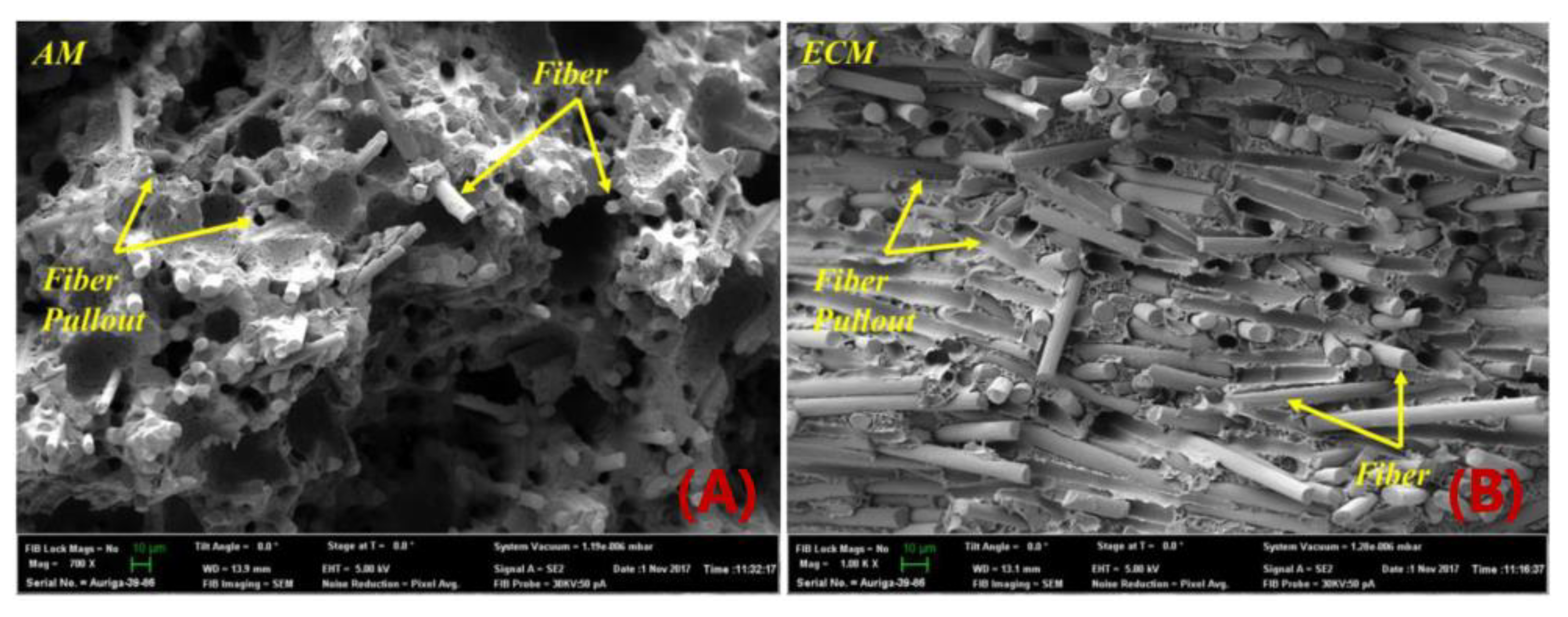
Figure 11. SEM micrographs of a fracture surface of tensile samples; (A) MEAM sample: Most of the fibers are aligned in printing direction, also contain voids; (B) Compression-molded sample: Fibers are well distributed in all directions [90].
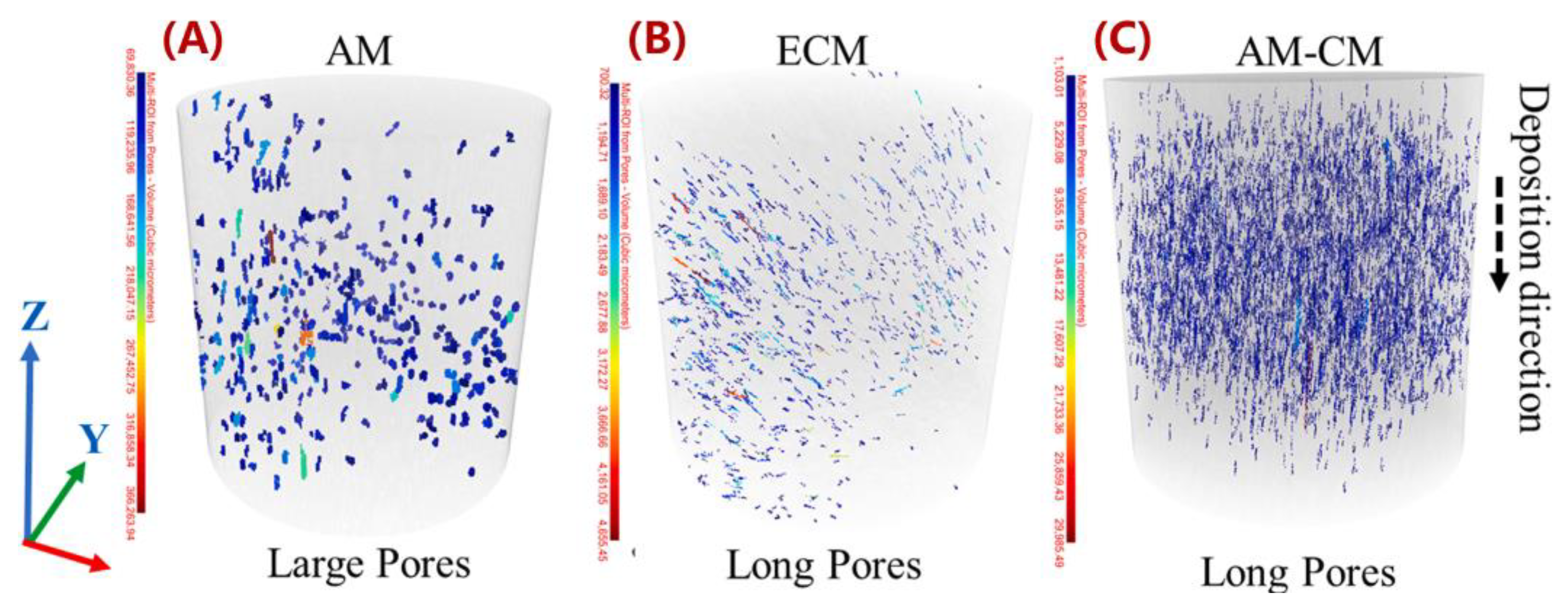
Figure 12. xCT for high aspect ratio pores along the fibers (A) AM, (B) ECM, and (C) AM–CM [101].
Thanks to the rapid development of the non-destructive tomographic methods (e.g., micro-CT scanning), researchers see studies analyzing the fiber-related micro-voids formulations in MEAM processes, including filament-based and pellet-based (i.e., large-scale system). On the contrary, the literature addressing the micro-voids' formation from numerical perspectives is scarce. Awenlimobor et al. explained the micro-void formation of the MEAM-produced composites by a finite element fiber suspension analysis [103], wherein the velocity gradients and the pressure distribution of a single fiber along a deposition flow streamline were presented. The pressure distribution of the fibers was considered as a direct factor determining the micro-voids' formation near the fibers (cf. Figure 13). They also plan to continue the study with 3D flow modeling and correlate the micro-voids with flow shear rate and other kinematics information. The numerical models and simulations depicting how micro-voids are formed during the MEAM process are still lacking. Nevertheless, the above experimental observations (e.g., [94][98][99]) suggest that the micro-voids within MEAM-produced composites yield significant impacts in reducing the mechanical performance of printed structures. Therefore, researchers see a high demand for numerical modeling works of micro-porosity analysis in MEAM flow studies.

Figure 13. Pressure Distribution around fiber surface: (A) γe=1; (B) γe=3; (C) γe=6. Of note, γe represents the fiber aspect ratio of an ellipsoidal fiber.
References
- FDM European Union Trademark Information. Available online: https://www.trademarkelite.com/europe/trademark/trademark-detail/011163524/FDM (accessed on 5 September 2022).
- Guo, N.; Leu, M.C. Additive manufacturing: Technology, applications and research needs. Front. Mech. Eng. 2013, 8, 215–243.
- Daminabo, S.C.; Goel, S.; Grammatikos, S.A.; Nezhad, H.Y.; Thakur, V.K. Fused deposition modeling-based additive manufacturing (3D printing): Techniques for polymer material systems. Mater. Today Chem. 2020, 16, 100248.
- Ismail, K.I.; Yap, T.C.; Ahmed, R. 3D-Printed Fiber-Reinforced Polymer Composites by Fused Deposition Modelling (FDM): Fiber Length and Fiber Implementation Techniques. Polymers 2022, 14, 4659.
- Love, L.J.; Kunc, V.; Rios, O.; Duty, C.E.; Elliott, A.M.; Post, B.K.; Smith, R.J.; Blue, C.A. The importance of carbon fiber to polymer additive manufacturing. J. Mater. Res. 2014, 29, 1893–1898.
- Brenken, B.; Barocio, E.; Favaloro, A.; Kunc, V.; Pipes, R.B. Fused filament fabrication of fiber-reinforced polymers: A review. Addit. Manuf. 2018, 21, 1–16.
- $20 Million Additive Manufacturing Initiative Connects Local Economies with National Lab, UMaine Resources. Available online: https://composites.umaine.edu/2019/05/02/new-20-million-additive-manufacturing-initiative-connects-local-economies-with-national-lab-umaine-resources/ (accessed on 30 May 2021).
- The Strati: World’s First 3D Printed Car Built in 44 Hours. Available online: https://fossbytes.com/strati-worlds-first-3d-printed-car-built-44-hours/ (accessed on 5 September 2022).
- Talagani, M.R.; DorMohammadi, S.; Dutton, R.; Godines, C.; Baid, H.; Abdi, F.; Kunc, V.; Compton, B.; Simunovic, S.; Duty, C.; et al. Numerical simulation of big area additive manufacturing (3D printing) of a full size car. Sampe J. 2015, 51, 27–36.
- LSAM Large Scale Additive Manufacturing Systems. Available online: https://www.advanced-machine-systems.co.uk/product/lsam-systems/ (accessed on 5 September 2022).
- This 3D-Printed Sub Could Be the Future of Undersea Warfare. Available online: https://www.popularmechanics.com/technology/robots/a34826410/dive-technology-3d-printed-submarine/ (accessed on 5 September 2022).
- Nieto, D.M.; López, V.C.; Molina, S.I. Large-format polymeric pellet-based additive manufacturing for the naval industry. Addit. Manuf. 2018, 23, 79–85.
- Peterson, E. Technical Challenges to Adopting Large Scale Additive Manufacturing for the Production of Yacht Hulls. In International Conference on Human Systems Engineering and Design: Future Trends and Applications; Springer: Berlin/Heidelberg, Germany, 2020; pp. 15–20.
- Post, B.K.; Chesser, P.C.; Lind, R.F.; Roschli, A.; Love, L.J.; Gaul, K.T.; Sallas, M.; Blue, F.; Wu, S. Using Big Area Additive Manufacturing to directly manufacture a boat hull mould. Virtual Phys. Prototyp. 2019, 14, 123–129.
- AM Opportunities in the Wind Turbine Industry. Available online: https://www.engineerlive.com/content/am-opportunities-wind-turbine-industry (accessed on 5 September 2022).
- Bishop, E.G.; Leigh, S.J. Using large-scale additive manufacturing as a bridge manufacturing process in response to shortages in personal protective equipment during the COVID-19 outbreak. Int. J. Bioprinting 2020, 6, 281.
- Yan, Y.; Ngo, K.D.T.; Mei, Y.; Lu, G.-Q. Additive manufacturing of magnetic components for power electronics integration. In Proceedings of the 2016 International Conference on Electronics Packaging (ICEP), Hokkaido, Japan, 20–22 April 2016; IEEE: Piscataway, NJ, USA, 2016; pp. 368–371.
- Espalin, D.; Muse, D.W.; MacDonald, E.; Wicker, R.B. 3D Printing multifunctionality: Structures with electronics. Int. J. Adv. Manuf. Technol. 2014, 72, 963–978.
- Mackay, M.E. The importance of rheological behavior in the additive manufacturing technique material extrusion. J. Rheol. 2018, 62, 1549–1561.
- Xia, H.; Lu, J.; Tryggvason, G. A numerical study of the effect of viscoelastic stresses in fused filament fabrication. Comput. Methods Appl. Mech. Eng. 2019, 346, 242–259.
- Serdeczny, M.P.; Comminal, R.; Mollah, M.T.; Pedersen, D.B.; Spangenberg, J. Viscoelastic simulation and optimisation of the polymer flow through the hot-end during filament-based material extrusion additive manufacturing. Virtual Phys. Prototyp. 2022, 17, 205–219.
- Pollard, D.; Ward, C.; Herrmann, G.; Etches, J. The manufacture of honeycomb cores using Fused Deposition Modeling. Adv. Manuf. Polym. Compos. Sci. 2017, 3, 21–31.
- Mao, A.; Zhao, N.; Liang, Y.; Bai, H. Mechanically Efficient Cellular Materials Inspired by Cuttlebone. Adv. Mater. 2021, 33, 2007348.
- D’Amico, A.A.; Debaie, A.; Peterson, A.M. Effect of layer thickness on irreversible thermal expansion and interlayer strength in fused deposition modeling. Rapid Prototyp. J. 2017, 23, 943–953.
- Qattawi, A.; Alrawi, B.; Guzman, A. Experimental optimization of fused deposition modelling processing parameters: A de-sign-for-manufacturing approach. Procedia Manuf. 2017, 10, 791–803.
- Shubham, P.; Sikidar, A.; Chand, T. The influence of layer thickness on mechanical properties of the 3D printed ABS polymer by fused deposition modeling. In Key Engineering Materials; Trans Tech Publications Ltd: Bäch, Switzerland, 2016; Volume 706, pp. 63–67.
- Vicente, C.M.; Martins, T.S.; Leite, M.; Ribeiro, A.; Reis, L. Influence of fused deposition modeling parameters on the mechanical properties of ABS parts. Polym. Adv. Technol. 2020, 31, 501–507.
- Buj-Corral, I.; Domínguez-Fernández, A.; Durán-Llucià, R. Influence of print orientation on surface roughness in fused deposition modeling (FDM) processes. Materials 2019, 12, 3834.
- Hernandez, R.; Slaughter, D.; Whaley, D.; Tate, J.; Asiabanpour, B. Analyzing the tensile, compressive, and flexural properties of 3D printed ABS P430 plastic based on printing orientation using fused deposition modeling. In Proceedings of the 2016 International Solid Freeform Fabrication Symposium, Austin, TX, USA, 8–10 August 2016.
- Ravindrababu, S.; Govdeli, Y.; Wong, Z.W.; Kayacan, E. Evaluation of the influence of build and print orientations of unmanned aerial vehicle parts fabricated using fused deposition modeling process. J. Manuf. Process. 2018, 34, 659–666.
- Galicia JA, G.; Benes, B. Improving printing orientation for Fused Deposition Modeling printers by analyzing connected components. Addit. Manuf. 2018, 22, 720–728.
- Beattie, N.; Bock, N.; Anderson, T.; Edgeworth, T.; Kloss, T.; Swanson, J. Effects of Build Orientation on Mechanical Properties of Fused Deposition Modeling Parts. J. Mater. Eng. Perform. 2021, 30, 5059–5065.
- Kuipers, T.; Doubrovski, E.L.; Wu, J.; Wang, C.C. A Framework for Adaptive Width Control of Dense Contour-Parallel Toolpaths in Fused Deposition Modeling. Comput. Des. 2020, 128, 102907.
- Kumar, N.; Shaikh, S.; Jain, P.K.; Tandon, P. Effect of fractal curve based toolpath on part strength in fused deposition modelling. Int. J. Rapid Manuf. 2015, 5, 186–198.
- Shaikh, S.; Kumar, N.; Jain, P.K.; Tandon, P. Hilbert curve based toolpath for FDM process. In CAD/CAM, Robotics and Factories of the Future; Springer: New Delhi, India, 2016; pp. 751–759.
- Liu, W.; Li, Y.; Liu, B.; Wang, G. Development of a novel rectangular–circular grid filling pattern of fused deposition modeling in cellular lattice structures. Int. J. Adv. Manuf. Technol. 2020, 108, 3419–3436.
- Dev, S.; Srivastava, R. Effect of infill parameters on material sustainability and mechanical properties in fused deposition modelling process: A case study. Prog. Addit. Manuf. 2021, 6, 631–642.
- Dave, H.K.; Patadiya, N.H.; Prajapati, A.R.; Rajpurohit, S.R. Effect of infill pattern and infill density at varying part orientation on tensile properties of fused deposition modeling-printed poly-lactic acid part. J. Mech. Eng. Sci. 2021, 235, 1811–1827.
- Milde, J.; Morovič, L. The influence of internal structures in fused deposition modeling method on dimensional accuracy of components. Ved. Práce Mater. Fak. Slov. Tech. Univ. 2016, 24, 73.
- Hsueh, M.H.; Lai, C.J.; Liu, K.Y.; Chung, C.F.; Wang, S.H.; Pan, C.Y.; Huang, W.C.; Hsieh, C.H.; Zeng, Y.S. Effects of Printing Temperature and Filling Percentage on the Mechanical Behavior of Fused Deposition Molding Technology Components for 3D Printing. Polymers 2021, 13, 2910.
- Aloyaydi, B.A.; Sivasankaran, S.; Ammar, H.R. Influence of infill density on microstructure and flexural behavior of 3D printed PLA thermoplastic parts processed by fusion deposition modeling. AIMS Mater. Sci. 2019, 6, 1033–1048.
- Srinivasan, R.; Ruban, W.; Deepanraj, A.; Bhuvanesh, R.; Bhuvanesh, T. Effect on infill density on mechanical properties of PETG part fabricated by fused deposition modelling. Mater. Today Proc. 2020, 27, 1838–1842.
- Cuan-Urquizo, E.; Álvarez-Trejo, A.; Gil, A.R.; Tejada-Ortigoza, V.; Camposeco-Negrete, C.; Uribe-Lam, E.; Treviño-Quintanilla, C.D. Effective stiffness of fused deposition modeling infill lattice patterns made of PLA-wood material. Polymers 2022, 14, 337.
- Feng, Q.; Maier, W.; Möhring, H.C. Application of machine learning to optimize process parameters in fused deposition mod-eling of PEEK material. Procedia CIRP 2022, 107, 1–8.
- Bhatt, P.M.; Malhan, R.K.; Rajendran, P.; Gupta, S.K. Building free-form thin shell parts using supportless extrusion-based additive manufacturing. Addit. Manuf. 2020, 32, 101003.
- Barrrionuevo, G.O.; Ramos-Grez, J.A. Machine learning for optimizing technological properties of wood composite fi-la-ment-Timberfill fabricated by fused deposition modeling. In Proceedings of the International Conference on Applied Technologies, Quito, Ecuador, 3–5 December 2019; Springer: Berlin/Heidelberg, Germany, 2019; pp. 119–132.
- Qattawi, A. Investigating the effect of fused deposition modeling processing parameters using Taguchi design of experiment method. J. Manuf. Process. 2018, 36, 164–174.
- Abeykoon, C.; Sri-Amphorn, P.; Fernando, A. Optimization of fused deposition modeling parameters for improved PLA and ABS 3D printed structures. Int. J. Lightweight Mater. Manuf. 2020, 3, 284–297.
- Camposeco-Negrete, C. Optimization of printing parameters in fused deposition modeling for improving part quality and process sustainability. Int. J. Adv. Manuf. Technol. 2020, 108, 2131–2147.
- Dey, A.; Hoffman, D.; Yodo, N. Optimizing multiple process parameters in fused deposition modeling with particle swarm optimization. Int. J. Interact. Des. Manuf. 2020, 14, 393–405.
- Uddin, M.S.; Sidek, M.F.R.; Faizal, M.A.; Ghomashchi, R.; Pramanik, A. Evaluating mechanical properties and failure mechanisms of fused deposition modeling acrylonitrile butadiene styrene parts. J. Manuf. Sci. Eng. 2017, 139, 081018.
- Upadhyay, K.; Dwivedi, R.; Singh, A.K. Determination and comparison of the anisotropic strengths of fused deposition modeling P400 ABS. In Advances in 3D Printing & Additive Manufacturing Technologies; Springer: Singapore, 2017; pp. 9–28.
- Somireddy, M.; Czekanski, A. Anisotropic material behavior of 3D printed composite structures–Material extrusion additive manufacturing. Mater. Des. 2020, 195, 108953.
- Gao, X.; Qi, S.; Kuang, X.; Su, Y.; Li, J.; Wang, D. Fused filament fabrication of polymer materials: A review of interlayer bond. Addit. Manuf. 2021, 37, 101658.
- Tronvoll, S.A.; Welo, T.; Elverum, C.W. The effects of voids on structural properties of fused deposition modelled parts: A probabilistic approach. Int. J. Adv. Manuf. Technol. 2018, 97, 3607–3618.
- Tao, Y.; Kong, F.; Li, Z.; Zhang, J.; Zhao, X.; Yin, Q.; Xing, D.; Li, P. A review on voids of 3D printed parts by fused filament fabrication. J. Mater. Res. Technol. 2021, 15, 4860–4879.
- Van de Werken, N.; Tekinalp, H.; Khanbolouki, P.; Ozcan, S.; Williams, A.; Tehrani, M. Additively manufactured carbon fiber-reinforced composites: State of the art and perspective. Addit. Manuf. 2020, 31, 100962.
- Hu, C.; Qin, Q.H. Advances in fused deposition modeling of discontinuous fiber/polymer composites. Curr. Opin. Solid State Mater. Sci. 2020, 24, 100867.
- Chen, F.; Ekinci, A.; Li, L.; Cheng, M.; Johnson, A.A.; Gleadall, A.; Han, X. How do the printing parameters of fused filament fabrication and structural voids influence the degradation of biodegradable devices? Acta Biomater. 2021, 136, 254–265.
- Allum, J.; Moetazedian, A.; Gleadall, A.; Silberschmidt, V.V. Interlayer bonding has bulk-material strength in extrusion additive manufacturing: New understanding of anisotropy. Addit. Manuf. 2020, 34, 101297.
- Verbeeten WM, H.; Lorenzo-Bañuelos, M.; Arribas-Subiñas, P.J. Anisotropic rate-dependent mechanical behavior of poly (lactic acid) processed by material extrusion additive manufacturing. Addit. Manuf. 2020, 31, 100968.
- Brenken, A.B.; Favaloro, E.; Barocio, R.B. Pipes, Simulation of semi-crystalline composite tooling made by extrusion deposition additive manufacturing. In Proceedings of the International SAMPE Technical Conference, Seattle, WA, USA, 22–25 May 2017; pp. 1758–1770.
- Heller, B.P.; Smith, D.E.; Jack, D.A. Effects of extrudate swell and nozzle geometry on fiber orientation in Fused Filament Fab-rication nozzle flow. Addit. Manuf. 2016, 12, 252–264.
- Turner, B.N.; Gold, S.A. A review of melt extrusion additive manufacturing processes: II. Materials, dimensional accuracy, and surface roughness. Rapid Prototyp. J. 2015, 21, 250–261.
- Ding, Q.; Li, X.; Zhang, D.; Zhao, G.; Sun, Z. Anisotropy of poly (lactic acid)/carbon fiber composites prepared by fused deposition modeling. J. Appl. Polym. Sci. 2020, 137, 48786.
- Tekinalp, H.L.; Kunc, V.; Velez-Garcia, G.M.; Duty, C.E.; Love, L.J.; Naskar, A.K.; Blue, C.A.; Ozcan, S. Highly oriented carbon fiber–polymer composites via additive manufacturing. Compos. Sci. Technol. 2014, 105, 144–150.
- Duty, C.E.; Kunc, V.; Compton, B.; Post, B.; Erdman, D.; Smith, R.; Lind, R.; Lloyd, P.; Love, L. Structure and mechanical behavior of Big Area Additive Manufacturing (BAAM) materials. Rapid Prototyp. J. 2017, 23, 181–189.
- Mulholland, T.; Goris, S.; Boxleitner, J.; Osswald, T.A.; Rudolph, N. Fiber Orientation Effects in Fused Filament Fabrication of Air-Cooled Heat Exchangers. JOM 2018, 70, 298–302.
- Brenken, B.; Barocio, E.; Favaloro, A.; Kunc, V.; Pipes, R.B. Development and validation of extrusion deposition additive manufacturing process simulations. Addit. Manuf. 2019, 25, 218–226.
- Compton, B.G.; Post, B.K.; Duty, C.E.; Love, L.; Kunc, V. Thermal analysis of additive manufacturing of large-scale ther-mo-plastic polymer composites. Addit. Manuf. 2017, 17, 77–86.
- Hoskins, D.; Kim, S.; Hassen, A.; Lindahl, J.; Kunc, V.; Duty, C. Modeling thermal expansion of a large area extrusion depo-sition additively manufactured parts using a non-homogenized approach. In Proceedings of the Solid Freeform Fab-rication Symposium, Austin, TX, USA, 12–14 August 2019; pp. 1165–1174.
- Kim, P.; Baid, H.; Hassen, A.; Kumar, A.; Lindahl, J.; Hoskins, D.; Ajinjeru, C.; Duty, C.; Yeole, P.; Vaidya, U.; et al. Analysis on Part Distortion and Residual Stress in Big Area Additive Manufacturing with Carbon Fiber-Reinforced Thermoplastic Using Dehomogenization Technique; Oak Ridge National Lab (ORNL): Oak Ridge, TN, USA, 2019.
- Wang, L.T. Bending behavior of sandwich composite structures with tunable 3D-printed core materials. Compos. Struct. 2017, 175, 46–57.
- Hou, S.; Li, T.; Jia, Z.; Wang, L. Mechanical properties of sandwich composites with 3d-printed auxetic and non-auxetic lattice cores under low velocity impact. Mater. Des. 2018, 160, 1305–1321.
- Hassan, A.; Ahmed, W.; Zaneldin, E. Investigating the Impact of Inclusions on the Behavior of 3D-Printed Composite Sandwich Beams. Buildings 2022, 12, 1448.
- Essassi, K.; Rebiere, J.L.; El Mahi, A.; Souf, M.A.B.; Bouguecha, A.; Haddar, M. Experimental and analytical investigation of the bending behaviour of 3D-printed bio-based sandwich structures composites with auxetic core under cyclic fatigue tests. Compos. Part A Appl. Sci. Manuf. 2020, 131, 105775.
- Jiang, D.; Smith, D.E. Anisotropic mechanical properties of oriented carbon fiber filled polymer composites produced with fused filament fabrication. Addit. Manuf. 2017, 18, 84–94.
- Ning, F.; Cong, W.; Qiu, J.; Wei, J.; Wang, S. Additive manufacturing of carbon fiber reinforced thermoplastic composites using fused dep-osition modeling. Compos. Part B Eng. 2015, 80, 369–378.
- Berzin, F.; Beaugrand, J.; Dobosz, S.; Budtova, T.; Vergnes, B. Lignocellulosic fiber breakage in a molten polymer. Part 3. Modeling of the dimensional change of the fibers during compounding by twin screw extrusion. Compos. Part A Appl. Sci. Manuf. 2017, 101, 422–431.
- Hausnerová, B.; Honkova, N.; Lengálová, A.; Kitano, T.; Saha, P. Rheology and fiber degradation during shear flow of car-bon-fiber-reinforced polypropylenes. Polym. Sci. Ser. A 2006, 48, 951–960.
- Aigner, M.; Salaberger, D.; Köpplmayr, T.; Heise, B.; Schausberger, S.; Buchsbaum, A.; Stifter, D.; Miethlinger, J. Determining the orientation, distributions, and concentration of glass fibers in polymer matrix using X-ray computed tomography and optical coherence tomography images. In Proceedings of the Conference on Industrial Computed Tomography-Non destructive Testing, 3D Materials Characterisation und Dimensional Measurement, Wels, Austria, 25–28 February 2014; pp. 395–402.
- Goris, S. Experimental Study on Fiber Attrition of Long Glass Fiber-Reinforced Thermoplastics under Controlled Conditions in a Couette Flow. In Proceedings of the Annual technical conference and exhibition-Society of Plastics Engineers, California, CA, USA, 8–10 May 2017.
- Zhuang, H.; Ren, P.; Zong, Y.; Dai, G. Relationship between fiber degradation and residence time distribution in the processing of long fiber reinforced thermoplastics. Express Polym. Lett. 2008, 2, 560–568.
- Bailey, R.; Kraft, H. A study of fibre attrition in the processing of long fibre reinforced thermoplastics. Int. Polym. Process. 1987, 2, 94–101.
- Bayush, T.L.; Thattai, B.; Pillay, S.; Vaidya, U. Processing and Characterization of Hemp Fiber Reinforced Polypropylene Composites. In Proceedings of the Eccm15—15th European Conference on Composite Materials, Venice, Italy, 24–28 June 2012.
- Gamon, G.; Evon, P.; Rigal, L. Twin-screw extrusion impact on natural fibre morphology and material properties in poly (lactic acid) based biocomposites. Ind. Crops Prod. 2013, 46, 173–185.
- Inoue, A.; Morita, K.; Tanaka, T.; Arao, Y.; Sawada, Y. Effect of screw design on fiber breakage and dispersion in injection-molded long glass-fiber-reinforced polypropylene. J. Compos. Mater. 2015, 49, 75–84.
- Russell, T.; Jack, D.A. Fiber Aspect Ratio Characterization and Stiffness Prediction in Large-Area, Additive Manufactured, Short-Fiber Composites. In Proceedings of the SPE ACCE 2019, Novi, MI, USA, 4–6 September 2019.
- Wang, Z.; Smith, D.E.; Jack, D.A. A Statistical Homogenization Approach for Incorporating Fiber Aspect Ratio Distribution in Large Area Polymer Composite Deposition Additive Manufacturing Property Predictions. Addit. Manuf. 2021, 43, 102006.
- Yeole, P.; Hassen, A.A.; Kim, S.; Lindahl, J.; Kunc, V.; Franc, A.; Vaidya, U. Mechanical characterization of high-temperature carbon fiber-polyphenylene sulfide composites for large area extrusion deposition additive manufacturing. Addit. Manuf. 2020, 34, 101255.
- Béreaux, Y.; Charmeau, J.-Y.; Moguedet, M. Modelling of fibre damage in single screw processing. Int. J. Mater. Form. 2008, 1, 827–830.
- Phelps, J.H.; Abd El-Rahman, A.I.; Kunc, V.; Tucker, C.L., III. A model for fiber length attrition in injection-molded long-fiber composites. Compos. Part A Appl. Sci. Manuf. 2013, 51, 11–21.
- Bechara, A.; Goris, S.; Yanev, A.; Brands, D.; Osswald, T. Novel modeling approach for fiber breakage during molding of long fiber-reinforced thermoplastics. Phys. Fluids 2021, 33, 073318.
- Al-Maharma, A.Y.; Patil, S.P.; Markert, B. Effects of porosity on the mechanical properties of additively manufactured components: A critical review. Mater. Res. Express 2020, 7, 122001.
- Yu, S.; Bale, H.; Park, S.; Hwang, J.Y.; Hong, S.H. Anisotropic microstructure dependent mechanical behavior of 3D-printed basalt fiber-reinforced thermoplastic composites. Compos. Part B Eng. 2021, 224, 109184.
- Kong, X.; Luo, J.; Luo, Q.; Li, Q.; Sun, G. Experimental study on interface failure behavior of 3D printed continuous fiber reinforced composites. Addit. Manuf. 2022, 59, 103077.
- Papon, E.A.; Haque, A.; Spear, S.K. Effects of functionalization and annealing in enhancing the interfacial bonding and mechanical properties of 3D printed fiber-reinforced composites. Mater. Today Commun. 2020, 25, 101365.
- Chisena, R.S.; Engstrom, S.M.; Shih, A.J. Computed tomography evaluation of the porosity and fiber orientation in a short carbon fiber material extrusion filament and part. Addit. Manuf. 2020, 34, 101189.
- Somireddy, M.; Singh, C.V.; Czekanski, A. Mechanical behaviour of 3D printed composite parts with short carbon fiber rein-forcements. Eng. Fail. Anal. 2020, 107, 104232.
- Sommacal, S.; Matschinski, A.; Drechsler, K.; Compston, P. Characterisation of void and fiber distribution in 3D printed carbon-fiber/PEEK using X-ray computed tomography. Compos. Part A Appl. Sci. Manuf. 2021, 149, 106487.
- Kumar, V.; Alwekar, S.P.; Kunc, V.; Cakmak, E.; Kishore, V.; Smith, T.; Lindahl, J.; Vaidya, U.; Blue, C.; Theodore, M.; et al. High-performance molded composites using additively manufactured preforms with controlled fiber and pore morphology. Addit. Manuf. 2021, 37, 101733.
- Tagscherer, N.; Schromm, T.; Drechsler, K. Foundational Investigation on the Characterization of Porosity and Fiber Orientation Using XCT in Large-Scale Extrusion Additive Manufacturing. Materials 2022, 15, 2290.
- Awenlimobor, A.; Wang, Z.; Smith, D.E. Physical Modeling: Simulation of Micro-Void Development within Large Scale Polymer Composite Deposition Beads. In Proceedings of the 2021 International Solid Freeform Fabrication Symposium, Austin, TX, USA, 2–4 August 2021; pp. 1402–1416.
More
Information
Subjects:
Materials Science, Composites
Contributors
MDPI registered users' name will be linked to their SciProfiles pages. To register with us, please refer to https://encyclopedia.pub/register
:
View Times:
1.3K
Revisions:
4 times
(View History)
Update Date:
24 Nov 2022
Table of Contents


Notice
You are not a member of the advisory board for this topic. If you want to update advisory board member profile, please contact office@encyclopedia.pub.
OK
Confirm
Only members of the Encyclopedia advisory board for this topic are allowed to note entries. Would you like to become an advisory board member of the Encyclopedia?
Yes
No
${ textCharacter }/${ maxCharacter }
Submit
Cancel
Back
Comments
${ item }
|
${ item.createdUser.fullName }
${ item.createdAt }
${ item.vote }
${ item.reply }
Delete
${ reply.createdUser.fullName }
${ reply.createdAt }
${ reply.vote }
Delete
There is no reply to this comment~
${ item.replyTextCharacter }/${ item.replyMaxCharacter }
Submit
Cancel
More
No more~
There is no comment~
${ textCharacter }/${ maxCharacter }
Submit
Cancel
${ selectedItem.replyTextCharacter }/${ selectedItem.replyMaxCharacter }
Submit
Cancel
Confirm
Are you sure to Delete?
Yes
No