 +1 credit
| Version | Summary | Created by | Modification | Content Size | Created at | Operation |
|---|---|---|---|---|---|---|
| 1 | Sirius Huang | -- | 1549 | 2022-11-02 01:41:46 |
Video Upload Options
The Saturn Launch Vehicle Digital Computer (LVDC) was a computer that provided the autopilot for the Saturn V rocket from launch to Earth orbit insertion. Designed and manufactured by IBM's Electronics Systems Center in Owego, N.Y., it was one of the major components of the Instrument Unit, fitted to the S-IVB stage of the Saturn V and Saturn IB rockets. The LVDC also supported pre- and post-launch checkout of the Saturn hardware. It was used in conjunction with the Launch Vehicle Data Adaptor (LVDA) which performed signal conditioning to the sensor inputs to the computer from the launch vehicle.
1. Hardware
The LVDC was capable of executing 12190 instructions per second. For comparison, a 2012-era microprocessor can execute 4 instructions per cycle at 3 GHz, achieving 12 billion instructions per second, one million times faster.
Its master clock ran at 2.048 MHz, but operations were performed bit-serially, with 4 cycles required to process each bit, 14 bits per phase, and 3 phases per instruction, for a basic time of 168 cycles = 82 μs for a simple add. (A few instructions, such as multiply or divide, took a few times this value.)
Memory was in the form of 13-bit syllables, each with a 14th parity bit.[1] Instructions were one syllable in size, while data words were two syllables (26 bits). Main memory was random access magnetic core, in the form of 4,096-word memory modules. Up to 8 modules provided a maximum of 32,768 words of memory. Ultrasonic delay lines provided temporary storage.
For reliability, the LVDC used triple-redundant logic and a voting system. The computer included three identical logic systems. Each logic system was split into a seven-stage pipeline. At each stage in the pipeline, a voting system would take a majority vote on the results, with the most popular result being passed on to the next stage in all pipelines. This meant that, for each of the seven stages, one module in any one of the three pipelines could fail, and the LVDC would still produce the correct results. The result was an estimated reliability of 99.6% over 250 hours of operation, which was far more than the few hours required for an Apollo mission.
With four memory modules, giving a total capacity of 16,384 words, the computer weighed 72.5 lb (32.9 kg), was 29.5×12.5×10.5 inches in size (74×32×27 cm) and consumed 137 watts.
2. Software Architecture and Algorithms
LVDC instruction words were split into a 4-bit opcode field (least-significant bits) and a 9-bit operand address field (most-significant bits). This left it with sixteen possible opcode values when there were eighteen different instructions: consequently, three of the instructions used the same opcode value, and used two bits of the address value to determine which instruction was executed.
Memory was broken into 256-word "sectors". 8 bits of the address specified a word within a sector, and the 9th bit selected between the software-selectable "current sector" or a global sector called "residual memory".
The eighteen possible LVDC instructions were:[2]:20-101
| Instruction | Opcode | Function |
|---|---|---|
HOP |
0000 | Transfer execution to a different part of the program. Unlike a modern 'jump' instruction the operand address did not actually specify the address to jump to, but pointed to a 26-bit 'HOP constant' which specified the address. |
MPY |
0001 | Multiply the contents of the memory location specified in the operand address by the contents of the accumulator register. This instruction took four instruction cycles to complete, but didn't stall program execution, so other instructions could execute before it finished. The result was left in a known register, |
SUB |
0010 | Subtract the contents of the memory location specified in the operand address from the accumulator register. |
DIV |
0011 | Divide the contents of the memory location specified in the operand address into the accumulator. This instruction took eight instruction cycles to complete, but didn't stall program execution. |
TNZ |
0100 | Transfers instruction execution to the operand address specified if the accumulator contents are not zero. |
MPH |
0101 | Multiply the contents of the memory location specified in the operand address by the contents of the accumulator register. Unlike MPY, this instruction does halt execution until the multiplication is complete. |
AND |
0110 | Logically AND the contents of the accumulator with the contents of the memory location specified in the operand address. |
ADD |
0111 | Add the contents of the memory location specified in the operand address to the accumulator register. |
TRA |
1000 | Transfer execution to the memory location specified in the operand address. The address is within the current instruction sector; the 9th (residual) bit of the operand selects the syllable. |
XOR |
1001 | Logically XOR the contents of the accumulator with the contents of the memory location specified in the operand address. |
PIO |
1010 | Process input or output: communicate with external hardware via the Data Adapter. "The low order address bits, A1 and A2, determine whether the operation is an input or output instruction. The high order address bits, A8 and A9, determine whether the data contents are transferred from the main memory, residual memory or accumulator." |
STO |
1011 | Store the contents of the accumulator register in the memory location specified in the operand address. |
TMI |
1100 | Transfer execution to the operand address specified if the accumulator contents are negative. |
RSU |
1101 | Contents of the accumulator are subtracted from the contents of the memory location specified in the operand address, and the result left in the accumulator. |
SHR |
01 1110 | Contents of accumulator are shifted by up to two bits, based on a value in the operand address. This instruction can also clear the accumulator if the operand address bits are zero. |
CDS |
x0 1110 | Change data sector. |
EXM |
11 1110 | Transfer execution to one of eight addresses dependent on the operand address, which also specifies modifications to the operand address of the next instruction before it is executed. |
CLA |
1111 | (Clear accumulator and) load memory. |
2.1. Programs and Algorithms
In flight the LVDC ran a major computation loop every 2 seconds for vehicle guidance, and a minor loop 25 times a second for attitude control. The minor loop is triggered by a dedicated interrupt every 40ms and takes 18ms to run.[3]
Unlike the Apollo Guidance Computer software, the software which ran on the LVDC seems to have vanished. While the hardware would be fairly simple to emulate, the only remaining copies of the software are probably in the core memory of the Instrument Unit LVDCs of the remaining Saturn V rockets on display at NASA sites.
3. Interrupts
The LVDC could also respond to a number of interrupts triggered by external events.
For a Saturn IB these interrupts were:
| LVDC Data Word Bit | Function |
|---|---|
1 |
Internal to LVDC |
2 |
Spare |
3 |
Simultaneous Memory Error |
4 |
Command Decoder Interrupt |
5 |
Guidance Reference Release |
6 |
Manual Initiation of S-IVB Engine Cutoff |
7 |
S-IB Outboard Engines Cutoff |
8 |
S-IVB Engine Out |
9 |
RCA-110A Interrupt |
10 |
S-IB Low Fuel Level Sensors Dry |
11 |
RCA-110A Interrupt |
For a Saturn V these interrupts were:
| LVDC Data Word Bit | Function |
|---|---|
| 1 | Minor Loop Interrupt |
| 2 | Switch Selector Interrupt |
| 3 | Computer Interface Unit Interrupt |
| 4 | Temporary Loss Of Control |
| 5 | Command Receiver Interrupt |
| 6 | Guidance Reference Release |
| 7 | S-II Propellant Depletion/Engine Cutoff |
| 8 | S-IC Propellant Depletion/Engine Cutoff |
| 9 | S-IVB Engine Out |
| 10 | Program Recycle (RCA-110A Interrupt) |
| 11 | S-IC Inboard Engine Out |
| 12 | Command LVDA/RCA-110A Interrupt |
4. Construction
The LVDC was approximately 30 inches wide, 12.5 inches high, and 10.5 inches deep and weighed 80 pounds.[4] The chassis was made of magnesium-lithium alloy LA 141, chosen for its high stiffness, low weight, and good vibration damping characteristics.[5]:511 The chassis was divided into a 3 x 5 matrix of cells separated by walls through which coolant was circulated to remove the 138 Watts[6] of power dissipated by the computer. Slots in the cell walls held "pages" of electronics. The decision to cool the LVDC by circulating coolant through the walls of the computer was unique at the time and allowed the LVDC and LVDA (part-cooled using this technique) to be placed in one cold plate location due to the three dimensional packaging. The cold plates used to cool most equipment in the Instrument Unit were inefficient from a space view although versatile for the variety of equipment used. The alloy LA 141 had been used by IBM on the Gemini keyboard, read out units, and computer in small quantities and the larger frame of the LVDC was produced from the largest billets of LA 141 cast at the time and subsequently CNC machined into the frame.
A page consisted of two 2.5 x 3-inch boards back to back and a magnesium-lithium frame to conduct heat to the chassis. The 12-layer boards contained signal, power, and ground layers and connections between layers were made by plated-through holes.
Up to 35 alumina squares 0.3 x 0.3 x 0.070 inch [7] could be reflow soldered to a board. These alumina squares had conductors silk screened to the top side and resistors silk-screened to the bottom side. Semiconductor chips 0.025 x 0.025 inch, each containing either one transistor or two diodes, were reflow soldered to the top side. The complete module was called a unit logic device.[8] The unit logic device (ULD) was a smaller version of IBM's Solid Logic Technology (SLT) module, but with clip connections.[9] Copper balls were used for contacts between the chips and the conductive patterns.[5]:509
The hierarchy of the electronic structure is shown in the following table.
| LEVEL | COMPONENT | MATERIAL | IBM TERM |
|---|---|---|---|
| 1 | Transistor, diode | 0.025 x 0.025 inch silicon | - |
| 2 | Up to 14 transistors, diodes and resistors | 0.3 x 0.3 x 0.07 inch alumina | ULD (Unit Logic Device) |
| 3 | Up to 35 ULDs | 2.5 x 3 inch printed circuit board | MIB (Multilayer Interconnection Board) |
| 4 | Two MIBs | Magnesium-lithium frame | Page |
5. Gallery
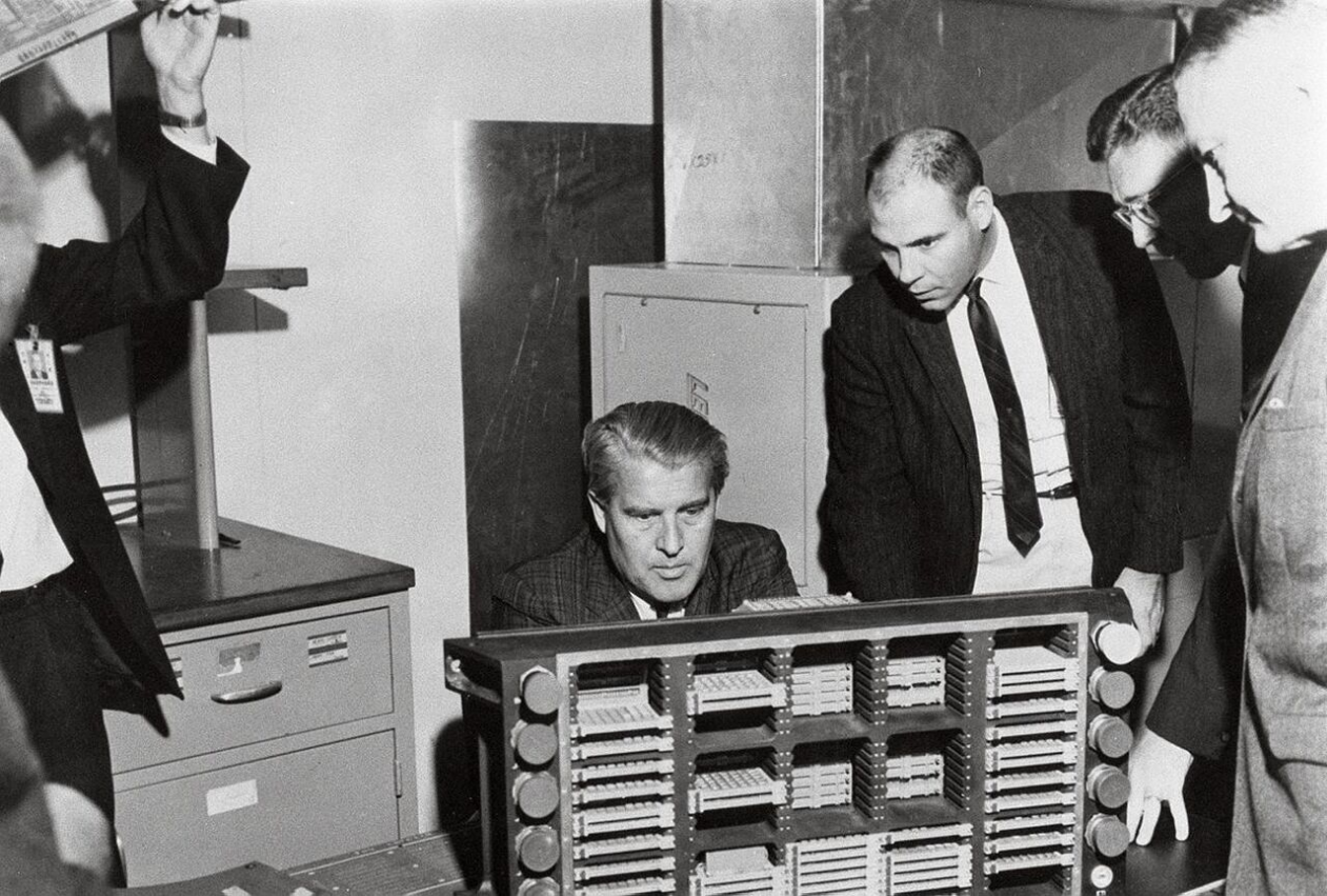
MSFC officials looking at an uncovered LVDC. https://handwiki.org/wiki/index.php?curid=1440178
References
- "Virtual AGC — AGS — LVDC — Gemini: Launch Vehicle Digital Computer (LVDC): Saturn IB and Saturn V Rockets". 2009-08-21. http://apollo.josefsipek.net/LVDC.html.
- Saturn Launch Vehicles TR X-881 https://web.archive.org/web/20050416215829/https://ntrs.nasa.gov/archive/nasa/casi.ntrs.nasa.gov/19710065502_1971065502.pdf
- Haeussermann 1970, pp. 30-31.
- Apollo Study Report, Volume 2, pages 3-36 to 3-37. The log book for the LVDC at National Air and Space Museum says the dimensions were 31x13.1x13 inches and the weight was 90 pounds.
- M.M. Dickinson, J.B. Jackson, G.C. Randa. IBM Space Guidance Center, Owego, NY. "Saturn V Launch Vehicle Digital Computer and Data Adapter." Proceedings of the Fall Joint Computer Conference, 1964
- Apollo Study Report, Volume 2, page 3-4.
- Apollo Study Report, Volume 2, page 2-37
- Haeussermann 1970, pp. 23.
- Pugh, Emerson; Johnson; Palmer, John (1991). IBM's 360 and Early 370 Systems. MIT Press. p. 108. ISBN 978-0262161237. https://archive.org/details/ibms360early370s0000pugh.


