Your browser does not fully support modern features. Please upgrade for a smoother experience.
Submitted Successfully!
 +1 credit
Thank you for your contribution! You can also upload a video entry or images related to this topic.
For video creation, please contact our Academic Video Service.
| Version | Summary | Created by | Modification | Content Size | Created at | Operation |
|---|---|---|---|---|---|---|
| 1 | Bisweswar Ghosh | -- | 5849 | 2022-10-20 10:46:22 | | | |
| 2 | Rita Xu | Meta information modification | 5849 | 2022-10-20 11:03:51 | | | | |
| 3 | Rita Xu | -9 word(s) | 5840 | 2022-10-20 11:04:47 | | |
Video Upload Options
We provide professional Academic Video Service to translate complex research into visually appealing presentations. Would you like to try it?
Cite
If you have any further questions, please contact Encyclopedia Editorial Office.
Ghosh, B.; Abdelrahim, M.; Belhaj, H. Fracture Conductivity Damage on Post Hydrofrac Well Productivity. Encyclopedia. Available online: https://encyclopedia.pub/entry/30453 (accessed on 18 July 2026).
Ghosh B, Abdelrahim M, Belhaj H. Fracture Conductivity Damage on Post Hydrofrac Well Productivity. Encyclopedia. Available at: https://encyclopedia.pub/entry/30453. Accessed July 18, 2026.
Ghosh, Bisweswar, Mumin Abdelrahim, Hadi Belhaj. "Fracture Conductivity Damage on Post Hydrofrac Well Productivity" Encyclopedia, https://encyclopedia.pub/entry/30453 (accessed July 18, 2026).
Ghosh, B., Abdelrahim, M., & Belhaj, H. (2022, October 20). Fracture Conductivity Damage on Post Hydrofrac Well Productivity. In Encyclopedia. https://encyclopedia.pub/entry/30453
Ghosh, Bisweswar, et al. "Fracture Conductivity Damage on Post Hydrofrac Well Productivity." Encyclopedia. Web. 20 October, 2022.
Copy Citation
Hydraulic fracturing or hydro-frac fluids can impede well production due to the damage caused to the reservoir formation and fracture face, generated from adverse interactions with reservoir rock. Understanding the mechanisms of hydraulic fracturing, optimum treatment designs, and pumping/pressure profiles is critical for hydro-frac success.
hydraulic fracturing
fracturing damage
fracture conductivity
guar breaker
1. Background
Tight hydrocarbon reservoirs are oil or gas reservoirs with a matrix permeability of less than 0.1 × 10⁻³ μm [1]. Fluid flow through tight and unconventional reservoirs encounters restrictions governed by a number of mechanisms, such as viscosity, convection, absorption and adsorption, and capillary and inertial forces [2]. These trapping forces restrict fluid flow in micro- and nano-pores, although most hydrocarbons may remain in these pore domains. The macro-pores are considered to be the main contributor to the flow, which may naturally exist or is induced through fracturing [3]. Hydraulic fracturing is one of the fracturing methods in which reservoir rocks are fractured, which extends from the borehole into the formations and is informally called “fracking” or “hydro-frac” [4].
Thus, the primary goal of a frac job is to create contact with high conductivity fracture networks with tight reservoir rock matrices to the maximum possible extent. Hydrofrac is also vital for improving water injection rates in sandstone and carbonate reservoirs [5][6]. Thus, hydrofrac treatments are typically designed to achieve appropriate fracture length, width, and permeability, in commensurate with the formation properties [7]. In general, long and narrow fractures are desired, particularly for tight gas reservoirs [8]. To perform a fracturing job appropriately, the frac fluid must be sufficiently viscous to exert sufficient hydraulic pressure to overcome the rock’s tensile strength and effectively disseminate the fracture through a certain formation length. The fracturing fluids must also be capable of transporting the proppants further into the fracture to ensure that the fracture remains propped even after releasing the injection pressure. A single fracture with the ability to pump large volumes of fluids creates penetration potential for the fracture to a widespread formation. This is the most widely used method within the coalbed methane industry. The second type is explosive fracturing, which involves rapid pressurization of the target formation, thus, resulting in a highly fractured zone of 10–15 ft around the wellbore. This method avoids using liquids for fracturing and propping; thus, sensitive formations can be saved from damage [9]. In this design, a radial fracture pattern is formed because the peak pressures exceed the minimum and maximum horizontal in situ stresses; thus, a favorable fracture geometry with near-wellbore stimulation is achieved. The last method of hydrofrac is pulse fracturing, defined by situ stresses exceeding maximum and minimum stresses and creating a radial fracture pattern. Multiple vertical fractures are formed when this method is applied due to radial extension from the wellbore exhibiting penetration in the order of 10–20 ft [9].
In proppant-packed hydrofrac jobs, the outcome or well productivity would be less than expected unless several possible reservoir- and propped-frac damage mechanisms are understood. Firstly, the effective fracture volume could be reduced by up to 30% due to fracture closure and reservoir pressure drop during the early stage of flowback [10], resulting in the crushing and embedment of the proppants in the fracture surface [11]. The frac-fluid itself is the second most crucial concern for damage as the volume of flowback fluid could be as low as 10–50% of the total injected fluids [12], which means that a large volume of fracturing fluid remains in the reservoir, causing water-phase trapping damages [13] and carbonate and sulfate scale deposition, resulting in pore blockage [14] and, most notably, the loss of permeabilities due to residual polymers and other grouped solids [15]. Thus, to maximize the fracture conductivity and to realize the effectiveness of the fractures within the network, various post-fracturing damage mechanisms must be understood based on the fluid and formation properties for the economic development of tight and unconventional reservoirs [16][17].
1.1. Fracture Orientation, Propagation, and Conductivity
Production optimization through the fracturing process aims to maximize the contact area between the matrix reservoir and the fracture system within the technical and economic limits (see Figure 1 for schematic of fluid flow through a fracture). Creating hydraulic fractures in situ causes stress conditions to the formation and the real-time change along the near-wellbore-controlled fracture propagation [18]. The real-time near-wellbore stress controls not only cause the fracture initiation process but also the fracture propagation and fracture orientation, which is governed by a combination of formation stress properties and the stress provided by the fracturing fluids [19]. However, in the case of a naturally fractured reservoir, the orientation and length of an induced fracture could be severely affected by the existing natural fracture. From a finite-element-based numerical model, it is established that if the angle of approach is sufficiently high, an induced fracture may cross a natural fracture. At a low angle of intersection, it would dilate the natural fracture and break out from one of the tips of the natural fracture [20]. Fracture conductivity is the ability of the fractures to allow fluid flow from the reservoir to the wellbore. As the fracture closing pressure increases, the conductivity decreases. The conductivity of the fractures is among the most critical aspects of hydrofrac success and is therefore included in fracture modeling as one of the primary design parameters. In general, conductivity is the product of propped fracture width (fw in ft) and fracture permeability (k in mD) adjusted under in situ stress and understood as the flowback potential and is measured in mD-ft [21]. Dimensionless fracture conductivity (Fcd) is a more appropriate design parameter, defined as fracture conductivity, Kfw (mD-ft), divided by reservoir permeability (k) multiplied by the fracture half-length, Xf (ft), considered for differentiating finite and infinite conductive fracture. Factors influencing the width/diameter of the fracture include propping density, proppant filling ratio, residual gel filter cake, and embedding tendency. Factors influencing the permeability of the proppant are usually proppant size, sphericity, strength, fines content, and damage due to the residual gel [22].
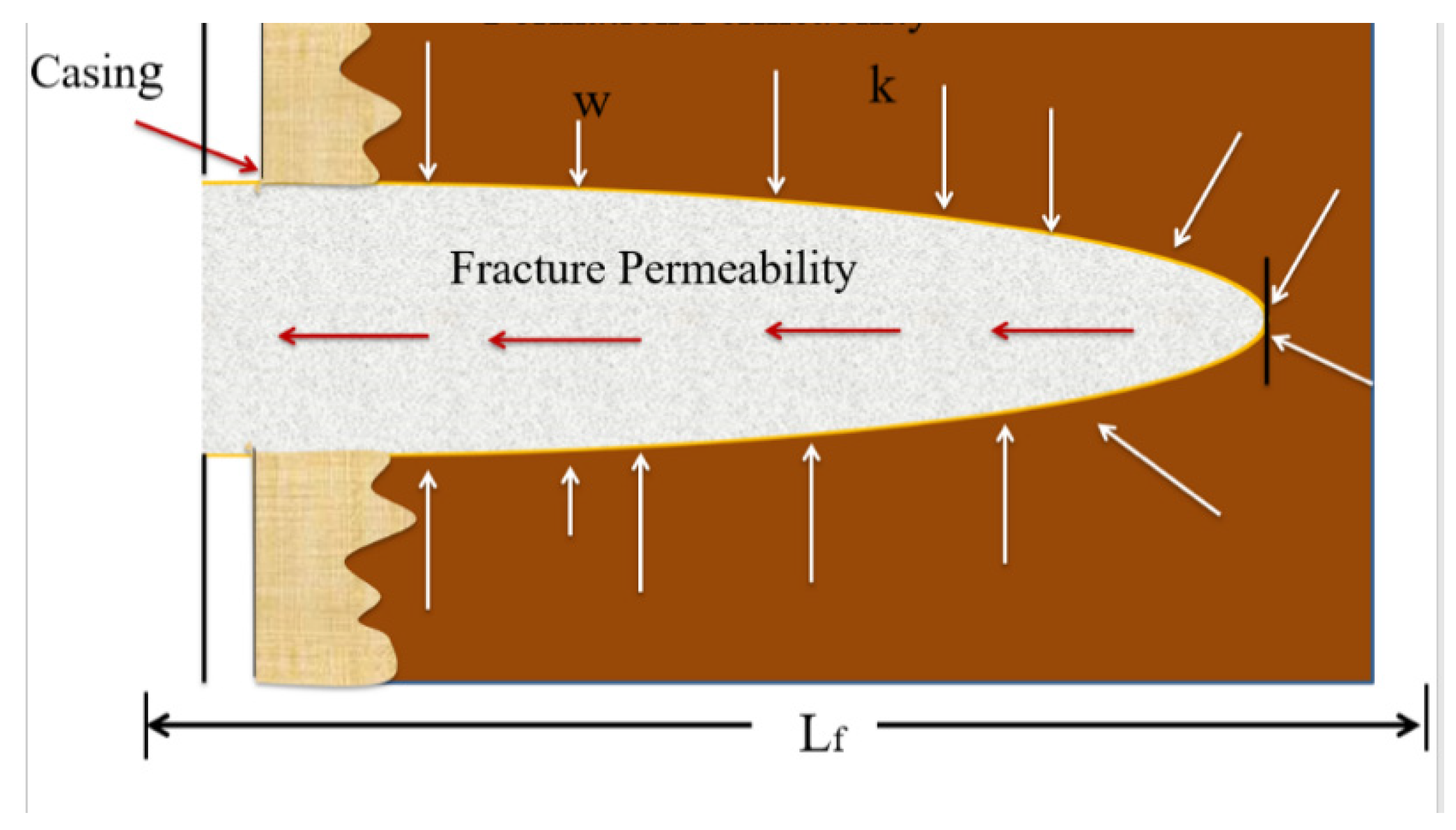
Figure 1. Schematic of fluid flow through a fracture.
1.2. Frac Fluids and Their Properties
The effective suspension and transportation of the proppant into the fracture is achieved when the fracturing fluid rheology is adequately balanced with appropriate viscosifying agents. The success depends on an intricate job design, which includes fracturing fluid design, proppant selection, optimizing injection rate, injection volume, proppant loading schedule, and post-treatment flowback efficiency. Most fracturing fluids use an optimum dose of guar-based polymers (guar and its derivatives). The guar derivatives most commonly used in fracturing fluids include carboxymethyl guar (CMG), hydroxypropyl guar (HPG), and carboxy Methyl hydroxypropyl guar (CMHPG), with each having unique properties [23]. It is of paramount interest to select the correct type of guar at an optimized concentration when designing fracture treatments to deal with the rheology and temperature constraints. A strong comprehension of the polymer consequence towards fracture conductivity and behavioral cleanup is paramount when considering the correct long-term production and cleanup process in a tight gas reservoir. High viscosity, enormous material source, low friction, easy penetration, low filtrate volume, cost-effective utilization, and minimum formation damage characterize an ideal optimal fracturing fluid.
Nowadays, many specialty chemicals are applied in fracturing fluids for special applications. Table 1 provides a brief list of their categories and functions.
Table 1. Ingredients of hydrofrac fluids.
| Component/Category | Function/Remark |
|---|---|
| Water-based polymers | Thickener, transport proppant, reduces leak off information |
| Friction reducers | Limits drag in the tubing |
| Fluid loss additives | Filter cake formation, reduce leak off |
| Breakers | Disable cross-linkers |
| Cross-linkers | Improves the viscosity of the thickener |
| Gel stabilizers | Keep gels active longer |
| Defoamers | Breakdown foam |
| Crosslinked gel systems | Increase viscosity |
| Oil-based systems | Applied in water-sensitive formations |
The fracturing fluids are water- or oil-based [24] and are further subdivided, as below.
1.2.1. Slick-Water-Frac or Water-Frac
Slick-water-frac is a fracture treatment that utilizes a large volume of water to create adequate fracture geometry and conductivity. It is often a combination of water and friction-reducing chemicals. The reasons that slick-water-frac technology is given serious consideration include (1) its cost-cutting in fracturing lower permeability reservoirs, (2) overcoming the challenge of the effective “cleanup” of residual gel from the fracture, and (3) shorter effective half-lengths that are seen more often than not compared to the predicted design [25]. However, most entities embrace conventional crosslinked gel fluid as some aspects of the traditional frac designs are diametrically opposite and not applicable to slick-water-fracs. A slick-water treatment is also referred to as water-frac. Slickening water with either low concentration (~10 ppg) linear gel or polyacrylamide friction reducer is a common ingredient within the fluid system [26]. Slick water fracturing fluid offers extremely low viscosity as compared to a fully crosslinked gel. Poor proppant transport is exhibited by slick-water-frac due to low viscosity and a narrower pumping width compared to the crosslinked gel fluids. Slick water dilates the micro-natural fractures/fissures in a tight formation, increasing the fracture conductivity. It is paramount to pump slick-water-fracs at higher rates of above 100 BPM to deal with the above-mentioned concerns and offer a solution to stimulating long horizontal sections. The pumping rates are of the order of 50–80 BPM for more conventional tight gas reservoirs.
There are benefits and disadvantages when considering slick-water-frac, as far as any design technique is concerned. The potential reduction of gel damage in the fracture doubles up as the primary technical advantage of slick-water-fracs. Compared to 20–40 pptg of polymer in a typical crosslinked gel in the fluid and a metal cross-linker, a slick-water-frac uses only a linear gel (5–10 pptg) or a friction reducer. However, slick-water treatments use substantially higher volumes of fluid despite reducing the gel loading and friction reducer, thus, risking depositing a significant volume of polymer into the fracture. This creates additional difficulties for the industry to break a polyacrylamide friction reducer with effective temperature, time, and suggested breakers as the only way the concern can be solved [27].
Additionally, there is a degree of distributed gel damage and filter-cake formation from the commercial guar derivatives. If the use of light gel continues, then the flow capacity of the fracture is compromised. The potential cost savings are another reason for a move toward slick-water-fracs. A much-reduced chemical package is required during slick-water treatments for easy fluid recycling. The costs for the total treatments are often lower with slick-water treatments when there is a plentiful water supply. However, there is a cost-prohibitive nature when using slick-water treatments in remote locations or areas with a limited water supply, offsetting the benefits of larger required fluid volumes. The cost advantage may not be as great as initially anticipated, given that more horsepower (resulting from the higher injection rates) is required since slick-water jobs are typically much longer. Thus, the structure of the pumping contractors’ bid package and water availability are the predetermining factors in establishing cost savings [28][29].
Slick-water-fracs provide more complex fracture geometry than conventional crosslinked gel-fracs, given that the exercise is affected by higher injection rates and lower viscosity. It has been demonstrated in some shale plays that higher production results from the stimulation of larger areas, thus making the slick-water-frac the preferred design. Better fracture containment (reduced height growth with lower-viscosity fluid) is another potential and proven advantage for a slick-water-frac, which is realized when trying to stay out of underlying water. This is evident in the case of the Ellenberger in some Barnett Shale completions [30]. Finally, there is a possibility of reusing load water flowing back from the existing wells to make up frac fluids on subsequent wells, given that a slick-water-frac typically has a simpler fluid system. Reusing load water is also helpful in areas with expensive or difficult water disposal methods.
Proppant placement/transport is one of the biggest concerns with slick-water-fracs. There is little chance to suspend and transport proppant due to low-viscosity fluids in slick-water fracturing. Additionally, failure to suspend and transport the proppant leads to vertical coverage across the pay zone(s) and lateral placement in the fracture. Later, lateral coverage will be discussed in the proppant transport section. The vertical coverage concern is generated from the fact that, in stimulating the thick intervals, there are possibilities of settling a bank of proppant that fails to cover the entire height of the pay zone. However, vertical coverage can be addressed through an increased number of stages with a limited vertical interval target for each pay zone. The amount of required water for a frac is another concern regarding slick-water treatments since slick-water-frac must be designed for tremendous volumes of water that exceed millions of gallons to place large masses of proppant at low pumping concentrations. However, such an exercise may lead to two potential problems. First, the slick-water-frac will allow greater leak-off and induce more significant formation damages, particularly to water-sensitive formations, due to minimal wall building capacity and massive injection volumes and rates, offsetting the material cost advantages [31]. Second, there could be friction between stakeholders (land owners, environmental groups, farmers, regulators, etc.) and operators due to the limited freshwater availability for oilfield use, adding a high cost to the operation [32].
Finally, there is a narrower pumping width for slick-water-fracs as compared to their crosslinked counterparts due to a direct relationship between fluid viscosity and fracture geometry. It is difficult to place larger diameter proppants and higher pumping proppant concentrations, despite the availability of higher pump rates and pressure, which is one of the major concerns. Thus, many operators have chosen to utilize smaller-sized proppants, including 30/50, 40/70, and in some cases, 100 mesh, and pumped highly diffused concentrations of about <<2 PPA for the bulk of their treatment [33].
1.2.2. Water-Based Gelled Fluids
Guar gum and its derivatives are the most common polymers used in water-based fracturing fluids, accounting for nearly 90% of all gelled fracturing fluids. Natural guar is chemically modified through etherification, esterification, and crosslinking reactions to achieve enhanced properties [34][35]. These modified guar derivatives gained popularity because of their unique properties, such as high molecular weight (ranging from 1 to 2 MD), helping to generate high viscosity at low concentration, quick hydration, stability at a higher temperature, and a greater pH range (pH 4.5–10). They also crosslink with metals, biocompatible, biodegradable, and non-toxic nature [23].
Natural Guar Gum
Natural guar gum is an extract from guar (Cyamopsis tetragonolobus) seeds. It is a natural polysaccharide with a β-D mannopyranosyl (mannose) backbone linked with D-galactopyranosyl (galactose) units as side branches (Figure 2) and bonded by α-1,6 linkages [36]. The mannose to galactose ratio is usually between 1.8:1 and 2:1 [37], which governs its rheological properties [38]. Guar-based hydrofrac fluids are known as standard fracturing fluids within the oil industry. Natural guar has impurities to different degrees, which provides increased fluid loss control through the creation of filter cakes at the interface. It is observed that guar easily hydrates at a wide range of pH, given that the optimal pH for guar hydration ranges between 6.5 and 7.5 [39]. The guar is stable at a high pH and unstable at a low pH when hydrated, and thus, as a linear guar gel, is stable up to 80 °C. However, its thermal stability may go up to 150 °C for short periods, provided the gel is crosslinked with a metal ion [40].
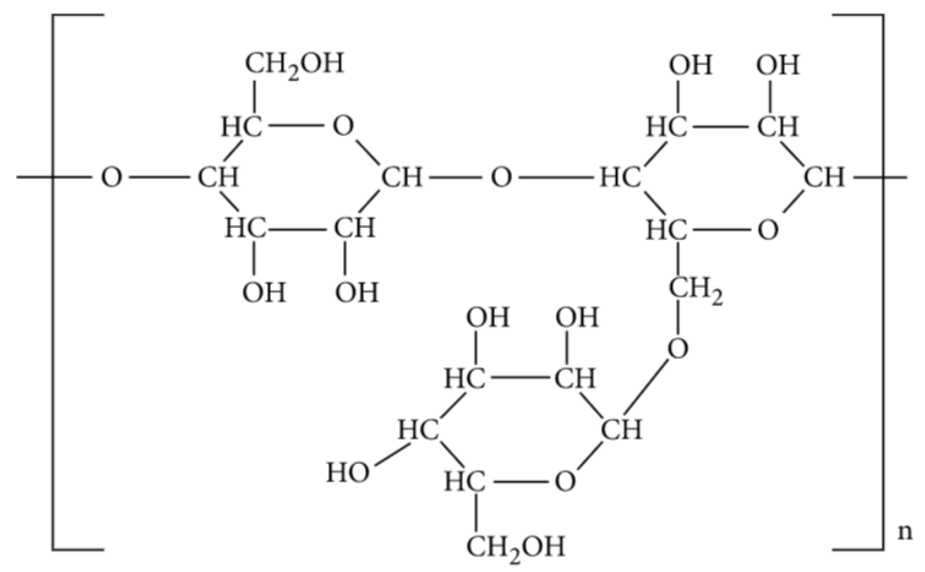
Figure 2. Molecular Structure of guar gum [41].
Hydroxypropyl Guar (HPG)
A reaction between propylene oxide and a highly purified guar stock is used to manufacture HPG. The guar endosperm splits are exposed to a series of water and acid soaks to remove the embryo as well as the majority of the hull before grinding to achieve a highly purified guar. The impurities of the guar are further reduced by approximately 2% of insoluble material through the purification process. HPG is a versatile viscosifier compared to guar since its resulting molecule is nonionic and, therefore, is associated with many advantages [42]. The hydration process for HPG is faster than it is for guar, and it is characterized by higher viscosity at similar concentrations to the guar. The addition of the propylene oxide group to HPG helps it gain better temperature stability due to stabilized polymer that withstands thermal degradation. Filter-cake buildup fails to regenerate on the fracture face due to the reduction of residue and is thus a challenge exhibited during a high-permeability zone fracturing. Therefore, despite having a higher fluid loss, HPG is compatible with methanol, exhibits higher temperature stability, and is less damaging [43]. Figure 3 shows the molecular structure of HPG.
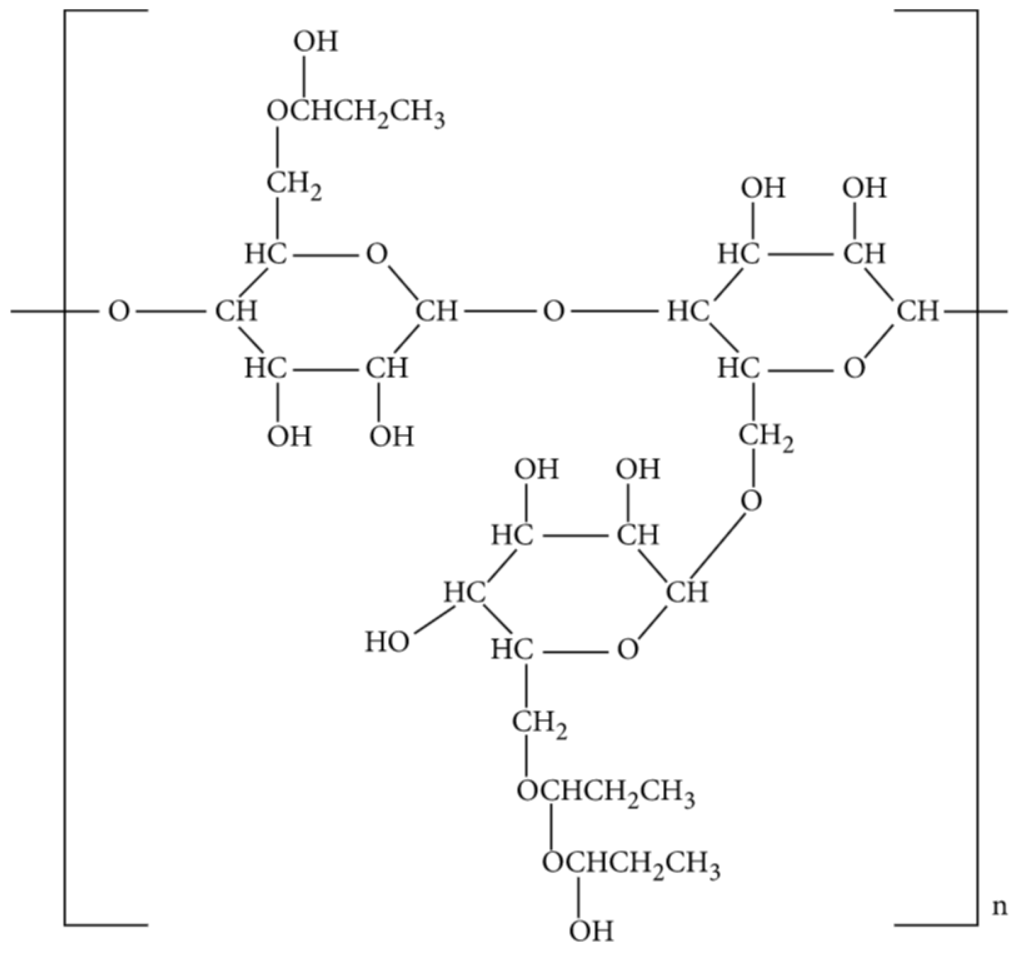
Figure 3. Molecular structure of HPG [41].
Carboxymethyl Hydroxypropyl Guar (CMHPG)
Compared to HPG, CMHPG has lower residue with only 1 to 2% impurities. Moreover, the temperature stability of CMHPG and the rate of hydration are way better and faster than that of guar and HPG. From another perspective, CMHPG provides a super “clean” gel system due to its high tolerance for methanol, which is one of the best water-miscible solvents. CMHPG is characterized by extra potential energy to assist in the load fluid cleanup and recovery since it is compatible with carbon dioxide (CO2). Another associated advantage of CMHPG is that it allows crosslinking both at a high and low pH. However, there exists a common disadvantage of CMHPG and HPG as both exhibit reduction during fluid-loss control, thus, increasing the cost of CMHPG over guar and HPG [44]. Figure 4 displays the molecular structure of HPG.
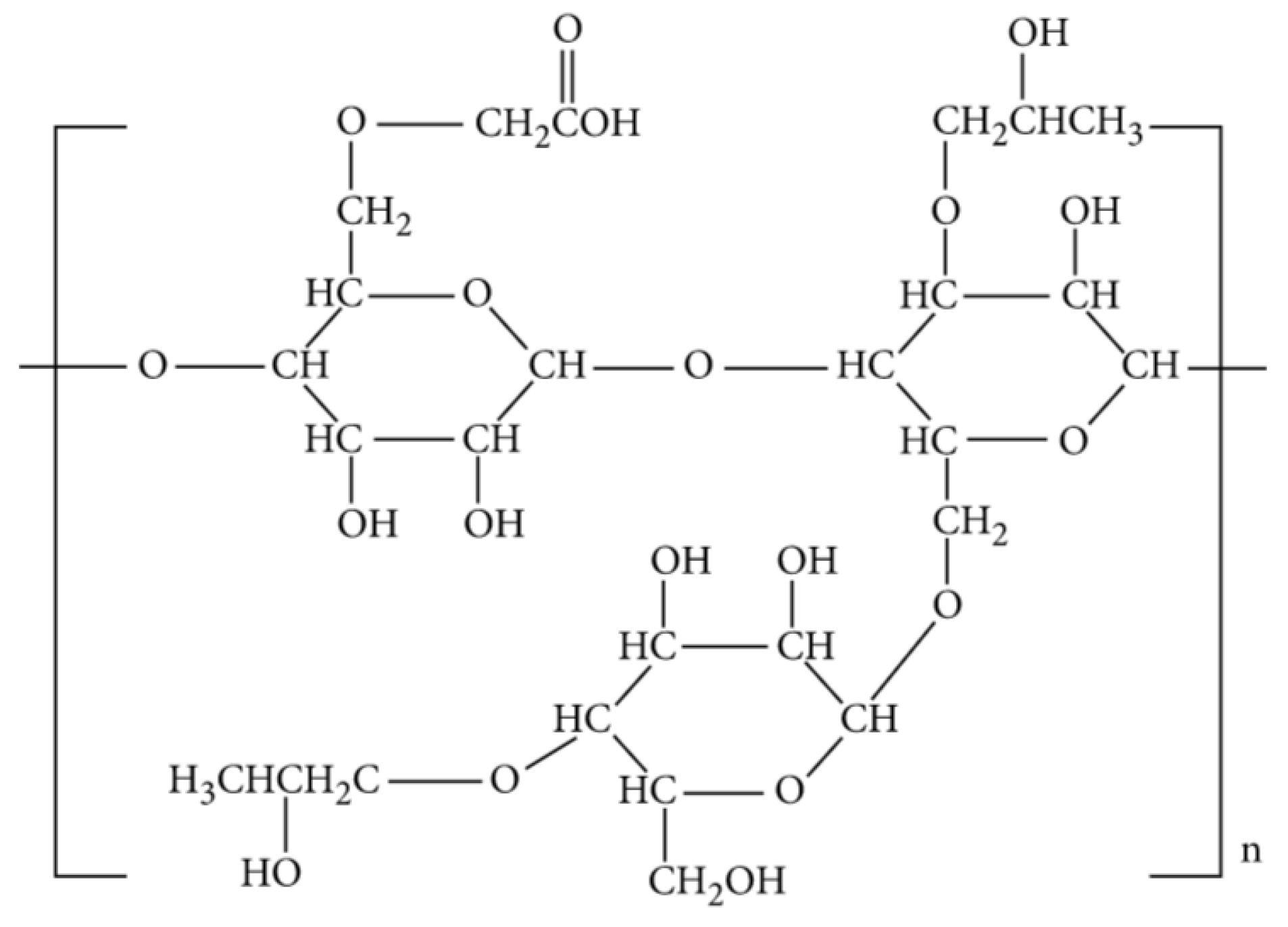
Figure 4. Molecular structure of CMHPG [41].
Foam-Based Fracturing Fluids
Due to the limitations of traditional fluids and the advantages of foam as a fracturing fluid, foam stability and rheological qualities have been extensively studied for fracturing applications [45]. Foam-based fracturing fluids carry proppants through impermeable hydrocarbon reservoirs. Carbon dioxide and nitrogen are the gases required for the formation of foam-based fracturing fluids. The foam’s gas components are capable of providing the additional drive necessary to remove water from the fracturing zone. The purpose of polymer-free foams is to mitigate the clogging of pore throats and the formation damage caused by clay swelling. Nonetheless, the primary concern with foam fracturing fluid applications is the foam’s stability and propagation in micro- and nano-fissures that occur randomly in natural fractures under reservoir conditions associated with high-temperature and high-pressure reservoirs [46]. The durability of foam is a major concern, which can be improved by adding polymer to bentonite clay via adsorption at the foam’s air–water interface [47].
Viscoelastic Surfactant (VES) Fluids
VES was developed to come up with a fluid that had the potential to eliminate the shortcomings of water-based gelled fluids. VES is viscous under extreme shear conditions and produces no residue as opposed to polymeric hydrofrac fluids. VES has been applied to gas wells and, in some cases, in coal seams. VES systems may possess worm-like micelle structures, vesicles, or lamellar structures [48]. VES also acts as a thickener, making it very significant to the performance of the fracturing fluid. The most commonly used VES are anionic, cationic, zwitterionic, single-chain, and Gemini surfactants. VES prepared by Gemini surfactants is superior to conventional surfactants because they are composed of two identical or different amphiphilic moieties [49][50]. Because of the presence of two hydrophobic groups in the structure, Gemini surfactants have higher water-solubility and hard-water tolerance and can also self-associate into micelles quicker [51]. VES is often preferred as a hydrofrac fluid instead of polymer-based fracturing fluids due to its gel-breaking mechanism. The gel breaks into a water-thin solution when the residual VES comes into contact with hydrocarbon fluids. VES fluids can be used to treat virtually all gas and oil wells below 240 °F [52].
The ability of VES to reduce the fracturing fluid’s surface tension facilitates water flow in the pores within the rock [31]. It is important to note that VES is not recommended for high permeability reservoirs above 200 mD as it would increase leak-off rates and, thus, cannot reduce their surface tension [53]. Sullivan et al. [54] optimized VES for high-permeability sandstone formation and advised that VES should only be used in reservoirs under 100 mD. It is also important to note that the thermal stability of VES can be unreliable in temperatures exceeding 135 °C unless a concentration above 60 pptg is used [55].
The surfactant in VES has a low molecular mass, a long hydrophobic tail, and a hydrophilic head. This provides it with complex micellar structures when exposed to salts such as ammonium chloride, ammonium nitrate, and potassium chlorides. Because of their ability to build complex structures, they can quickly form high-viscosity mass. Some of the historical events that utilized VES in similar processes include the south Texas wells, which had an 82 °C bottom-hole temperature with a 0.1 mD reservoir permeability. The well produced ten times the amount of gas, which indicates a high level of success [56].
The main concern for VES is its leak-off rates, especially in >100 mD permeability reservoirs. The reason behind the high leak-off rate is the lack of polymer. The polymer gels are three-dimensional, thus, reducing leak-off rates as they form filter cakes. According to Huang et al. [53], zinc oxide can reduce leak-offs in VES by creating crosslink formations that can help create filter cakes. The zinc particles used in this case measure 100 nm in size, with a diameter of 35 nm. A combination of zinc particles and VES results in the creation of electrostatic and van der-Waals forces, which hold the particles together, thus, enhancing their structure. In another study, a ten ppg concentration of amidoamine oxide was added, resulting in a viscosity enhancement from just 15 poise to an average of 1100 poise. The settling time also increased to 90 min from 15 min after the formulation of the nano-VES system. To confirm the effectiveness of the solution, the researchers pushed the fluid through a 400 mD and 0.25-inch thick ceramic disk under a less than 300 psi pressure drop. The results indicated that the leak-off rate was 80 mL per 70 min compared to 425 mL in 5 min. However, when the authors increased the concentration to 30 pptg, the leak-off rate increased [57][58]. Though the studies conducted in a laboratory environment were promising, the field results were not so. According to the studies conducted in the 1990s, where VES was applied in a relatively large number of wells, there was a need for reviving fractured wells by adopting remedial actions. In this aspect, Mahdaviara et al. [59] noted that hydrocarbons could break VES fluids more efficiently when specific amounts of salts are removed from the brine. The authors concluded that it is not possible to achieve these two conditions in most cases as the wells might fail to produce sufficient hydrocarbons to break the VES solutions. In this case, the authors advised adopting breakers such as iron, ascorbic acid, and sodium citrate, among other chelating agents. When metallic ions are used, they break the gel by attacking the micellar structures. However, sodium citrate and other chelating agents are only used in fine-tuning the breaking process and reducing the number of metals used in the breaking process.
Crosslinking of Guar and Guar Derivatives
The crosslinking of polymer chains with multivalent ions creates a 3D superstructure, resulting in enhanced gel viscosity and improved thermal stability with a lesser polymer load. This process enhances the proppant suspension and transport capacity by many times more than that of uncrosslinked polymer (linear) fluids. The proven crosslinking agents for guar-based polymers are borate and metal compounds of zirconium (Zr) and titanium (Ti).
Borate-Cross-Linked Guar Gel
Highly viscous frac gel can be prepared by crosslinking guar gum with borax (di-sodium tetraborate and heptahydrate) in a single step and at room temperature (Figure 5).
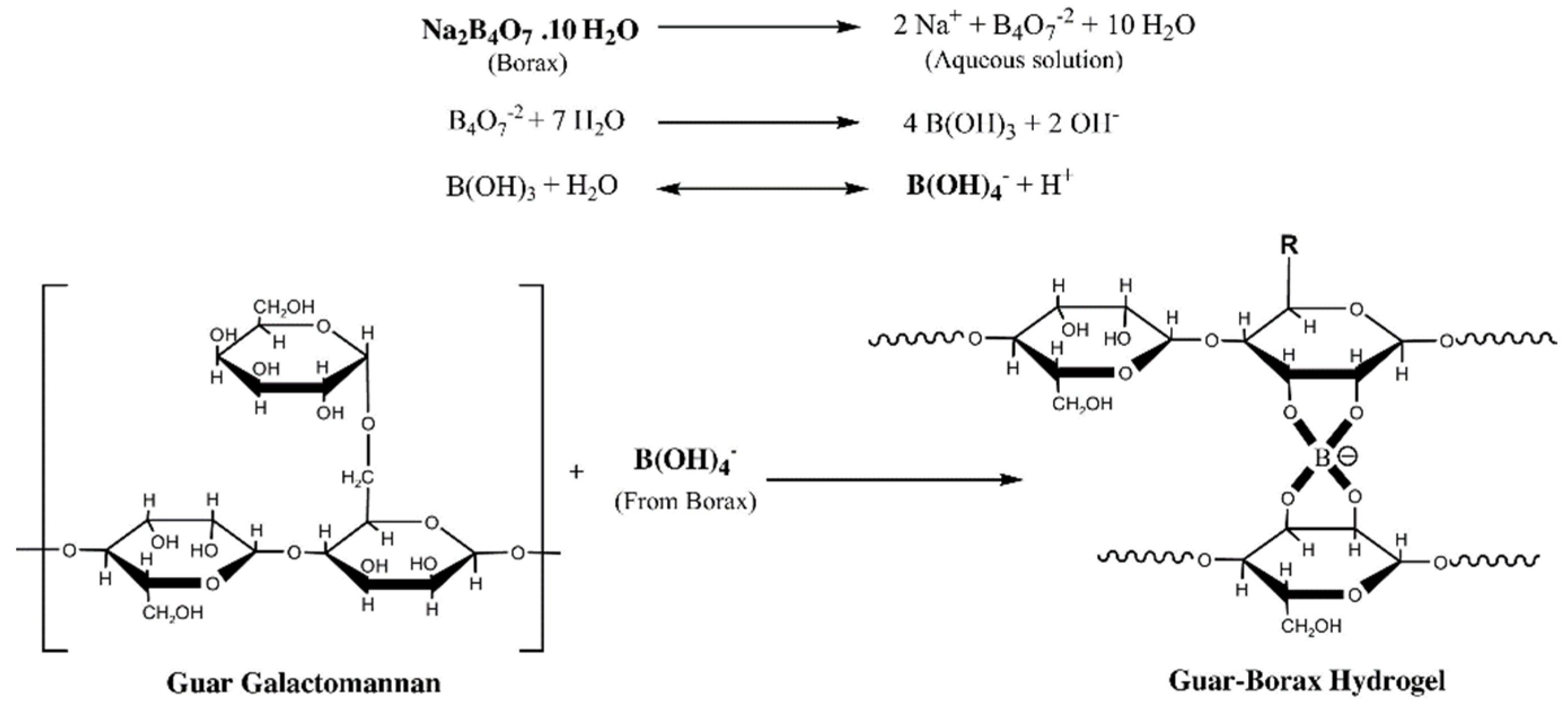
Figure 5. Borax crosslinked guar gum hydrogels [60].
In field applications, a higher fluid pH is required when borate crosslinked guar fluids are subjected to bottom-hole temperatures of above ~200 °F. Using bicarbonates, amines, hydroxides, and/or carbonates as buffers helps to achieve and maintain a high fluid pH. This sometimes allows the use of produced water in preparing borate crosslinked frac fluid [61]. However, when produced water contains high concentrations of calcium and magnesium, these precipitate out at a high fluid pH, consuming the buffering materials and reducing the fluid’s stability at high temperatures. Additives such as scale inhibitors can help to arrest the precipitation and stabilize the borate-crosslinked fluids when produced water is used. Otherwise, it is limited to the use of freshwater on high-temperature wells above about 200 °F [62]. More than 200 fracturing stages were successfully pumped in the Delaware basin, West Texas, through the implementation of scale inhibitors [63].
Li et al. [64] reported the possibility of bacterial degradation while formulating borate-crosslinked guar fluids with produced water. Bacterial enzymes quickly break the polymer chain when exposed to polymers like guar. There are several mitigation methods available, and one such method is the introduction of zirconium compounds in the frac fluid [65].
Offshore operations such as frac-and-pack and hydrofrac jobs use borate-crosslinked guar fluids formulated with seawater. Maintaining the stability of the crosslinked structures requires borate-crosslinked guar gels to have a pH of about 9 or higher. The fluid pH usually drops when the calcium or magnesium ions present in seawater precipitate out with the hydroxide anions and, in the process, destabilize the borate-crosslinked fluids. However, borate-crosslinked guar fluid prepared using typical seawater (close to the fluid pH of 9.2–9.3) does not precipitate magnesium hydroxide or calcium hydroxide. Thus, the borate-crosslinked guar fluids with a fluid pH should be slightly above 9 for offshore fracture jobs [63].
Metal-Crosslinked Guar Fluids
Guar polymers can also be crosslinked with metal cross-linkers such as zirconium and titanium compounds [66]. The advantage of metal crosslinking over borate is their enhanced thermal stability and the stability of the gel below pH 7. Thus, metal cross-linkers are preferred in cases of foamed fluid with CO2 (which lower the fluid pH). The low fluid pH also prevents scaling when produced water is used with high concentrations of divalent cations such as calcium, strontium, and barium ions [67]. Zr- and Ti-crosslinked guar fluids provide better thermal stability than borate crosslinked gels when produced water is the only source of water. Leiming et al. [68] reported the successful application of metal crosslinked gels in wells at bottom hole temperatures up to ~250 °F, with the produced water sources having TDS up to ~300,000 mg/L, and a hardness of up to ~44,000 mg/L.
2. Fracture Conductivity Damage
A fracturing fluid inevitably causes reservoir damage, categorized by two types: external damage and internal damage. The crushing of the embedded proppants mainly causes external damage in the form of the fracture plugging. Residual polymers and chemicals, after the flowback, cause fracture face damage, which is also a type of external damage [69]. On the other hand, internal damages are caused by high fluid leak-offs, relative permeability hysteresis, capillary effects, and clay swelling. Residual gel fracturing fluid, proppant crushing, embedment, and particle migration are the main causes of fracture conductivity damage [70]. Ref. [71] reported that FC was reduced by over 90% in fracture conductivity because of the abovementioned factors.
The extent of internal damage depends on the water sensitivity of the rock, the extent of water or gas lock, and the quantity of macromolecule adsorption, in addition to pore blockage due to fines migration. Ultimately, several factors will impact the cleanup process, including fracture geometry, conductivity, non-Darcy flow effects, heterogeneity fluid viscosity, formation temperature, breaker, gel residue, operational procedures, and, most importantly, pressure drawdown [72]. The main drawbacks of hydrofrac are clay swelling, fluid leak-off, precipitation of fines migration, and fracturing fluid residues. According to some studies, gel fracture treatments show excessive residual damage compared to slick-water fracture [73]. However, contradictory results reported by [74] say that damage by slick-water could be more severe than HPG fracturing fluid due to higher water sensitivity and higher macromolecule adsorption.
The studies also indicate that the rate of flowback of residual polymer from reservoirs below 250 °F is less than 40%. This results in the failure of an adequate polymer cleanup process. Research conducted by [75] to assess the main hindrances to water and gas flow in wells suggested that relative permeability and capillary pressure should be considered when conducting the cleanup process as they affect the results of the entire process. There is also a possibility of a substantial pressure drop in cases where fluid invasion damages the reservoir rock permeability or when a gas blockage is likely to occur. In scenarios where the permeability of the reservoir is undamaged, there will not be any water or gas blockage if the capillary pressure is lower than the pressure drawdowns. According to [76], however, when the relative formation permeability is lower than the fracture conductivity, there will not be much damage, and the cleanup process would go on smoothly since the fracture fluid would easily break, providing lower viscosity after treatment. There would also be a possibility of recovering up to one-half of the injected fracturing fluid in 2–6 days, as long as there is gel degradation and adequate fracture conductivity [76]. The author also stated that, in situations where the fracture conductivity is low, the gas is sure to enter into the wellbore fracture. This can also be enhanced by ensuring adequate fracture length and well productivity time. The main disadvantage of Tannich’s model is that it did not allow for the capillary forces, the damage in the fractures, and the closure stress effects surrounding the fracture.
In a study by Gdanski et al. [77], a large reduction in gas production and increment water production was experienced when a 90% fracture face permeability damage occurred. This was calculated based on the measures established by [78], who aimed to determine the relationship between well productivity and fracture face damages. Another study that examined the impacts of fracture conductivity damage was conducted by [79]. They used water-based fracturing fluid and concluded that higher gas production, faster fracture fluid cleanup, and relatively longer fracture lengths could be achieved when water-based fluids were used to increase the conductivity rate. This means that fracture conductivity results in high gas flow rates and faster fracture cleanup processes than formation permeability, water mobility in the reservoirs, and fracture closure effects.
2.1. Guar Polymer Damage
The residue of the guar-based fracturing fluid can lead to gas sorption and diffusion issues because of the guar-coating. The gel remnants cause more permeability damage to the natural fracture in contrast to the induced fracture. Fortunately, in the case of decent gel-breaking conditions, the fracture permeability can regain its normal levels through water flushing in a high-temperature environment [80]. The level of damage by hydroxypropyl guar (HPG) frac fluid was quantified by [74]. Their NMR-based study showed that the HPG fracturing fluid caused 30.43% core permeability damage, of which 23.26% was due to water block, and only 1.11% was due to polymer adsorption. In a study conducted by Ghosh et al. [81], it was established that crosslinked guar gels are less prone to fracture face damage compared to linear gels by a factor of two or more.
2.2. Fracture Face Skin
Fracture face skin (FFS) is described as an impairment of the fluid flow from the matrix into the fractures. However, fracture face skin has little effect on the productivity of multi-fractured horizontal wells. The worst possible scenario of well productivity damage may not exceed the five percent marker, according to [78], who suggested against using low-damaging high-cost fracturing fluids that do not justify the incurred expenses in most hydrofrac operations. However, in many actual field practices, this argument was not valid.
2.3. Damage Due to Frac Fluid Invasion
Swelling and migration constitute the main reasons for formation damage caused by hydrofrac treatments in shale formations. Throughout the process, the water sensitivity of the shale causes a reduction in fracture conductivity due to proppant embedment and pore blocking. Flowback fluid causes significant damage since it produces carbonate and sulfate deposits, allowing more scale creation within the reservoir. Consequentially, remnants of the fracturing fluids after gel breaking and other solid residues clustering and causing some sort of blockage to the fractures, leads to permeability damage. Hydrofrac produces a complex fracture network, yet few are useful for production because the damages prevent their operative growth [82].
The fracturing fluids retrieved during the flowback also lead to several unwarranted conditions. Firstly, the alteration of relative permeability to hydrocarbons in the rock. Additionally, it damages and disturbs the chemical equilibrium of the rock/fluid system, causing a physically- and chemically-altered zone of rock near the fracture face, and ultimately leads to a reduction in rock strength because of the fluid invasion [83]. To attain higher levels of production, it is essential to comprehend how the rate of combined fluid leak-off and imbibition (and the amount of fluid invading the rock matrix) correlate [84]. Slick water fracturing is a poor choice for water-sensitive shale and clay-rich formations. A 39.08% permeability impairment was observed due to the water sensitivity of shale alone, resulting in the hydration, swelling, dispersion, and migration of the clay fines and deposition of the scales [74].
2.4. Polymer Filter Cake Damage
The fracture fluid leaks off into the reservoir formation during fracturing, while most polymers remain within the proppant pack, creating a filter cake [85]. A polymer filter cake is beneficial during fracturing as it helps to reduce the leak-off of the base fluid into the reservoir formation, keeping the hydraulic pressure inside the fracture and increasing the propagation of the fracture. Conversely, the filter cake must be removed after a fracture treatment to attain maximum conductivity and generate a hydrocarbon flow path. The polymer concentration in the gel can increase from 20–40 to 300–1000 lbm/1000 gallons upon closure. Sometimes the polymer concentration becomes so high that it cannot be fully degraded by the breaker additives anymore, as evidenced in low and high permeability formations.
Moreover, the temperature-resistant additives used for high-temperature reservoirs provide long-term resistance to thermal degradation of the cake, are another cause of concern [86]. Therefore, the goal is to eliminate or minimize the filter cake to obtain optimum fracture conductivity. Unfortunately, though the general physical procedures for filter-cake buildup are well understood, the fundamental property and filter cake removal mechanism has not been adequately understood [77].
2.5. Fracture Conductivity Damage Due to Proppant
Significant factors influencing the fluid conductivity of a proppant-packed fracture include proppant size, shape, and size distribution. The selection of proppant type generally relies on the formation temperature and the predicted closure stress. Soft formations facilitate the embedment of the proppant into the formation and cause formation spalling, leading to conductivity damage. This is often alleviated by using a reduced-size proppant [87]. Proppant embedment leads to mechanical damage or pseudo-skin and, as a result, hinders the normal operation of the near-hydrofrac zone. As per [88], productivity and flow assurance significantly deteriorates when near-fracture mechanical damage is exhibited. The proppant embedded layers thicken when the proppant penetrates the matrix of the reservoir formation, causing further mechanical damage as well as fracture conductivity damage.
Closure stress increase is exhibited during production following hydrofrac, but the increase rate depends on the proppant concentration, size distribution, type of reservoir formation, and hydrofrac surface geometry [89][90]. As observed by [91], proppant embedment results in the deformation of the formation grain, near-fracture-face matrix damage, grain crushing and disintegration, and fine particle generation. The stress-induced mechanical interaction between the fracture surface and proppant is responsible for the above. Thus, pore spaces are compacted or plugged, and the region’s permeability is reduced, confining the fine particles internally, which may get released gradually during production. The realization of the fractured skin parameters has been described by [78] as damaged and non-damaged proppant-packed zones, characterized as hydraulically near-fracture or created fracture reservoir formation damage. Proppant crushing due to high closure stress is a great concern that necessitates a judicious selection of proppant based on laboratory experiments. Liang, X. et al. [92] proved that low-strength sand proppants are subjected to higher crushing compared to ceramic proppants, resulting in significantly higher fracture conductivity damage (Figure 6).
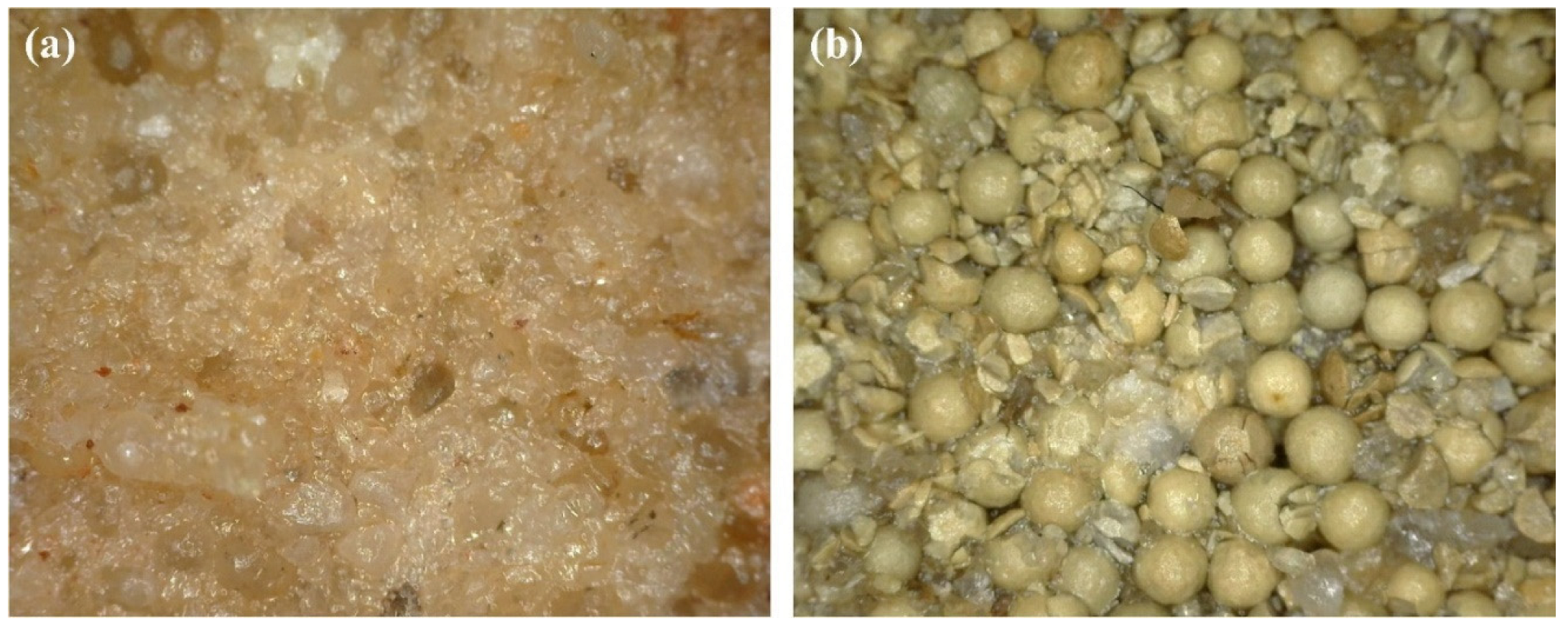
Figure 6. Crushing of proppant after fracture closure ((a): sand proppant, (b): ceramic proppant) [92].
References
- Aldhuhoori, M.; Belhaj, H.; Ghosh, B.; Fernandes, R.; Alkuwaiti, H.; Qaddoura, R. Unique Approach in Modelling Flow in Tight Oil Unconventional Reservoirs with Viscous, Inertial and Diffusion Forces Contributions. In Proceedings of the International Conference on Offshore Mechanics and Arctic Engineering, Cancún, Mexico, 5–6 April 2021.
- Aldhuhoori, M.; Belhaj, H.; Ghosh, B.; Fernandes, R.; Alkuwaiti, H.; Qaddoura, R. A Micro/Nano Scale Fluid Flow Model in Tight Unconventional Reservoirs. In Proceedings of the Abu Dhabi International Petroleum Exhibition & Conference, Abu Dhabi, United Arab Emirates, 9–12 November 2020.
- Belhaj, H.; Qaddoura, R.; Ghosh, B.; Saqer, R. Modeling Fluid Flow in Tight Unconventional Reservoirs: Nano-Scale Mobility/Trapability Mechanistic Approach. In Proceedings of the SPE Gas & Oil Technology Showcase and Conference, Dubai, United Arab Emirates, 21 October 2019.
- Wu, Z.; Cui, C.; Jia, P.; Wang, Z.; Sui, Y. Advances and challenges in hydraulic fracturing of tight reservoirs: A critical review. Energy Geosci. 2022, 3, 427–435.
- Alklih, M.Y.; Ghosh, B.; Al-Shalabi, E.W. Tight Reservoir Stimulation for Improved Water Injection—A Novel Technique. In Proceedings of the International Petroleum Technology Conference, Doha, Qatar, 19–22 January 2014.
- Wang, D.B.; Zhou, F.; Li, Y.; Yu, B.; Martyushev, D.; Liu, X.; Wang, M.; He, C.; Han, D.; Sun, D. Numerical simulation of fracture propagation in Russia carbonate reservoirs during refracturing. Pet. Sci. 2022.
- Al-Attar, H.; Alshadafan, H.; Al Kaabi, M.; Al Hassani, A.; Al Mheiri, S. Integrated optimum design of hydo-frac for tight hydrocarbon-bearing reservoirs. J. Pet. Exp. Prod. Tech. 2020, 10, 3347–3361.
- Economides, M.J.; Hill, D.; Ehlig-Economides, C.; Zhu, D. Petroleum Production Systems; Prentice Hall: Hoboken, NJ, USA, 2013.
- Jennings, A.R., Jr. Fracturing fluids-then and now. J. Pet. Technol. 1996, 48, 604–610.
- Xu, Y.; Dehghanpour, H.; Ezulike, O.; Virues, C. Effectiveness and time variation of induced fracture volume: Lessons from water flowback analysis. Fuel 2017, 210, 844–858.
- Arshadi, M.; Zolfaghari, A.; Piri, M.; Al-Muntasheri, G.A.; Sayed, M. The effect of deformation on two-phase flow through proppant packed fractured shale samples: A micro-scale experimental investigation. Adv. Water Resour. 2017, 105, 108–131.
- Zhou, W.; Dilmore, R.; Kleit, A.; Wang, J.Y. Evaluating fracking fluid flowback in Marcellus using data mining technologies. SPE Prod. Oper. 2016, 31, 133–146.
- You, L.; Xie, B.; Yang, J.; Kang, Y.; Han, H.; Wang, L.; Yang, B. Mechanism of fracture damage induced by fracturing fluid flowback in shale gas reservoirs. Natural Gas Ind. B 2019, 6, 366–373.
- Nicot, J.-P.; Scanlon, B.R.; Reedy, R.C.; Costley, R.A. Source and fate of hydraulic fracturing water in the Barnett shale: A historical perspective. Environ. Sci. Technol. 2014, 48, 2464–2471.
- Guo, J.; He, J. Microscopic mechanism of the damage caused by gelout process of fracking fluids. Acta Pet Sin. 2012, 33, 1018–1022.
- Xu, C.; Kang, Y.; You, Z.; Chen, M. Review on formation damage mechanisms and processes in shale gas reservoir: Known and to be known. J. Nat. Gas. Sci. Eng. 2016, 36, 1208–1219.
- Wu, X.; Pu, H.; Zhu, K.; Lu, S. Formation damage mechanisms and protection technology for Nanpu nearshore tight gas reservoir. J. Pet. Sci. Eng. 2017, 158, 509–515.
- King, G.E. Thirty years of gas shale fracturing: What have we learned? In Proceedings of the SPE Annual Technical Conference and Exhibition, Florence, Italy, 20–22 September 2010.
- Xu, W.; Thiercelin, M.J.; Walton, I.C. Characterization of hydraulically-induced shale fracture network using an analytical/semi-analytical model. In Proceedings of the SPE Annual Technical Conference and Exhibition, New Orleans, LA, USA, 4–7 October 2009.
- Rahman, M.M.; Rahman, S.S. Fully coupled finite-element-based numerical model for investigation of interaction between an induced and a preexisting fracture in naturally fractured poroelastic reservoirs: Fracture diversion, arrest, and breakout. Int. J. Geomech. 2013, 13, 390–401.
- Zhang, J.; Zhu, D.; Hill, A.D. Water-Induced Fracture Conductivity Damage in Shale Formations. In Proceedings of the SPE Hydraulic Fracturing Technology Conference, The Woodlands, TX, USA, 3–5 February 2015.
- Wang, H.Y.; Sharma, M.M. Estimating Unpropped-Fracture Conductivity and Fracture Compliance from Diagnostic Fracture-Injection Tests. SPE J. 2018, 23, 1648–1668.
- Abdelrahim, M.; Ghosh, B.; Belhaj, H.; Ghosh, D. High-Temperature Stable Specific Enzyme for Guar Polymer Based Fracturing Fluid Degradation. In Proceedings of the SPE/IATMI Asia Pacific Oil & Gas Conference and Exhibition, SPE-205569-MS, Virtually, 12–14 October 2021.
- Al-Taq, A.A.; Al-Khaldi, M.H.; Alfakher, B.M.; Mechkak, K. Successful Application of TSE-Based Fracturing Fluids in Proppant Fracturing for Unconventional Carbonate Source Rock. In Proceedings of the SPE International Hydraulic Fracturing Technology Conference and Exhibition, Muscat, Oman, 16–18 October 2018.
- Handren, P.J.; Palisch, T.T. Successful Hybrid Slickwater Fracture Design Evolution--An East Texas Cotton Valley Taylor Case History. SPE Prod. Oper. 2009, 24, 415–424.
- Birdsell, D.; Rajaram, H.; Dempsey, D.; Viswanathan, H.S. Hydraulic fracturing fluid migration in the subsurface: A review and expanded modeling results. Water Resour. Res. 2015, 51, 7159–7188.
- Wang, J.; Zhou, F.; Bai, H.; Li, Y.; Yang, H. A Comprehensive method to evaluate the viscous slickwater as fracturing fluids for hydraulic fracturing applications. J. Pet. Sci. Eng. 2020, 193, 107359.
- Funkhouser, G.P.; Norman, L.R. Synthetic polymer fracturing fluid for high-temperature applications. In Proceedings of the International Symposium on Oilfield Chemistry, Houston, TX, USA, 5–8 February 2003.
- Palisch, T.T.; Vincent, M.C.; Handren, P.J. Slickwater fracturing: Food for thought. SPE Prod. Oper. 2010, 25, 327–344.
- Kakadjian, S.; Thompson, J.; Torres, R.; Trabelsi, S.; Zamora, F. Stable fracturing fluids from waste water. In Proceedings of the SPE Unconventional Resources Conference Canada, Calgary, AB, Canada, 5–7 November 2013.
- Al-Muntasheri, G.A.; Nasr-El-Din, H.A.; Hussein, I.A. A rheological investigation of a high temperature organic gel used for water shut-off treatments. J. Pet. Sci. Eng. 2007, 59, 73–83.
- Liang, F.; Sayed, M.; Al-Muntasheri, G.A.; Chang, F.F.; Li, L. A comprehensive review on proppant technologies. Petroleum 2016, 2, 26–39.
- Reinicke, A.; Rybacki, E.; Stanchits, S.; Huenges, E.; Dresen, G. Hydraulic fracturing stimulation techniques and formation damage mechanisms—Implications from laboratory testing of tight sandstone–proppant systems. Geochemistry 2010, 70, 107–117.
- Lam, K.S. New aspects of natural products in drug discovery. Trends Microbiol. 2007, 15, 279–289.
- Blamble, E.A.; Pyncheon, J. Guar Replacement with Synthetic Polymers-Utica Shale Case Histories. In Proceedings of the SPE International Conference and Exhibition on Formation Damage Control, Lafayette, LA, USA, 19–21 February 2016.
- McCleary, B.V.; Clark, A.H.; Dea, I.C.M.; Rees, D.A. The fine structures of carob and guar galactomannans. Carbohydr. Res. 1985, 139, 237–260.
- Hasan, A.M.; Abdel-Raouf, M.E. Applications of guar gum and its derivatives in petroleum industry: A review. Egypt. J. Pet. 2018, 27, 1043–1050.
- Dressler, M.; Fischer, P.; Windhab, E.J. Rheological characterization and modeling of aqueous guar gum solutions. In Proceedings of the 3rd International Symposium on Food Rheology and Structure, Zurich, Switzerland, 9–13 February 2003; pp. 249–253.
- Lapasin, R.; De Lorenzi, L.; Pricl, S.; Torriano, G. Flow properties of hydroxypropyl guar gum and its long-chain hydrophobic derivatives. Carbohydr. Polym. 1995, 28, 195–202.
- Institute of Chemistry of CAS. Thermally Stable Guar Gum Aqueous Solution and Preparation Method and Application Thereof. Chinese Patent No. CN104449645A, 25 August 2017.
- Shanmukha, M.C.; Usha, A.; Siddiqui, M.K.; Fufa, S.A.; Praveen, B.M. Degree-Based Molecular Descriptors of Guar Gum and Its Chemical Derivatives. J. Chem. 2022, 2022, 7371538.
- Fink, J. Hydraulic Fracturing Chemicals and Fluids Technology; Gulf Professional Publishing: Oxford, UK, 2013.
- Li, L.; Tan, J.; Wood, D.A.; Zhao, Z.; Becker, D.; Lyu, Q.; Shu, B.; Chen, H. A review of the current status of induced seismicity monitoring for hydraulic fracturing in unconventional tight oil and gas reservoirs. Fuel 2019, 242, 195–210.
- Ma, X.; Lei, G.; Wang, Z.; Da, Q.; Song, P.; Zhang, X.; Yao, C. Microbial Remediation of Guar-Based Fracturing Fluid Damage. In Proceedings of the SPE International Conference and Exhibition on Formation Damage Control, Lafayette, LA, USA, 7–9 February 2018.
- Wanniarachchi, W.A.M.; Ranjith, P.G.; Perera, M.S.A. Shale gas fracturing using foam-based fracturing fluid: A review. Environ. Earth Sci. 2017, 76, 91–99.
- Ahmed, A.; Murtada, S.; Aljawad, Z.; Muhammad, M.A. A review of foam-based fracturing fluids applications: From lab studies to field implementations. J. Nat. Gas Sci. Eng. 2021, 95, 104236.
- Pankaj, P.; Phatak, A.; Verma, S. Evaluating Natural Gas-Based Foamed Fracturing Fluid Application in Unconventional Reservoirs. In Proceedings of the SPE Asia Pacific Oil and Gas Conference and Exhibition, Brisbane, Australia, 25 October 2018.
- Kang, W.; Mushi, S.J.; Yang, H.; Wang, P.; Hou, X. Development of smart viscoelastic surfactants and its applications in fracturing fluid: A review. J. Pet. Sci. Eng. 2020, 190, 107107.
- Zana, R. Dimeric and oligomeric surfactants. Behavior at interfaces and in aqueous solution: A review. Adv. Colloid Interface Sci. 2002, 97, 205–253.
- Mao, J.; Yang, X.; Wang, D.; Li, Y.; Zhao, J. A novel gemini viscoelastic surfactant (VES) for fracturing fluids with good temperature stability. RSC Adv. 2016, 6, 88426–88432.
- Kabir-ud-Din; Fatma, W.; Khan, Z.A.; Dar, A.A. 1H NMR and Viscometric Studies on Cationic Gemini Surfactants in Presence of Aromatic Acids and Salts. J. Phys. Chem. 2007, 111, 8860–8867.
- Samuel, M.; Card, R.J.; Nelson, E.B.; Brown, J.E.; Vinod, P.S.; Temple, H.L.; Qu, Q.; Fu, D.K. Polymer-free fluid for hydraulic fracturing. In Proceedings of the SPE Annual Technical Conference and Exhibition, San Antonio, TX, USA, 5–8 October 1997.
- Huang, T.; Crews, J.B.; Agrawal, G. Nanoparticle Pseudocrosslinked Micellar Fluids: Optimal Solution for Fluid-Loss Control with Internal Breaking. In Proceedings of the SPE International Symposium and Exhibition on Formation Damage Control, Lafayette, LA, USA, 10–12 February 2010.
- Sullivan, P.F.; Gadiyar, B.; Morales, R.H.; Holicek, R.; Sorrells, D.; Lee, J.; Fischer, D. Optimization of a Visco-Elastic Surfactant (VES) Fracturing Fluid for Application in High-Permeability Formations. In Proceedings of the SPE International Symposium and Exhibition on Formation Damage Control, Lafayette, LA, USA, 15 February 2006.
- Fontana, C.; Muruaga, E.; Perez, D.R.; Cavazzoli, G.D.; Krenz, A. Successful Application of a High temperature VES Fracturing Fluids under extreme conditions in Patagonian Wells San Jorge Basin. In Proceedings of the EUROPEC/EAGE Conference and Exhibition, London, UK, 11–14 June 2007.
- Al-Muntasheri, G.A. A Critical Review of Hydraulic Fracturing Fluids over the Last Decade. In Proceedings of the SPE Western North American and Rocky Mountain Joint Meeting, Denver, CO, USA, 17–18 April 2014.
- Weaver, J.; Parker, M.; Slabaugh, B.; Walters, H.; Haley, W.; Bone, G.; Hensley, J.; Vashler, J. Application of new viscoelastic fluid technology results in enhanced fracture productivity. In Proceedings of the SPE Annual Technical Conference and Exhibition, New Orleans, LA, USA, 30 September 2001.
- Weaver, J.D.; Liang, F.; Schultheiss, N.C. Fracturing fluid conductivity damage and recovery efficiency. In Proceedings of the SPE European Formation Damage Conference & Exhibition, Noordwijk, The Netherlands, 5 June 2013.
- Mahdaviara, M.; Rostami, A.; Shahbazi, K. Smart learning strategy for predicting viscoelastic surfactant (VES) viscosity in oil well matrix acidizing process using a rigorous mathematical approach. SN Appl. Sci. 2021, 3, 815.
- Thombare, N.; Mishra, S. Borax cross-linked guar gum hydrogels as potential adsorbents for water purification. Carbohydr. Polym. 2017, 168, 274–281.
- Ihejirika, B.; Dosunmu, A.; Eme, C. Performance Evaluation of Guar Gum as a Carrier Fluid for Hydraulic Fracturing. In Proceedings of the SPE Nigeria Annual International Conference and Exhibition, Lagos, Nigeria, 4–6 August 2015.
- Holtmyer, M.D.; Hunt, C.V.; Laramay, M.A.H.; Rahimi, A.B.; Clark, M.G. Method of Crosslinking Cellulose and Guar Derivatives for Treating Subterranean Formations. U.S. Patent 5,304,620, 19 April 1994.
- Wiskofske, M.; Wiggins, M.; Yaritz, J. Low-polymer borate frac fluid cleans up thoroughly. Oil Gas J. 1997, 95.
- Li, Y.; Guo, J.; Wang, S.; Yang, R.; Lu, Q. Reducing hydroxypropyl guar gum adsorption on rock by silica nanoparticles for tight reservoir damage remediation. In Proceedings of the International Petroleum Technology Conference, Beijing, China, 26–28 March 2019.
- Hurnaus, T.; Plank, J. Crosslinking of Guar and HPG Based Fracturing Fluids Using ZrO2 Nanoparticles. In Proceedings of the SPE International Symposium on Oilfield Chemistry, The Woodlands, TX, USA, 13–15 April 2015.
- Bankole, K.S.; Blauch, M. Applications of oilfield produced formation water for fracturing fluid. Res. J. Appl. Sci. Eng. Technol. 2014, 7, 2208–2216.
- Li, L.; Ezeokonkwo, C.I.; Lin, L.; Eliseeva, K.E.; Kallio, W.; Boney, C.L.; Howard, P.; Samuel, M.M. Well Treatment Fluids Prepared with Oilfield Produced Water: Part II. In Proceedings of the SPE Annual Technical Conference and Exhibition, Florence, Italy, 20–22 September 2010.
- Li, L.; Al-Muntasheri, G.A.; Liang, F. A review of crosslinked fracturing fluids prepared with produced water. Petroleum 2016, 2, 313–323.
- Weaver, J.D.; Nguyen, P.D.; Parker, M.A.; van Batenburg, D. Sustaining Fracture Conductivity. In Proceedings of the SPE European Formation Damage Conference, Sheveningen, The Netherlands, 25 May 2005.
- Nguyen, P.D.; Weaver, J.D.; Rickman, R.D. Prevention of Geochemical Scaling in Hydraulically Created Fractures: Laboratory and Field Studies. In Proceedings of the SPE Eastern Regional/AAPG Eastern Section Joint Meeting, Pittsburgh, PA, USA, 11–15 October 2008.
- Palisch, T.T. How to use and misuse proppant crush tests: Exposing the top 10 myths. SPE Prod. Oper. 2010, 25, 345–354.
- Barati, R.; Liang, J.-T. A review of fracturing fluid systems used for hydraulic fracturing of oil and gas wells. J. Appl. Polym. Sci. 2014, 131.
- Yao, E.; Bai, H.; Zhou, F.; Zhang, M.; Wang, J.; Li, F. Performance Evaluation of the Multifunctional Variable-Viscosity Slick Water for Fracturing in Unconventional Reservoirs. ACS Omega 2021, 6, 20822–20832.
- Li, X.; Zhang, Q.; Liu, P.; Li, T.; Liu, G.; Liu, Z.; Zhao, H. Investigation on the microscopic damage mechanism of fracturing fluids to low-permeability sandstone oil reservoir by nuclear magnetic resonance. J. Pet. Sci. Eng. 2022, 209, 109821.
- Holditch, S.A. Factors affecting water blocking and gas flow from hydraulically fractured gas wells. J. Pet. Technol. 1997, 31, 511–515.
- Tannich, J.D. Liquid removal from hydraulically fractured gas wells. J. Can. Pet. Technol. 1975, 27, 301–309.
- Gdanski, R.D.; Weaver, J.; Slabaugh, B.; Walters, H.; Parker, M. Fracture Face Damage-It Matters. In Proceedings of the SPE European Formation Damage Conference, Sheveningen, The Netherlands, 25–27 May 2005.
- Cinco-Ley, H. Transient pressure analysis: Finite conductivity fracture case versus damaged fracture case. In Proceedings of the SPE Annual Technical Conference and Exhibition, San Antonio, TX, USA, 4 October 1981.
- Lolon, E.P.; McVay, D.A.; Schubarth, S.K. Effect of Fracture Conductivity on Effective Fracture Length. In Proceedings of the SPE Annual Technical Conference and Exhibition, Denver, CO, USA, 5–8 October 2003.
- Bostrom, N.; Chertov, M.; Pagels, M.; Willberg, D.; Chertova, A.; Davis, M.; Zagorski, W. The time-dependent permeability damage caused by fracture fluid. In Proceedings of the SPE International Symposium and Exhibition on Formation Damage Control, Lafayette, LA, USA, 26–28 February 2014.
- Ghosh, B.; Abdelrahim, M.; Ghosh, D.; Belhaj, H. Delayed Breaker Systems to Remove Residual Polymer Damage in Hydraulically Fractured Reservoirs. ACS Omega 2021, 6, 31646–31657.
- Conway, M.W.; Penny, G.S.; Schraufnagel, R.A. Fracturing fluid leakoff and damage mechanisms in coalbed methane reservoirs. In Proceedings of the Low Permeability Reservoirs Symposium, Denver, CO, USA, 26 April 1993.
- Al-Muntasheri, G.A.; Li, L.; Liang, F.; Gomaa, A.M. Concepts in cleanup of fracturing fluids used in conventional reservoirs: A literature review. SPE Prod. Oper. 2018, 33, 196–213.
- Ghalambor, A.; Guo, B. How Much Can Fracturing Fluid Damage Productivity of Oil Wells? In Proceedings of the SPE International Symposium and Exhibition on Formation Damage Control, Lafayette, LA, USA, 10–12 February 2010.
- You, L.; Wang, F.; Kang, Y.L.; Fang, C.; Chen, Q. Evaluation and scale effect of aqueous phase damage in shale gas reservoir. Nat. Gas Geosci. 2016, 27, 2023–2029.
- Fink, J. Fracturing Fluids in Petroleum Engineer’s Guide to Oil Field Chemicals and Fluids; Gulf Professional Publishing: Oxford, UK, 2021.
- Pagels, M.; Willberg, D.M.; Edelman, E.; Zagorski, W.; Frantz, J. Quantifying fracturing fluid damage on reservoir rock to optimize production. In Proceedings of the SPE/AAPG/SEG Unconventional Resources Technology Conference, Denver, CO, USA, 12–14 August 2013; pp. 1766–1774.
- Civan, F. Analyses of Processes, Mechanisms, and Preventive Measures of Shale-Gas Reservoir Fluid, Completion, and Formation Damage. In Proceedings of the SPE International Symposium and Exhibition on Formation Damage Control, Lafayette, LA, USA, 26–28 February 2014.
- Li, J.; Guo, B.; Gao, D.; Ai, C. The effect of frac-face matrix damage on prod of fractures with infinite and finite conductivities in shale-gas reservoirs. SPE Drill. Compl. 2012, 27, 347–353.
- Guo, J.; Li, Y.; Wang, S. Adsorption damage and control measures of slick-water fracturing fluid in shale reservoirs. Pet. Explor. Dev. 2018, 45, 336–342.
- Bennion, D.B. An Overview of Formation Damage Mechanisms Causing a Reduction in the Productivity and Injectivity of Oil and Gas Producing Formations. J. Can. Pet. Technol. 2002, 41, 29–36.
- Liang, X. Experimental study on fracture conductivity in high temperature and high pressure tight gas formation: A case of Tarim basin in China. Gondwana Res. 2022, 107, 49–58.
More
Information
Subjects:
Engineering, Petroleum
Contributors
MDPI registered users' name will be linked to their SciProfiles pages. To register with us, please refer to https://encyclopedia.pub/register
:
View Times:
1.9K
Revisions:
3 times
(View History)
Update Date:
28 Oct 2022
Table of Contents


Notice
You are not a member of the advisory board for this topic. If you want to update advisory board member profile, please contact office@encyclopedia.pub.
OK
Confirm
Only members of the Encyclopedia advisory board for this topic are allowed to note entries. Would you like to become an advisory board member of the Encyclopedia?
Yes
No
${ textCharacter }/${ maxCharacter }
Submit
Cancel
Back
Comments
${ item }
|
${ item.createdUser.fullName }
${ item.createdAt }
${ item.vote }
${ item.reply }
Delete
${ reply.createdUser.fullName }
${ reply.createdAt }
${ reply.vote }
Delete
There is no reply to this comment~
${ item.replyTextCharacter }/${ item.replyMaxCharacter }
Submit
Cancel
More
No more~
There is no comment~
${ textCharacter }/${ maxCharacter }
Submit
Cancel
${ selectedItem.replyTextCharacter }/${ selectedItem.replyMaxCharacter }
Submit
Cancel
Confirm
Are you sure to Delete?
Yes
No