Your browser does not fully support modern features. Please upgrade for a smoother experience.
Submitted Successfully!
 +1 credit
Thank you for your contribution! You can also upload a video entry or images related to this topic.
For video creation, please contact our Academic Video Service.
| Version | Summary | Created by | Modification | Content Size | Created at | Operation |
|---|---|---|---|---|---|---|
| 1 | Elizabeth Loos | -- | 3582 | 2022-07-12 23:19:28 | | | |
| 2 | Rita Xu | -18 word(s) | 3564 | 2022-07-13 04:03:40 | | |
Video Upload Options
We provide professional Academic Video Service to translate complex research into visually appealing presentations. Would you like to try it?
Cite
If you have any further questions, please contact Encyclopedia Editorial Office.
Baechle-Clayton, M.; Loos, E.; Taheri, M.; Taheri, H. Failures and Flaws in Fused Deposition Modeling. Encyclopedia. Available online: https://encyclopedia.pub/entry/25074 (accessed on 27 July 2026).
Baechle-Clayton M, Loos E, Taheri M, Taheri H. Failures and Flaws in Fused Deposition Modeling. Encyclopedia. Available at: https://encyclopedia.pub/entry/25074. Accessed July 27, 2026.
Baechle-Clayton, Maggie, Elizabeth Loos, Mohammad Taheri, Hossein Taheri. "Failures and Flaws in Fused Deposition Modeling" Encyclopedia, https://encyclopedia.pub/entry/25074 (accessed July 27, 2026).
Baechle-Clayton, M., Loos, E., Taheri, M., & Taheri, H. (2022, July 12). Failures and Flaws in Fused Deposition Modeling. In Encyclopedia. https://encyclopedia.pub/entry/25074
Baechle-Clayton, Maggie, et al. "Failures and Flaws in Fused Deposition Modeling." Encyclopedia. Web. 12 July, 2022.
Copy Citation
The potential failures and flaws associated with fused deposition modeling (FDM) or fused filament fabrication (FFF) 3D printing technology are highlighted. The focus is on presenting the failures and flaws that are caused by the operational standpoints and which are based on the many years of experience with current and emerging materials and equipment for the 3D printing of polymers and composites using the FDM/FFF method. FDM or FFF 3D printing, which is also known as an additive manufacturing (AM) technique, is a material processing and fabrication method where the raw material, usually in the form of filaments, is added layer-by-layer to create a three-dimensional part from a computer designed model.
fused deposition modeling (FDM)
fused filament fabrication (FFF)
polylactic acid (PLA) filament
acrylonitrile butadiene styrene (ABS) filament
nondestructive testing (NDT)
3D printing
additive manufacturing (AM)
1. Introduction
1.1. Fused Deposition Modeling (FDM) as a Cost-Effective Alternative to Traditional Manufacturing
Fused Deposition Modeling (FDM) or fused filament fabrication (FFF) is the application of additive manufacturing technology that uses a heating chamber to liquify a polymer that is then fed and extruded by a system in the form of a filament [1]. The term FDM will be used for the purpose of consistency. Many times, the filaments used in an FDM printer consist of wax and/or a thermoplastic polymer (Figure 1) [2]; however, this technology also offers the possibility of introducing and printing composite materials as well [3][4]. FDM technology is widely used in commercial applications [5]. This is due to the relative strength of the parts produced using FDM applications. One of its largest consumer applications is within aerospace engineering. Such applications produced from polymers created by Stratasys and Orbis are FAA-approved ULTEM 9085 aircraft air ducts [6]. It has a large range of materials and applications that surpass other AM technologies and traditional manufacturing.
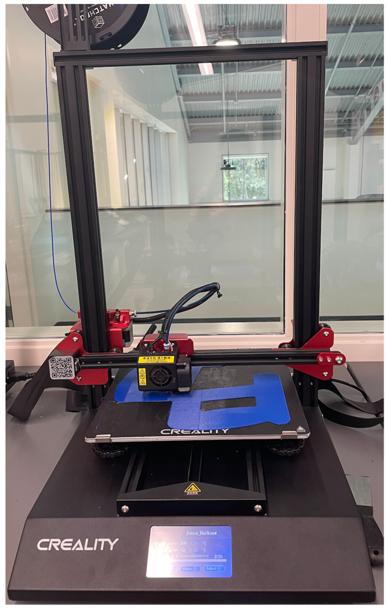
Figure 1. Example of an FDM 3D printer with a polymer filament spool (top-left).
Compared to traditional manufacturing, additive manufacturing via FDM methods is more cost effective. While the initial investment into 3D FDM printing can be substantial, its application in prototyping and part design saves both time and economic resources. On average, a 1 kg roll of Polylactic Acid (PLA) filament is approximately USD 20.00 [7]. In addition to the benefits from the lower cost of raw materials, the reduction in fabrication time and labor, as well as the close-to-zero waist of material due to no subtractive fabrication process, significantly affect the overall cost of part manufacturing compared to traditional manufacturing techniques. The type and size of a 3D printer determine the overall associated cost. An initial investment for a larger industrial-scale FDM printer is the in the range of USD 70,000 to USD 400,000. When considering smaller FDM printers such as a desktop model for mostly prototyping purposes, the initial cost could be in the range of USD 1300 to USD 2500 [8][9][10]. With the complex geometry available to manufacturers/fabricators that would be unrealistic by traditional means, FDM is the answer. The major issues posed by the increasing application of FDM additive manufacturing in comparison to traditional manufacturing are the ability to find internal defects and the assessment of the quality of the parts.
Additive manufacturing or 3D printing has been also utilized for parts built of composite materials. The combination of two materials as the base for developing composite materials has been developed over the years to achieve enhanced mechanical and material properties such as higher strength-to-weight ratios as well as thermal and/or electrical functionalities [11]. The 3D printing of composite materials comes with its own pros and cons. It provides the capability to print parts with complex geometries and controlled dimensions, but at the same time, it has certain limitations regarding the reinforcement materials that can be added to the base polymer to print a polymer matrix composite [12]. In addition, both developing composite materials by adding reinforcement particles and printing such a combination of materials can cause a certain kind of defect and anomaly generation in printed parts or the inappropriate functionality of the 3D printers [13]. Some of the major types of such defects include warping and geometrical distortion, voids and porosities in the matrix and filament, poor fiber–matrix bonding, and uneven reinforcement distribution in the matrix base polymer. As an example, the homogeneity of the reinforcing and base polymer mixing is a common challenge which can cause significant changes in composite material properties. Related common types of defects and failures of polymer and composite materials and their 3D printing are discussed in the following section.
1.2. Common Defects Posed by FDM Printing
With the large application and rapid growth of additively manufactured materials, the concern for the integrity and safety of the parts and testing methods is paramount. Unlike traditionally manufactured parts, due to the nature of the polymer-based FDM materials, traditional stress/strain tests or defect inspection tests would result in the damage and destruction of the part. Currently, the most common defects are porosity and density changes within the material [14]. This is caused by a various number of issues, but the most common is the environmental and production control of the application of thermal and humidity changes within the fabrication process [15][16].
FDM technology fabricates a part through a heating and cooling cycle of a filament. For PLA, the recommended temperature is between 401 °F +/− 27° [7]. However, the recommended temperature will vary based on the diameter of the filament and the extrusion nozzle of the printer head. The extrusion temperature is crucial in FDM printing. The temperature directly impacts the viscosity and adhesion of the filament, which are deciding factors of the functionality of the print [17]. For parts that are designed for aesthetic purposes, the issue is not a consideration. For pieces fabricated for their resultant functionality within a whole integrated system, this issue is daunting.
1.2.1. Thermal Inconsistencies Affecting Part Fabrication
The application of heat is vital in FDM for both polymer and composite printing. The process of extrusion has to be maintained throughout the printing process. Within FDM technology, the largest issue is heating consistency. There are several different types of FDM printers in circulation during the 21st century. While there is a wide variety of filament types, this entry will focus on the application of acrylonitrile butadiene styrene (ABS) and polylactic acid (PLA). In FDM printers, there are two common applications of heat. The first application of heat is within the thermocouple attached to the printer head extruder. This thermocouple is controlled by the software used by the printer. It runs using cycle heating, meaning that the thermocouple will reach the required temperature, and then the heat application will be removed until it drops to a temperature outside of the tolerance range. This lack of consistency is a reoccurring and substantial issue with FDM applications. With the inconsistent heating/cooling of the polymer filament, the adhesion of the applied layers will differentiate, causing an ununiformed density and consistency between the layers of the part.
FDM printing layer adhesion is greatly affected by the ambient temperature created by the thermocouples connected to the print bed. When in an enclosed system, the thermocouples attached to the underside of the print bed produce and maintain an average temperature. This temperature is commanded by the software of the printer per the filament requirements stated in the slicing software. Fluctuations in the print bed temperature will result in the warping of the base layer of the print. This warping will produce inconsistent prints and failures for the rest of the print. When the base layers warp, the chances of being caught on the printer extrusion head are drastically increased, and the adhesion of the print to the print bed will be jeopardized. If the filament is applied to the print bed at a temperature that increases the viscosity, the print will fail to adhere at a microlevel, therefore reducing the surface tension between the print bed and the print itself. This type of defect is very common in an exposed printer environment, mainly due to the ambient fluctuations of an uncontrolled environment.
When a print bed is heated to a temperature higher than that recommended for the print, the risk of over-melting the print and the reduction of the print bed/part adherence greatly increases. If the filament is not allowed to harden at a gradual pace, the print head will extrude filament that will not adhere to the print bed. This will result in “air printing”, or the filament extruding into the air rather than attaching to the print bed. This is a more common issue with printers that have fewer than five thermocouples and an open printing environment [18]. Printers with fewer than five thermocouples have a higher chance of cold spots and inconsistent heating due to overlapping ranges. This is because thermocouples work on an average range of temperatures rather than keeping a constant temperature. The thermocouples will fluctuate within the range, creating that average temperature reported between them. When thermocouples work, they must take into account not just the temperature ranges of the hot end but also the impact of the external environment [19].
1.2.2. Fiber-Related Defects in Composites
However, adding reinforcing materials or fibers to the base polymer has been shown to be beneficial in enhancing material properties in composites, but they can also cause several challenges in terms of defect generation and challenges with enhanced mechanical properties [20]. One of these challenges arises from the feeding material development and usage process. Mixing the fibers with the matrix polymer must be done such that the final composition is as uniform as possible. The uniformity of the composition is not only an essential factor toward the enhanced mechanical properties but also eliminates stress concentration in particular areas or weak regions in the composite material [21]. When 3D printing composite materials, it is expected to have a well-defined fiber orientation in the final part. Several different factors from both the feeding composite material and the manufacturing process may cause a local alignment deviation of fibers. Such localized misalignment of the fibers is called waviness [22]. If a composite part contains waviness flaws, it is more likely to be subjected to failure at or around the waviness regions during the strength test or over the operating life of the structure. Several studies have evaluated the waviness and its influence on mechanical properties and the failure of the composite material [23][24][25]. As explained earlier, fiber waviness, in addition to a few other factors such as manufacturing deficiency and curved geometries and coordination, can generate a related defect which is generally due to fiber misalignment [26]. Fiber misalignment is particularly important in unidirectional composite materials and is shown to have a significant effect on the mechanical properties of the composite materials [27]. In a fiber-reinforced polymer composite, fibers are considered to be the main load-bearing component of the material. Due to the important role of fibers in the structural integrity of composite materials, fiber breakage has a significant effect on the overall strength and toughness of the composite parts [28]. Since the fiber breakage is a distributed type of defect in composite materials, both the localized and overall effect of these defects must be investigated and assessed for a load-bearing composite part susceptible to fiber breakage flaws [29].
Figure 2 shows the common defects and faults in parts and machines posed by the FDM printing of polymers and composites, which are described in the following sections.
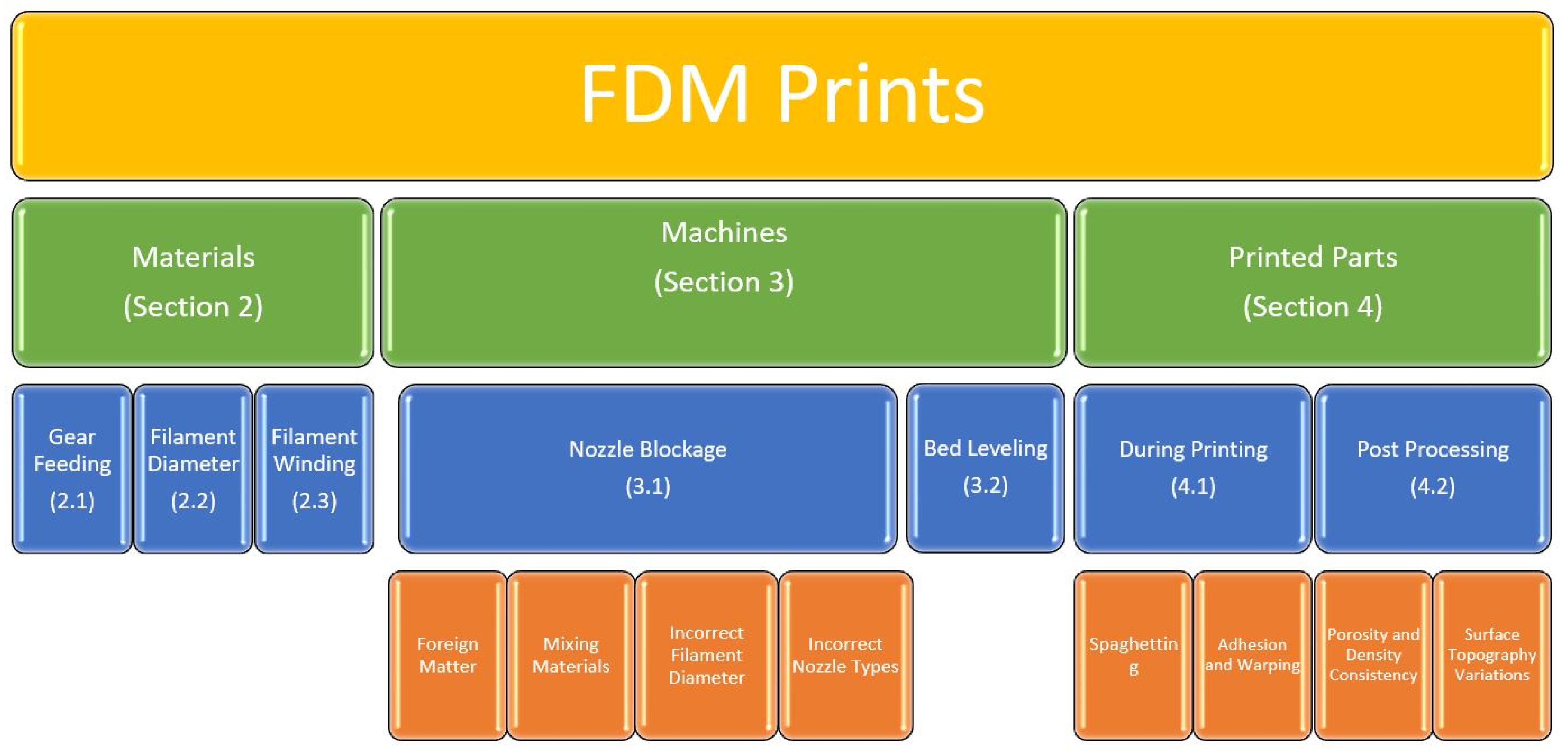
Figure 2. Common defects posed by the FDM printing of polymers and composites.
2. Nondestructive Testing (NDT) Methods
Nondestructive Testing (NDT) Applications are a large asset to Additive Manufacturing Engineering [30][31][32][33][34]. Due to the time-consuming nature and recyclability of most filaments, any traditional integrity and safety testing of parts would render the printed part unusable.
2.1. Nondestructive Testing in the Process
Temperature and thermal signatures monitoring has been widely used for the in-process quality monitoring of machines and parts. These techniques are commonly being applied through two main methods. The first method is based on temperature measurement with traditional or advanced thermocouple sensors. Thermocouples are used to measure the temperature of critical parts or locations during the 3D printing processes including bed or base plate temperature, nozzle temperature, and filament temperature. If the measurement is conducted on the machine parts such as the nozzle, the goal is usually to monitor the health of the machine for smooth operation. Temperature measurement is also conducted on the parts over the printing process. In this case, the goal is usually to monitor the integrity of the part and correlate the measurement to the potential flaws and defects. As an example, a large temperature gradient or shock usually causes cracking of the printed parts, which propagate even after the printing is completed or over the operational lifetime of the parts. The second thermal-based method for quality monitoring is based on thermal imaging using thermal cameras. Thermal cameras are devices that work based on capturing the thermal emissions from the objects and recording an image or a video on their detector. Based on the type and working mechanism of the thermal cameras, the temporal and spatial resolution of the recorded image and/or video, as well as their speed and resolutions, might be different, which is an important factor in using these devices for the in situ monitoring of 3D printing. Thermal imaging will detect the thermal inconsistencies within the part in real time, communicate with the operator, and allow them to adjust the process accordingly [11][35][36][37][38]. This will assist in a more uniform print, thus reducing density and layer adhesion inconsistencies. Depending on the extruded temperature of the filament, the rigidity and porosity are subject to change. Upon the extrusion temperature being above the recommended ranges of the filament, the viscosity of the filament will reduce, resulting in an unstable filament extrusion. This will produce a layer that will spread unnecessarily and fuse incorrectly to the rest of the print. The porosity and thickness of the layer will also be affected. In the instance where the extrusion temperature is lower than that of the recommended temperature, the viscosity of the filament will be higher than the suggested levels. This will result in a thicker and denser layer, causing improper bonding between layers. This porosity can be visualized either through the above-mentioned thermal imaging or even by a laser profilometer [35][39]. The laser profilometer would measure the amount of polymer that fills each layer. If the laser profilometer was used to detect under- or over-filled lower layers, that detection would cause the upper layers to compensate so that the final product would become smooth. This would, of course, depend on the adhesion between the layers. A way to alleviate the inconsistent heating between the thermocouples and the print bed is to use the skirt adhesion type build plate [40]. It was found in a study conducted by Nguyen et al. that the adhesion type was the most significant parameter tested that affected the vibrational response of the print. This change from raft to skirt adhesion has been shown to result in better inter-layer fusion and increased heat consistency, which in turn yields a better polymer print.
Layer-wise quality monitoring over the printing process through imaging techniques can also be done using optical images. In this method, optical cameras with a sufficient resolution and sensitivity are used to capture images on each layer during the fabrication process. Such an image will then be compared to the information from the G-code of the part’s model for the automatic detection of the flaws and anomalies in the layer. Optical camera integration usually costs less than thermal cameras and is easier to integrate and operate. Computer vision algorithms are effective techniques for analyzing the images and extracting the information from them.
Shmueli et al. described in their paper that thermal imaging can be used during the 3D printing process, and X-ray scattering can also be used during that time. The X-ray scattering was shown to be indicative of the overall strength of the composite. This indication was given by the measured crystallinity of the polymer layer. Depending on the orientation of the molecules within the layers, the determination of the brittleness was shown to be directly correlated with the overall crystallinity of the composite [37][41]. X-rays are an efficient technique for the inspection of the 3D-printed parts, specifically for the assessment of the internal structure and volumetric flaw detection. Higher initial costs of the equipment and operation, safety concerns, higher technical skills requirements, and the complexity of the integration into the 3D printing machine are the major factors that limit the application of X-rays for in-process quality monitoring. This is even more critical for the 3D printing of polymers and composites since there might be less of a chance for cost justification.
The application of the NDT during the production process of the part would then allow for a layer-by-layer account of the part, since layer-wise enables the in situ monitoring of the process for each individual layer if the proper sensor(s) are integrated into the system.
2.2. Nondestructive Testing after the Process
After the completion of the printing process, the finished parts can be inspected for quality and potential flaws using various NDT techniques depending on the material, geometrical, and surface conditions. Ultrasonic, radiography, thermography, and microwave NDT are among the most applicable inspection techniques for polymer and composite materials. The above-mentioned uniformity issue can be detected using phase array ultrasound technology (PAUT), producing an image for the engineers to view without destroying the part to detect defects within the part [42][43][44]. PAUT used an array of an ultrasonic transducer to send and receive ultrasonic waves into the part in an electronically programmed sequence. Within the ultrasound, the largest issue is the conduction of the projected frequencies through the air and into the part. Due to the layering texture of the produced parts or their surface condition, it is highly difficult to produce a perfectly flush surface mating [45]. The surface irregularities produce “noise”, the detection of frequencies due to air, thus reducing the accuracy of the ultrasonic testing technology. To limit the feedback noise from the irregular surface, the use of media or a controlled AM part is needed. As of now, the largest issue is the absence of a piece that adapts to the changing surface texture of the part and remains solid for the sensor to rest on. To solve this issue, additive manufacturing could be the answer. A controlled AM part would need to fit the surface texture and fill in the ridges and valleys produced by FDM. A promising way to negate those effects would be to use stereolithography (SLA) printing combining a rigid and semi-aqueous resin material [46][47][48].
The produced part would then act as a conductor between the sensor and the FDM part. A series of control tests using the ultrasound sensor and AM medium need to be conducted to allow for the removal of any potential noise remaining and effectively “zero” the sensor out for the testing application of the FDM part. The rigid resin portion of the mating piece would act as a sturdy, flush surface for the sensor to rest on. This would reduce the amount of noise feedback caused by air and ambient vibrations. The semi-aqueous resin material would then shape and form to the ridges and valleys of the part to test. This would again limit the noise produced by the air and ambient vibrations. To further reduce unwanted feedback, using a jelly medium would further increase the surface contact and produce a physical pathway for the ultrasound waves to penetrate the parts.
The media described above for surface mating techniques would then allow for the flat-bottomed sensors to be used on a larger variety of AM geometry parts. One of the largest concerns of using ultrasound technology is the complex geometry allowance provided by AM production technology, mainly within FDM. These issues are mainly focused on complex internal geometry. However, in using surface mating techniques and applying NDT methods to several faces, the ultrasound readings could effectively produce a 3D image of the part in question. This would then allow the researcher to break the part down to a layer level and detect where any defects occurred when compared to the digital slicing software layer models [49][50].
Radiography testing (RT) is always a reliable NDT technique for the post-process evaluation of the parts. For polymers and composites, RT faces less of a challenge regarding the penetration into these materials, since they are much less dense when compared to the metals and ceramics. Due to this characteristic, RT can penetrate into considerably thick parts of polymers and composites without being limited by the surface condition or geometry of the part. Then, the whole internal structure of the parts can be visually imaged in a 3D image using computed tomography (CT) or just in conventional 2D X-ray images. Similar to other imaging techniques, image processing (in 2D and 3D RT) and image reconstruction techniques (in 3D or CT imaging) are crucial to obtaining accurate measurements and information from the RT. The dependency of the RT images on the angle of projection is a major issue in 2D X-ray images. If a flaw has a very high aspect ratio, e.g., a long line or crack type, then it may be projected very well in an angle perpendicular to the projection plane, but it might be totally missed in the other 90-degree perpendicular view. However, this is a less important issue if a 3D CT image is produced, which takes more time and will have a larger size.
References
- Gibson, I.; Rosen, D.; Stucker, B.; Khorasani, M. Additive Manufacturing Technologies; Springer: Cham, Switzerland, 2020.
- Groover, M.P. Fundamentals of Modern Manufacturing; Wiley: Hoboken, NJ, USA, 2022.
- Zhao, H.; Liu, X.; Zhao, W.; Wang, G.; Liu, B. An Overview of Research on FDM 3D Printing Process of Continuous Fiber Reinforced Composites. In Journal of Physics: Conference Series; IOP Publishing: Bristol, UK, 2019; p. 052037.
- Pervaiz, S.; Qureshi, T.A.; Kashwani, G.; Kannan, S. 3D Printing of Fiber-Reinforced Plastic Composites Using Fused Deposition Modeling: A Status Review. Materials 2021, 14, 4520.
- Singh, R.; Singh, S.; Mankotia, K. Development of ABS Based Wire as Feedstock Filament of FDM for Industrial Applications. Rapid Prototyp. J. 2016, 22, 300–310.
- Albakri, M.I.; Sturm, L.D.; Williams, C.B.; Tarazaga, P.A. Impedance-based non-destructive evaluation of additively manufactured parts. Rapid Prototyp. J. 2017, 23, 589–601.
- Matterhackers. Available online: https://www.matterhackers.com/ (accessed on 6 December 2021).
- Makerbot Replicator. Available online: http://store.makerbot.com/replicator (accessed on 6 December 2021).
- Makerbot Replicator Mini. Available online: http://store.makerbot.com/replicator-mini (accessed on 6 December 2021).
- Cubify Cube Store. Available online: http://cubify.com/cube/store.aspx (accessed on 6 December 2021).
- Wickramasinghe, S.; Do, T.; Tran, P. FDM-Based 3D Printing of Polymer and Associated Composite: A Review on Mechanical Properties, Defects and Treatments. Polymer 2020, 12, 1529.
- Blanco, I. The use of composite materials in 3D printing. J. Compos. Sci. 2020, 4, 42.
- Kalsoom, U.; Nesterenko, P.N.; Paull, B. Recent developments in 3D printable composite materials. RSC Adv. 2016, 6, 60355–60371.
- Triyono, J.; Sukanto, H.; Saputra, R.M.; Smaradhana, D.F. The effect of nozzle hole diameter of 3D printing on porosity and tensile strength parts using polylactic acid material. Open Eng. 2020, 10, 762–768.
- Bhagia, S.; Bornani, K.; Agrawal, R.; Satlewal, A.; Ďurkovič, J.; Lagaňa, R.; Bhagia, M.; Yoo, C.G.; Zhao, X.; Kunc, V.; et al. Critical review of FDM 3D printing of PLA biocomposites filled with biomass resources, characterization, biodegradability, upcycling and opportunities for biorefineries. Appl. Mater. Today 2021, 24, 101078.
- Swetham, T.; Reddy, K.M.M.; Huggi, A.; Kumar, M.N. A Critical Review on of 3D Printing Materials and Details of Materials Used in FDM. Int. J. Sci. Res. Sci. Eng. Technol. 2017, 3, 353–361.
- Zhu, Q.; Yu, K.; Li, H.Q.; Zhang, Q.Q.; Tu, D.W. Rapid residual stress prediction and feedback control during fused deposition modeling of PLA. Int. J. Adv. Manuf. Technol. 2022, 118, 3229–3240.
- Kuo, C.C.; Wu, Y.R.; Li, M.H.; Wu, H.W. Minimizing warpage of ABS prototypes built with low-cost fused deposition modeling machine using developed closed-chamber and optimal process parameters. Int. J. Adv. Manuf. Technol. 2019, 101, 593–602.
- Nazan, M.A.; Ramli, F.R.; Alkahari, M.R.; Abdullah, M.A.; Sudin, M.N. An exploration of polymer adhesion on 3D printer bed. IOP Conf. Ser. Mater. Sci. Eng. 2017, 210, 012062.
- Taheri, H. Utilization of Non-destructive Testing (NDT) Methods for Composite Materials Inspection (Phased Array Ultrasonic). Master’s Thesis, South Dakota State University, Brookings, SD, USA, 2014.
- Lin, T.; Jia, D.; He, P.; Wang, M.; Liang, D. Effects of fiber length on mechanical properties and fracture behavior of short carbon fiber reinforced geopolymer matrix composites. Mater. Sci. Eng. A 2008, 497, 181–185.
- Alves, M.; Junior, C.C.; Ha, S. Fiber waviness and its effect on the mechanical performance of fiber reinforced polymer composites: An enhanced review. Compos. Part A Appl. Sci. Manuf. 2021, 149, 106526.
- Senthil, K.; Arockiarajan, A.; Palaninathan, R.; Santhosh, B.; Usha, K. Defects in composite structures: Its effects and prediction methods–A comprehensive review. Compos. Struct. 2013, 106, 139–149.
- Kugler, D.; Moon, T.J. Identification of the most significant processing parameters on the development of fiber waviness in thin laminates. J. Compos. Mater. 2002, 36, 1451–1479.
- Thor, M.; Sause, M.G.; Hinterhölzl, R.M. Mechanisms of origin and classification of out-of-plane fiber waviness in composite materials—A review. J. Compos. Sci. 2020, 4, 130.
- Bednarcyk, B.A.; Aboudi, J.; Arnold, S.M. The effect of general statistical fiber misalignment on predicted damage initiation in composites. Compos. Part B Eng. 2014, 66, 97–108.
- Li, Y.; Stier, B.; Bednarcyk, B.; Simon, J.-W.; Reese, S. The effect of fiber misalignment on the homogenized properties of unidirectional fiber reinforced composites. Mech. Mater. 2016, 92, 261–274.
- Kidangan, R.T.; Krishnamurthy, C.V.; Balasubramaniam, K. Identification of the fiber breakage orientation in carbon fiber reinforced polymer composites using induction thermography. NDT E Int. 2021, 122, 102498.
- Liu, T.; Gao, Y.; Fan, W.; Gao, X.; Ma, J. Predictions of the axial tensile property of the unidirectional composite influenced by microfiber breakage defects. Text. Res. J. 2022, 92, 15–29.
- Taheri, H. Nondestructive Evaluation and In-Situ Monitoring for Metal Additive Manufacturing. Ph.D. Thesis, Iowa State University, Ames, IA, USA, 2018; pp. 61–75.
- Koester, L.W.; Bond, L.J.; Taheri, H.; Collins, P.C. Nondestructive Evaluation of Additively Manufactured Metallic Parts. Nondestruct. Eval. Mater. 2018, 17, 544–552.
- Koester, L.W.; Bond, L.J.; Taheri, H.; Peter CCollins, P.C. Nondestructive evaluation of additively manufactured metallic parts: In situ and post deposition. In Additive Manufacturing for the Aerospace Industry; Elsevier Inc.: Philadelphia, PA, USA, 2018; Chapter 18; pp. 401–417.
- Koester, L.W.; Taheri, H.; Bigelow, T.; Collins, P.C.; Bond, L.J. Nondestructive Testing for Metal Parts Fabricated Using Powder-Based Additive Manufacturing. Mater. Eval. 2018, 76, 514–528.
- Koester, L.W.; Taheri, H.; Bond, L.J.; Barnard, D.; Gray, J. Additive manufacturing metrology: State of the art and needs assessment. In AIP Conference Proceedings; AIP Publishing LLC: Melville, NY, USA, 2016; p. 130001.
- Borish, M.; Post, B.K.; Roschli, A.; Chesser, P.C.; Love, L.J. Real-Time Defect Correction in Large-Scale Polymer Additive Manufacturing via Thermal Imaging and Laser Profilometer. Procedia. Manuf. 2020, 48, 625–633.
- Sauerbrunn, E.; Chen, Y.; Didion, J.; Yu, M.; Smela, E.; Bruck, H.A. Thermal imaging using polymer nanocomposite temperature sensors. Phys. Status Solidi. (A) 2015, 212, 2239–2245.
- Shmueli, Y.; Jiang, J.; Zhou, Y.; Xue, Y.; Chang, C.; Yuan, G.; Satija, S.K.; Lee, S.; Nam, C.; Kim, T.; et al. Simultaneous In Situ X-ray Scattering and Infrared Imaging of Polymer Extrusion in Additive Manufacturing. ACS Appl. Polym. Mater. 2019, 1, 1559–1567.
- Abdelrahman, M.; Starr, T.L. Quality certification and control of polymer laser sintering: Layerwise temperature monitoring using thermal imaging. Int. J. Adv. Manuf. Technol. 2016, 84, 831–842.
- Giesko, T.; Zbrowski, A.; Czajka, P. Laser Profilometers for Surface Inspection and Profile Measurement. Probl. Eksploat. 2007, 97–108.
- Nguyen, H.T.; Crittenden, K.; Weiss, L.; Bardaweel, H. Experimental Modal Analysis and Characterization of Additively Manufactured Polymers. Polymer 2022, 14, 2071.
- Liao, Y.; Liu, C.; Coppola, B.; Barra, G.; Di Maio, L.; Incarnato, L.; Lafdi, K. Effect of Porosity and Crystallinity on 3D Printed PLA Properties. Polymer 2019, 11, 1487.
- Taheri, H.; Du, J.; Delfanian, F. Experimental Observation of Phased Array Guided Wave Application in Composite Materials. Mater. Eval. 2017, 75, 1308–1316.
- Taheri, H.; Hassen, A.A. Nondestructive Ultrasonic Inspection of Composite Materials: A Comparative Advantage of Phased Array Ultrasonic. Appl. Sci. 2019, 9, 1628.
- Lee, J.; Hasanian, M.; Saboonchi, H.; Baechle, M.; Taheri, H. Ultrasonic evaluation of polymer additively manufactured parts for defect inspection and structural integrity assessment. In Nondestructive Characterization and Monitoring of Advanced Materials, Aerospace, Civil Infrastructure, and Transportation IX, 4; SPIE proceeding; SPIE Press: Bellingham, WA, USA, 2020; p. 70.
- Taheri, H.; Koester, L.; Bigelow, T.; Bond, L.J.; Braconnier, D.; Carcreff, E.; Dao, G.; Caulder, A.; Hassen, A.A. Fast Ultrasonic Imaging with Total Focusing Method (TFM) for Inspection of Additively Manufactured Polymer Composite Component. In Proceedings of the ASNT 27th Annual Research Symposium Proceedings, 10, Houston, TX, USA, 29–31 October 2018; pp. 212–220.
- Finnes, T. High Definition 3D Printing-Comparing SLA nad FDM Printing Technologies. J. Undergrad. Res. 2015, 13, 10–26.
- Kafle, A.; Luis, E.; Silwal, R.; Pan, H.M.; Shrestha, P.L.; Bastola, A.K. 3D/4D Printing of Polymers: Fused Deposition Modelling (FDM), Selective Laser Sintering (SLS), and Stereolithography (SLA). Polymer 2021, 13, 3101.
- Szykiedans, K.; Credo, W. Mechanical Properties of FDM and SLA Low-cost 3-D Prints. Procedia Eng. 2016, 136, 257–262.
- Bond, L.J.; Koester, L.W.; Taheri, H. NDE in-process for metal parts fabricated using powder based additive manufacturing. In Smart Structures and NDE for Energy Systems and Industry 4.0, 3; SPIE proceeding; SPIE Press: Bellingham, WA, USA, 2019; p. 1.
- Taheri, H.; Koester, L.W.; Bigelow, T.A.; Faierson, E.J.; Bond, L.J. In Situ Additive Manufacturing Process Monitoring With an Acoustic Technique: Clustering Performance Evaluation Using K-Means Algorithm. J. Manuf. Sci. Eng. 2019, 141, 041011.
More
Information
Subjects:
Engineering, Manufacturing
Contributors
MDPI registered users' name will be linked to their SciProfiles pages. To register with us, please refer to https://encyclopedia.pub/register
:
View Times:
1.3K
Revisions:
2 times
(View History)
Update Date:
13 Jul 2022
Table of Contents


Notice
You are not a member of the advisory board for this topic. If you want to update advisory board member profile, please contact office@encyclopedia.pub.
OK
Confirm
Only members of the Encyclopedia advisory board for this topic are allowed to note entries. Would you like to become an advisory board member of the Encyclopedia?
Yes
No
${ textCharacter }/${ maxCharacter }
Submit
Cancel
Back
Comments
${ item }
|
${ item.createdUser.fullName }
${ item.createdAt }
${ item.vote }
${ item.reply }
Delete
${ reply.createdUser.fullName }
${ reply.createdAt }
${ reply.vote }
Delete
There is no reply to this comment~
${ item.replyTextCharacter }/${ item.replyMaxCharacter }
Submit
Cancel
More
No more~
There is no comment~
${ textCharacter }/${ maxCharacter }
Submit
Cancel
${ selectedItem.replyTextCharacter }/${ selectedItem.replyMaxCharacter }
Submit
Cancel
Confirm
Are you sure to Delete?
Yes
No