Your browser does not fully support modern features. Please upgrade for a smoother experience.
Submitted Successfully!
 +1 credit
Thank you for your contribution! You can also upload a video entry or images related to this topic.
For video creation, please contact our Academic Video Service.
| Version | Summary | Created by | Modification | Content Size | Created at | Operation |
|---|---|---|---|---|---|---|
| 1 | Paulo Branco | -- | 2336 | 2022-07-11 22:34:31 | | | |
| 2 | Sirius Huang | Meta information modification | 2336 | 2022-07-12 03:40:07 | | |
Video Upload Options
We provide professional Academic Video Service to translate complex research into visually appealing presentations. Would you like to try it?
Cite
If you have any further questions, please contact Encyclopedia Editorial Office.
Costa, J.V.; Silva, D.F.F.D.; Branco, P.J.C. Abnormal Operating Conditions of Oil-Immersed Large Power Transformers. Encyclopedia. Available online: https://encyclopedia.pub/entry/25023 (accessed on 24 July 2026).
Costa JV, Silva DFFD, Branco PJC. Abnormal Operating Conditions of Oil-Immersed Large Power Transformers. Encyclopedia. Available at: https://encyclopedia.pub/entry/25023. Accessed July 24, 2026.
Costa, Jonathan Velasco, Diogo F. F. Da Silva, Paulo J. Costa Branco. "Abnormal Operating Conditions of Oil-Immersed Large Power Transformers" Encyclopedia, https://encyclopedia.pub/entry/25023 (accessed July 24, 2026).
Costa, J.V., Silva, D.F.F.D., & Branco, P.J.C. (2022, July 11). Abnormal Operating Conditions of Oil-Immersed Large Power Transformers. In Encyclopedia. https://encyclopedia.pub/entry/25023
Costa, Jonathan Velasco, et al. "Abnormal Operating Conditions of Oil-Immersed Large Power Transformers." Encyclopedia. Web. 11 July, 2022.
Copy Citation
Large power transformers (LPT) are custom-built pieces of equipment that are crucial links to the bulk transmission grid. Usually, they link a generator-transmission line and/or linking lines of different voltages. It is essential for large power transformers to understand which condition of their components indicates an abnormal operation.
large power transformer
condition monitoring
transformer fault diagnosis
1. Introduction
In the current context of deregulation of electricity systems, each electricity company seeks to manage its assets more efficiently, basing itself on conditional and proactive maintenance methodologies. This pursues to limit the number of interruptions in the grid and thus avoid economic penalties that can be severe. More specifically, only one large power transformer’s shutdown can lead to direct and indirect losses that would far exceed its price [1].
It is even more essential for large power transformers to understand which condition of their components indicates an abnormal operation. To systematize this point, it is shown in Figure 1 a drawing cut of a typical large power transformer and its main components. The potential and associated abnormal conditions are presented based on those identified.
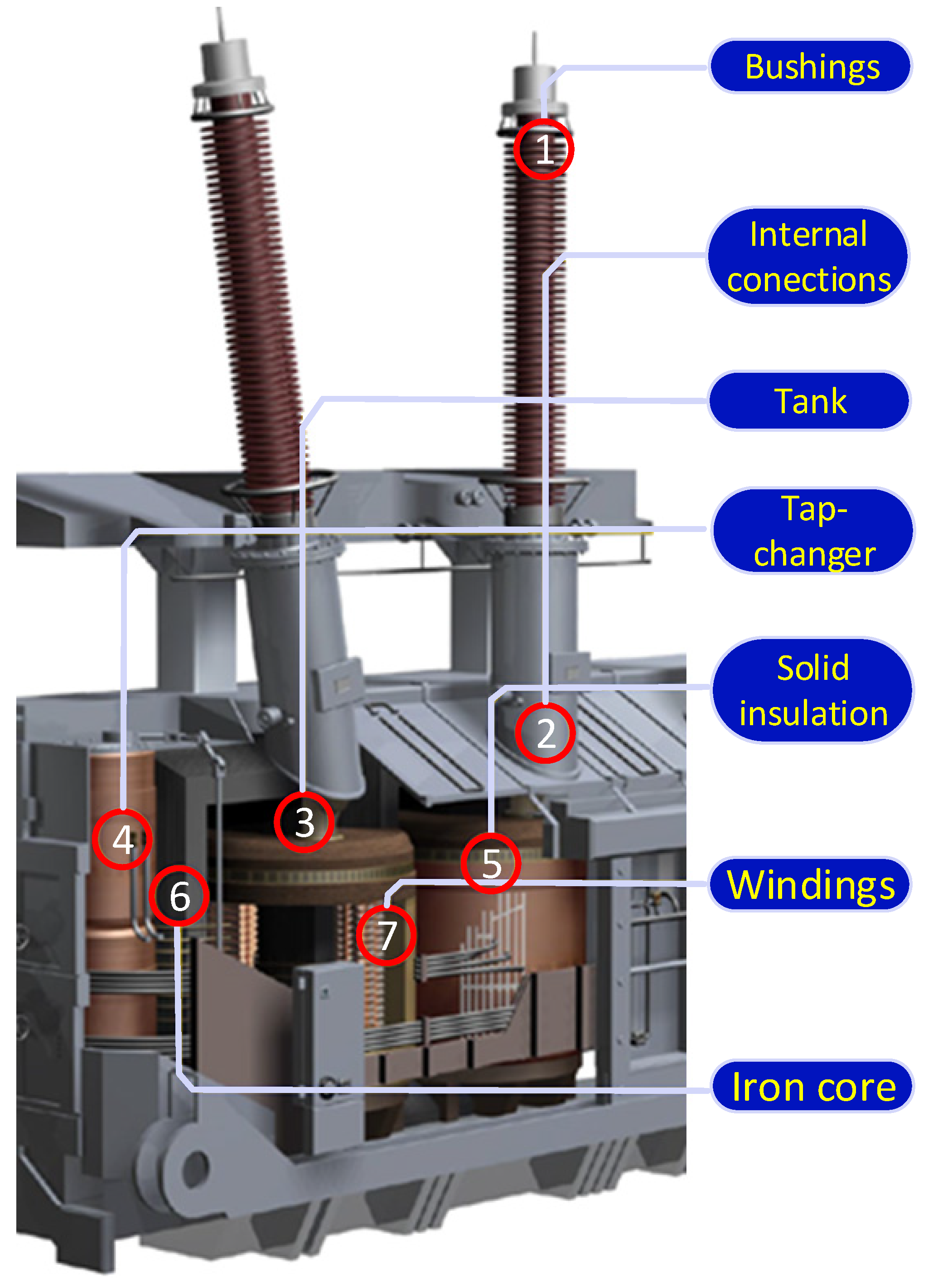
Figure 1. A large power transformer and its main components.
2. Active Part
2.1. Windings
The windings’ abnormal operating conditions are one of the most frequent causes of failures, for they can experience wear at the mechanical, thermal, and dielectric levels [2]. These three always appear in a coupled way, and, most often, one of the phenomena proves to be more significant for the appearance of failure.
Mechanical anomalies are the windings’ loosening, displacement, or deformation [3][4], as shown in Figure 2a. These anomalies originate from improper repair, poor maintenance, corrosion, manufacturing defects, vibrations, and mechanical displacements within the transformer. On the other side, windings can present high thermal losses in events such as a short circuit in the outer terminals. These losses usually give rise to “hot spots” that can lead to small ruptures or even the total copper breaking in the windings.
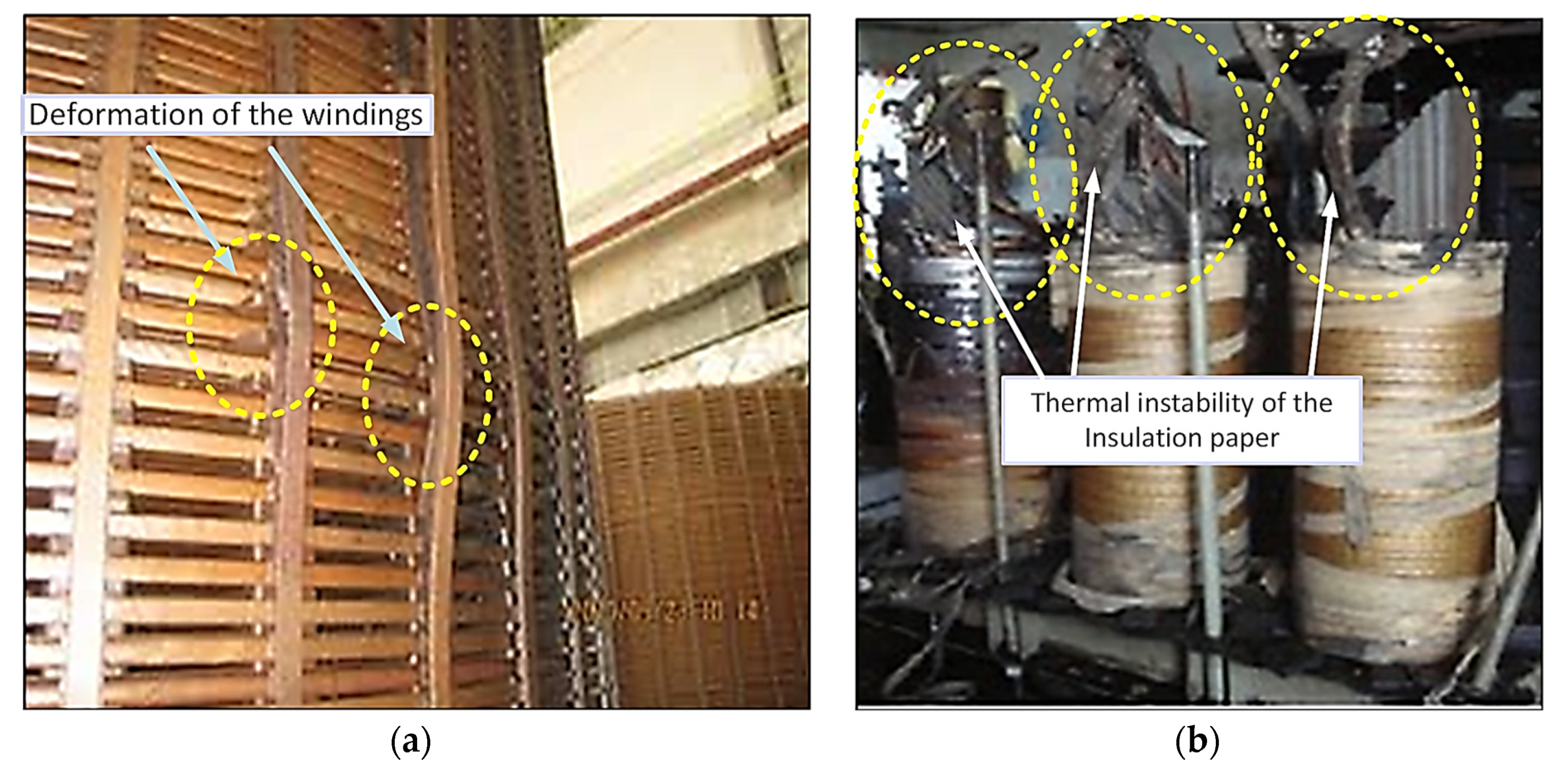
Dielectric anomalies come from disruptions of the insulating material between phases. Disruption occurs due to high potential differences such that the resulting electric field causes ruptures within the dielectric material. These can occur between turns of the same phase or between phases. Often, disruption will result in the appearance of small, short circuits that will lead to local burning of the windings [5], as shown in Figure 2b.
2.2. Transformer Core
One of the most frequent defects in the core [6] is shown in Figure 3. The displacement of the core blades due to electromagnetic forces is verified due to high eddy currents that circulated in them. In this situation, each conductor (blade) with an induced current produces a magnetic field that, when interacting with the currents circulating in the opposite blade, provokes electromagnetic forces in it, which causes a deformation in the plates [3]. Figure 4 shows an illustration of this phenomenon. If the laminations presented induced currents circulating in opposite directions, this would cause the appearance of repulsive electromagnetic forces, as in Figure 3, otherwise appear attractive forces between laminated sheets.
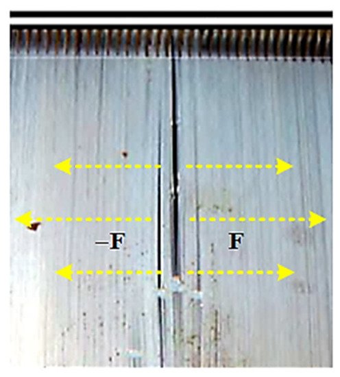
Figure 3. Illustration of a power transformer case presenting mechanical deformation of the core and laminated electrical sheets [5].
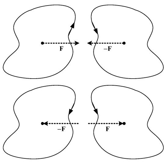
Figure 4. Illustration of forces according to the current direction.
3. Insulation System
3.1. Solid Insulation
Solid insulation is based on cellulose, namely paper and pressed wooden impregnated with oil forming a dielectric and mechanical insulation of the windings. The abnormal operating conditions that arise in these elements result mainly from the degradation of cellulose. The degradation has three mechanisms as its basis: hydrolysis (decomposition of the chemical compound by reaction with water), pyrolysis (decomposition or transformation of the compound by the action of heat), and oxygenation (combination of a substance with oxygen) [7]. The hydrolysis phenomenon is the mechanism that contributes most to the breakdown of the long chains of glucose rings that make up cellulose. This degradation and aging of cellulose significantly contribute to the loss of dielectric and mechanical properties that lead, for example, to short circuits between windings.
3.2. Liquid Insulation
The dielectric fluid has two objectives: insulating the transformer core and its tank and cooling the transformer by convection. The oil circulates through the main tank, absorbed by the paper (helps its cooling), giving it special dielectric characteristics. Oil circulation also allows the removal of heat from the core to the environment, as the oil, when heating, rises and enters the pipe that leads to the radiator.
The quality of the used oil greatly affects the properties of the insulation and cooling systems as particles (water, rust, and acids) appear in it due to its aging [8][9]. These make the oil more viscous, making its circulation difficult, thus risking the transformer’s cooling capacity. If these particles are electrical conductors, such as water, they can facilitate short-circuits between elements, representing a failure of the insulation system.
4. Components and Accessories
4.1. Bushings
Another type of transformer anomaly occurs in their bushings (Figure 5), which serve as insulation between the passage of the outer conductors and the interior connection to the windings; they act as a path for each stage’s current through the walls of the tank.
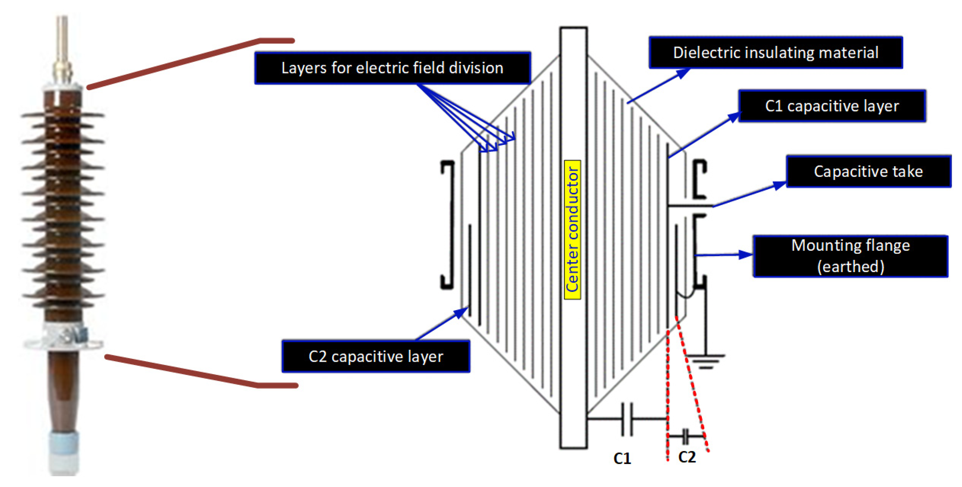
Figure 5. OIP bushing and capacitive bushings scheme.
The bushings can be of the capacitive or non-capacitive type, and for transformers, with higher operating voltages, it is usual to use the capacitive type bushings (Figure 5). Capacitive type bushings are classified as “OIP” (Oil Impregnated Paper—layers of oil-impregnated paper), “RIP” (Resin Impregnated Paper—paper impregnated with epoxy resins), and “RBP” (Resin Bonded Paper—layers of Bakelitized paper), the manufacture of the latter being practically abandoned due to problems related to partial discharges [10].
In Figure 5 left, it is possible to visualize an OIP bushing, and in Figure 5 right, it represents its scheme. The bushing is composed of a central conductor covered with paper impregnated in oil or resin (considering only the bushings of the OIP and RIP type) and the external insulator, usually in porcelain. The bushing is represented by a center conductor and several condensers between this and the mounting flange, as represented in its diagram in Figure 5, right side. Between the central conductor and the capacitive tap (where measurements are taken), there is the capacitor C1, which represents the value of the total capacitance in series resulting from the different layers of electric potential distribution. The capacitor C2 translates the capacitance value between the capacitive layer C2 and the capacitive tap; it corresponds to the insulation between C1 and the mounting flange [11].
Degradation of bushings, mainly those located at the high-voltage side, is reflected in the appearance of partial discharges and the loss of dielectric properties that will lead to overheating, as illustrated in Figure 6. This degradation may be due to the following set of factors:
-
Contamination of insulators, due to deposition of contaminants (water, dust) on the surface of bushings [12] and, for highly polluted places, they must be washed regularly;
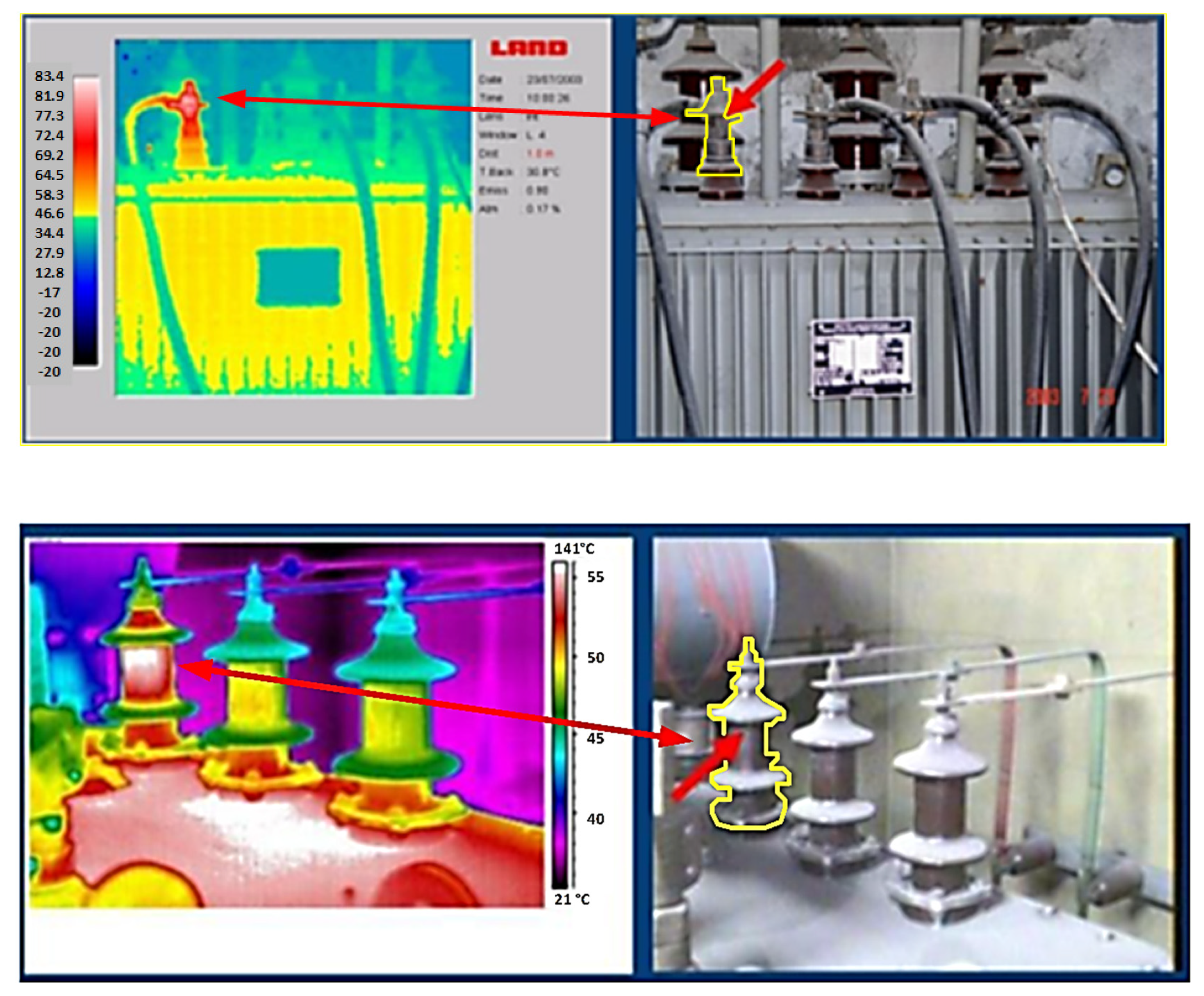
Figure 6. Thermographic photographs of overheating bushings [17].
4.2. Tap-Changer
Tap-changer is one of the most critical components of a large power transformer [18] as it is one of the only that exhibits a controlled displacement (Figure 7a). It can regulate the voltage and/or phase change by varying the ratio of the number of turns of the transformer without interrupting the load, thus compensating for constant load variations. There are two types of tap-changers: those using resistors or reactances during the switching process. The first is installed inside the tank (they can have their oil or share it), while the second is usually welded to the tank [19]. In Europe, resistive-type tap-changers are generally used.
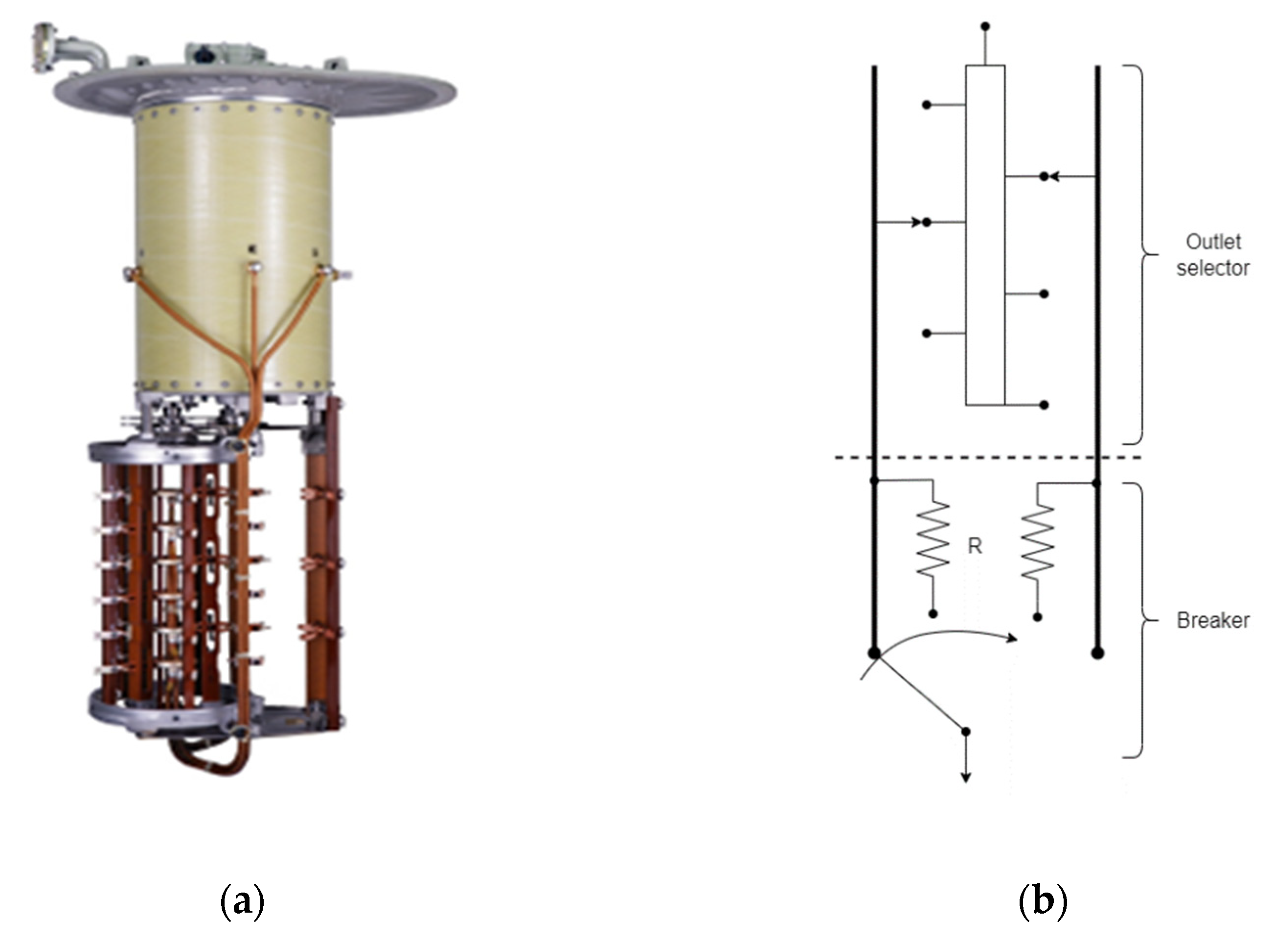
Figure 7. On-load tap-changer. (a) tap-changer device commercially available; (b) diagram of the tap-changer working principle.
The tap-changer comprises a “switch” switching component and a “plug selector” selection component, as illustrated in Figure 7b. The entire switching process is driven by a single-phase induction motor placed outside the transformer.
Variation of the number of turns ratio is intended to be carried out without interrupting the load current. The process always occurs by connecting the next socket before undoing the previous connection. To avoid the high current coming from the short circuit between turns, a transition impedance is inserted in the form of electrical resistance or reactance, thus transferring the load current from one socket to the other.
In the on-load voltage regulator, abnormal operating conditions may also arise, which will be reflected in the operation of the transformer. Some of them are presented below.
-
Old or burnt condensers in the induction motor can lead to a loss of control in the direction of governor movement or even cause the governor motor to stop and make it impossible to change the number of turns ratio;
-
With frequent use, commutator springs lose elasticity and may even break. In this case, it will not be possible to change the ratio of the number of turns of the regulator [22];
-
The voltage regulator is frequently used, which leads to wear of the entire switching mechanism [8], especially in the contacts responsible for the transition of plugs, which are subject to electric arcs. In the on-load voltage regulator, the current interruption leads to the appearance of an electric arc, which leads to the formation of gases that are the same as those that appear in the main transformer tank due to dielectric failures. As such, if the tank is shared, false conclusions about dielectric failures and their location can result;
-
When operating on the same contact for a long time, there is a risk of deposition of carbon particles, which can char due to the heat from the increased contact resistance. In extreme cases, as shown in Figure 8a, the contacts’ carbonization leads to the impossibility of operation as the contacts are stuck [23]. This anomaly is not very common in on-load voltage regulators and is more relevant for no-load voltage regulators.
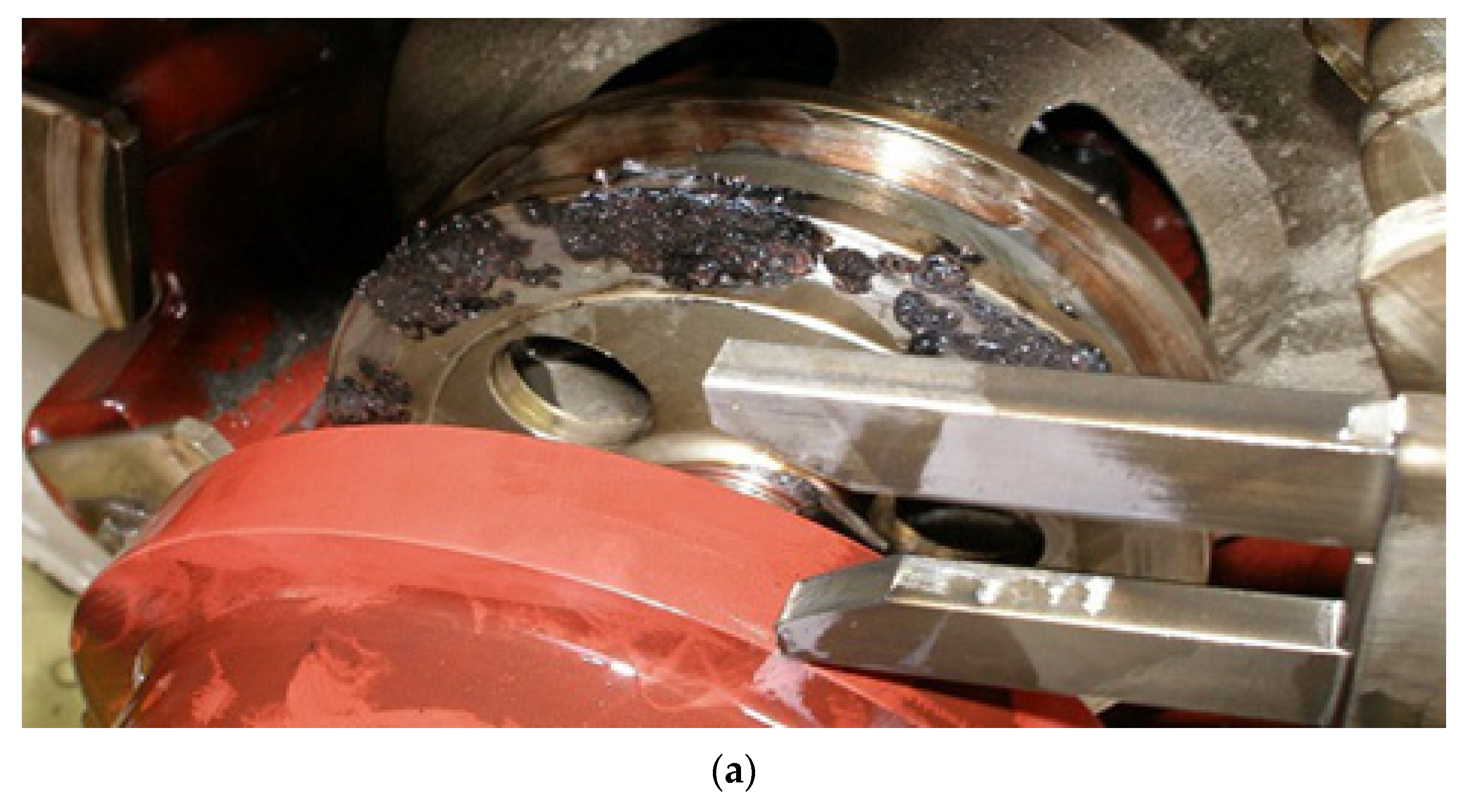
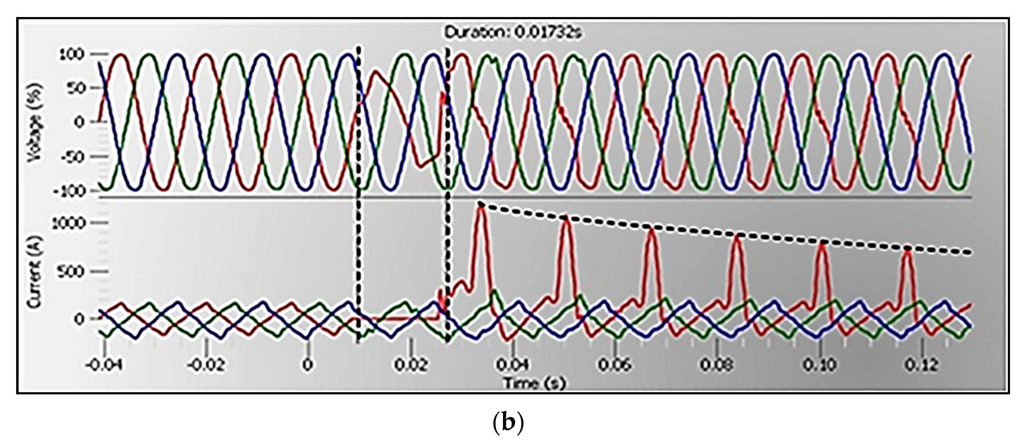
Figure 8. Abnormal condition in the on-load tap-changer (a) and current and voltage signals at the transformer terminals (b) [23].
The example illustrated in Figure 8a occurred in a substation transformer and showed the occurrence of a severe failure in the regulator switch. As can be seen from the evolution of voltages and currents at the transformer terminals in Figure 8b, the fault was reflected in the signals by the appearance of oscillations in one of the currents and the deformation associated with the respective voltage.
4.3. Tank
The tank contains the oil and provides physical protection and support for the different components of the transformer, besides ensuring the grounding of the magnetic circuit and the various metal parts. The tank may show cracks [24], essentially resulting from environmental wear and tear, such as those resulting from corrosive environments, high humidity, vibrations, and solar radiation. The tank walls may also rupture due to high-pressure gases resulting from internal arcs that vaporize the oil [25].
4.4. Cooling System
In a large power transformer, cooling is achieved through the forced circulation of oil, water, or air. Forced circulation is based on the use of pumps and fans. There is a coding depending on the internal and external cooling medium and the type of circulation they are subject to. For example, ONAN is interpreted as having an internal cooling medium of mineral oil and external air, and the circulation in both is characterized by being natural. Generally, internal cooling uses mineral oil “O” forced through the radiators and directed from these to the “D” windings, or even if it is just forced “F”. External cooling uses “A” air or “W” water. For external circulation, there is “N” for natural air convection and “F” for forced circulation. The same transformer can have several types of cooling. Depending on the temperature and/or power it is subject to, it can activate or deactivate the fans and/or pumps [26][27].
The most significant anomalies in the cooling system lead to an increase in the temperature of the transformer oil, which affects different components of the transformer and can even lead to an increase in the pressure of the gases that form, leading to its explosion [28]. These failures can, for example, originate from cracks in the tubes where the oil circulates (causes a reduction in the amount of oil and leading to a reduction in heat exchange), or even due to anomalies in the fans due to wrong measurements of the thermometers or malfunction of the ventilation and pumping system. The example from [29] in Figure 9 makes it possible to visualize a case in which the oil level dropped and prevented its circulation since the radiator valves are at a lower level.
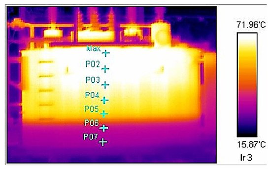
Figure 9. Transformer thermographic photograph [29].
Until now, various abnormal operating conditions that lead to transformer failure have been pointed out. However, it is not straightforward to enumerate them all. Table 1 summarizes, based on the information presented above and in [30][31], the failure modes and most recurrent causes that appear in each component.
Table 1. Failure modes and common causes are associated with the most important transformers’ components.
| Component | Failure Mode | Event | Cause |
|---|---|---|---|
| Core | Loss of efficiency | Blade displacement | —Eddy currents |
| Windings | Short-circuit | Mechanical damage | —Manufacturing deficiencies —Corrosion —Bad maintenance —Vibrations —Mechanical displacements |
| Insulation Failure | —Overvoltage —Overheating |
||
| Solid insulation | Cannot provide insulation | Mechanical damage | —Cellulose aging |
| Insulation Failure | —Cellulose Aging —Overheating |
||
| Insulation fluids | Short-circuit | Conductive particles in the oil | —Aging —Overheating |
| Overheating | Oil does not cool | —Pumps/Fans failure —Particles in oil (aging and overheating) |
|
| Bushings | Overheating | Partial discharges and loss of dielectric properties | —Insulator contamination —Water inlet —Aging |
| On-load voltage regulator | Inability to change the number of turns ratio | Mechanical damage | —Breakage of springs —Lack of maintenance —Old or burnt condensers —Carbonization —Switching system wear |
| Oil tank | Oil leakage | Damage to tank walls | —High gas pressure —Environmental wear |
| Cooling system | Overheating | Cooling incapacity | —Pipe cracks —Particles in oil (aging and overheating) —Pump/fan failures |
References
- Bohatyrewicz, P.; Mrozik, A. The Analysis of Power Transformer Population Working in Different Operating Conditions with the Use of Health Index. Energies 2021, 14, 5213.
- Walczak, K.; Gielniak, J. Temperature Distribution in the Insulation System of Condenser-Type HV Bushing—Its Effect on Dielectric Response in the Frequency Domain. Energies 2021, 14, 4016.
- Wang, D.; Zhou, L.; Yang, Z.; Liao, W.; Wang, L.; Guo, L. Simulation for transient moisture distribution and effects on the electric field in stable condition: 110 kV oil-immersed insulation paper bushing. IEEE Access 2019, 7, 162991–163002.
- Li, S.; Yang, L.; Li, S.; Zhu, Y.; Cui, H.; Yan, W.; Ge, Z.; Abu-Siada, A. Effect of AC-voltage harmonics on oil impregnated paper in transformer bushings. IEEE Trans. Dielectr. Electr. Insul. 2020, 27, 26–32.
- Liu, J.; Yang, S.; Zhang, Y.; Zheng, H.; Shi, Z.; Zhang, C. A modified X-model of the oil-impregnated bushing including non-uniform thermal aging of cellulose insulation. Cellulose 2020, 27, 4525–4538.
- Redmil, Presentation on the Slideshare Website. Available online: http://pt.slideshare.net/rezzmk/redmil-powerpoint (accessed on 20 December 2015).
- Ndiaye, I.; Betancourt Ramírez, E.; Avila Montes, J.; Jiang, Y.; Elasser, A. Grid Ready, Flexible Large Power Transformer; No. Final Technical Report: DE-OE0000852; GE Global Research: Niskayuna, NY, USA, 2019.
- Dohnal, D. On-Load Tap-Changers for Power Transformers; Maschinenfabrik Reinhausen GmbH Falkensteinstrasse: Regensburg, Gemany, 2013; Volume 8, p. 93059.
- Handley, B.; Redfern, M.; White, S. On load tap-changer conditioned based maintenance. IEE Proc.-Gener. Transm. Distrib. 2001, 148, 296–300.
- Al-Ameri, S.M.; Alawady, A.A.; Yousof MF, M.; Kamarudin, M.S.; Illias, H.A. The Effect of Tap Changer Coking and Pitting on Frequency Response Analysis Measurement of Transformer. In Proceedings of the 2021 IEEE International Conference on the Properties and Applications of Dielectric Materials (ICPADM), Johor Bahru, Malaysia, 12–14 July 2021.
- Xie, Q.; He, C.; Yang, Z.; Wen, J. Tests and analyses on failure mechanism of 1100 kV UHV transformer porcelain bushing. High Volt. Eng. 2017, 43, 3154–3162.
- Seo, J. Intelligent condition monitoring and diagnosis of a power transformer: On-load tap changer (OLTC) and main winding. Ph.D. Thesis, The University of Queensland, St Lucia, Australia, 2019.
- Brandtzæg, G. Health Indexing of Norwegian Power Transformers. Thesis in Engineering of Energy and Environment. Master’s Thesis, Norwegian University of Science and Technology, Trondheim, Norway, 2015.
- Saha, T.K.; Purkait, P. (Eds.) Transformer Ageing: Monitoring and Estimation Techniques; John Wiley & Sons: Hoboken, NJ, USA, 2017.
- Brodeur, S.; Lê Van, N.; Champliaud, H. A nonlinear finite-element analysis tool to prevent rupture of power transformer tank. Sustainability 2021, 13, 1048.
- Jahromi, A.; Piercy, R.; Cress, S.; Service, J.; Fan, W. An approach to power transformer asset management using health index. IEEE Electr. Insul. Mag. 2009, 25, 20–34.
- Wang, R.; Zhang, Y.; Jiao, B. Theory research on high performance control technology of large power transformer strong oil-cooled system. In Proceedings of the 2020 IEEE 4th Information Technology, Networking, Electronic and Automation Control Conference (ITNEC), Chongqing, China, 12–14 June 2020; Volume 1.
- Kim, Y.J.; Jeong, M.; Park, Y.G.; Ha, M.Y. A numerical study of the effect of a hybrid cooling system on the cooling performance of a large power transformer. Appl. Therm. Eng. 2018, 136, 275–286.
- Gao, X.; Schlosser, C.A.; Morgan, E.R. Potential impacts of climate warming and increased summer heat stress on the electric grid: A case study for a large power transformer (LPT) in the Northeast United States. Clim. Chang. 2018, 147, 107–118.
- Weiping, M.; Fangxiao, C.; Ying, S.; Chungui, X.; Ming, A. Fault diagnosis on power transformers using non-electric method. In Proceedings of the 2006 IEEE International Symposium on Industrial Electronics, Montreal, QC, Canada, 9–13 July 2006; Volume 3.
- Franzén, A.; Karlsson, S. Failure Modes and Effects Analysis of Transformers; Royal Institute of Technology, KTH School of Electrical Engineering: Stockholm, Sweden, 2007.
- Eyüboğlu, O.H.; Dindar, B.; Gül, Ö. Risk Assessment by Using Failure Modes and Effects Analysis (FMEA) Based on Power Transformer Aging for Maintenance and Replacement Decision. In Proceedings of the 2020 2nd Global Power, Energy and Communication Conference (GPECOM), Izmir, Turkey, 20–23 October 2020.
- Ciulavu, C.; Helerea, E. Power transformer incipient faults monitoring. Ann. Univ. Craiova–Electr. Eng. Ser. 2008, 32, 72–77.
- Bustamante, S.; Manana, M.; Arroyo, A.; Laso, A.; Martinez, R. Determination of Transformer Oil Contamination from the OLTC Gases in the Power Transformers of a Distribution System Operator. Appl. Sci. 2020, 10, 8897.
- Hussain, M.R.; Refaat, S.S.; Abu-Rub, H. Overview and Partial Discharge Analysis of Power Transformers: A Literature Review. IEEE Access 2021, 9, 64587–64605.
- IEC 60599:2015; Mineral Oi-Impregnated Electrical Equipment in Services-Guide to the Interpretation of Dissolved and Free Gases Analysis. Interna-tional Standard TC 10. IEC: Geneva, Switzerland, 2015.
- Qi, B.; Zhang, P.; Rong, Z.; Li, C. Differentiated warning rule of power transformer health status based on big data mining. Int. J. Electr. Power Energy Syst. 2020, 121, 106150.
- IEEE Standard C57.104-2008; IEEE Guide for the Interpretation of Gases Generated in Oil-Immersed Transformers. IEEE: Piscataway, NJ, USA, 2008.
- Cheng, L.; Yu, T. Dissolved Gas Analysis Principle-Based Intelligent Approaches to Fault Diagnosis and Decision Making for Large Oil-Immersed Power Transformers: A Survey. Energies 2018, 11, 913.
- Cheng, L.; Yu, T.; Wang, G.; Yang, B.; Zhou, L. Hot Spot Temperature and Grey Target Theory-Based Dynamic Modelling for Reliability Assessment of Transformer Oil-Paper Insulation Systems: A Practical Case Study. Energies 2018, 11, 249.
- de Faria, H., Jr.; SpirCosta, J.G.; Olivas, J.L.M. A review of monitoring methods for predictive maintenance of electric power transformers based on dissolved gas analysis. Renew. Sustain. Energy Rev. 2015, 46, 201–209.
More
Information
Subjects:
Engineering, Electrical & Electronic
Contributors
MDPI registered users' name will be linked to their SciProfiles pages. To register with us, please refer to https://encyclopedia.pub/register
:
View Times:
2.8K
Revisions:
2 times
(View History)
Update Date:
12 Jul 2022
Table of Contents


Notice
You are not a member of the advisory board for this topic. If you want to update advisory board member profile, please contact office@encyclopedia.pub.
OK
Confirm
Only members of the Encyclopedia advisory board for this topic are allowed to note entries. Would you like to become an advisory board member of the Encyclopedia?
Yes
No
${ textCharacter }/${ maxCharacter }
Submit
Cancel
Back
Comments
${ item }
|
${ item.createdUser.fullName }
${ item.createdAt }
${ item.vote }
${ item.reply }
Delete
${ reply.createdUser.fullName }
${ reply.createdAt }
${ reply.vote }
Delete
There is no reply to this comment~
${ item.replyTextCharacter }/${ item.replyMaxCharacter }
Submit
Cancel
More
No more~
There is no comment~
${ textCharacter }/${ maxCharacter }
Submit
Cancel
${ selectedItem.replyTextCharacter }/${ selectedItem.replyMaxCharacter }
Submit
Cancel
Confirm
Are you sure to Delete?
Yes
No