Electrospinning is a common method for fabricating drug-loaded fibers. The working fluid is gradually stretched into elongated solid fibers with the help of electrostatic force. Due to the influence of polymers, solvents, and other external conditions, the diameter of fibers usually varies from tens of nanometers to several micrometers. During this process, the drug is immobilized on the homogeneous fiber without destroying its own active molecular structure. Electrospun fibers have several advantages over other drug delivery systems. The high specific surface area of fibers facilitates drug dissolution. The desired drug dissolution process can be tailored according to the composition and structure of the fibers, thereby manipulating the controlled dissolution of the drug.
1. Coaxial Electrospinning
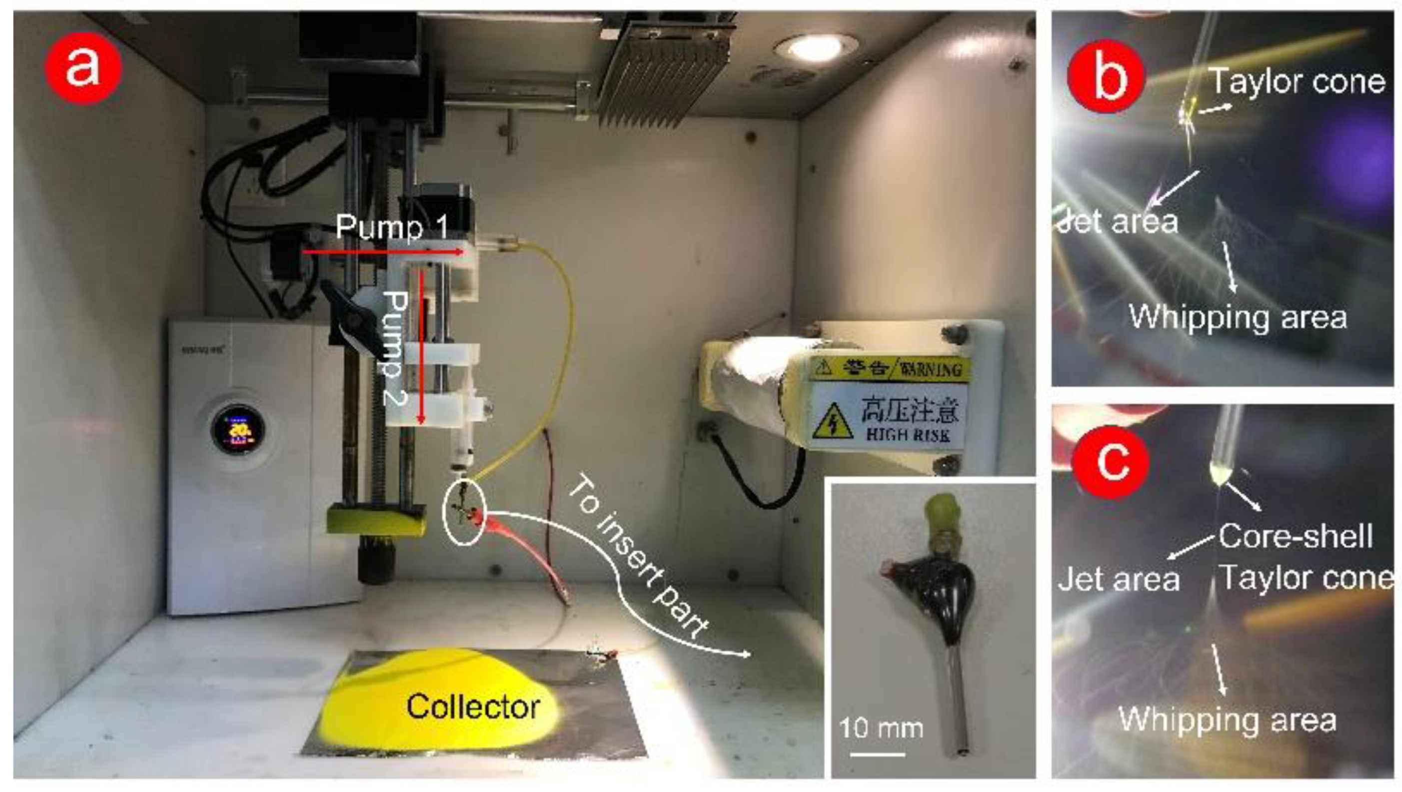
Traditional single and coaxial electrospinning can easily manufacture the working fluid from liquid to solid fiber under the effect of electrostatic fluid (Figure 1a exhibits). In this work, the homemade spinneret was a key component to fabricate double-layer or complex multilayer structures. The homemade spinneret (in the insert picture in Figure 1a), which consists of two metal capillaries (14 G and 17 G), was encapsulated, and fixed by epoxy resin.
Figure 1. Digital photos of the coaxial electrospinning process. (a) Instrument and environment for the preparation of coaxial electrospun F2 fibers, including humidity and temperature control system, pumps, silicone tube, collector, and spinneret. The insert picture shows an enlarged clear picture of homemade spinneret; (b) the process of fabricating F1 fibers; (c) the process of fabricating F2 fibers.
For a successful electrospinning process, the electrostatic repulsion between the same charge forces the droplets (from the working fluids) to form a Taylor cone. Subsequently, the solvent in the working fluid was quickly evaporated through stretching and thinning processes (unstable whipping area). Finally, the formed fibers were collected at a certain distance (usually 10–20 cm)
[1][2]. In
Figure 1b,c, the powerful dyeing effect of Cur causes a yellow Taylor cone at the spinneret. Compared with the clear yellow Taylor cone (
Figure 1b), a pale-yellow core–shell Taylor cone (
Figure 1c) could be attributed to the white PHBV working fluid in the outer layer. In traditional single-fluid electrospinning (preparation of F1 fibers,
Figure 1b), a gelatinous material appeared at the Taylor cone, which leads to the instability of the fiber fabrication process. The stable preparation process of F2 fibers (
Figure 1c) was due to the appearance of the semiarch-shaped Taylor cone.
2. Morphological Characterization of the Fiber Surface
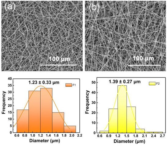
The SEM images of the two fabricated fibers in Figure 2a,b exhibited a linear cylindrical appearance. In Figure 2a, F1 fibers showed a curved and curled surface. This result could be predicted by combining with the digital picture of the electrospinning process in Figure 1b. In traditional single-fluid electrospinning, the gel substance appearing at the spinning nozzle caused interfacial surface tension and static electricity to fail to reach a dynamic equilibrium. Thus, the unexpected unstable electrospinning process caused fiber bending and curling. In Figure 2b, F2 fibers showed a straight fiber morphology with occasional beads, which could be attributed to the effect of PHBV working fluid in the outer layer. The electrospinning ability of pure PHBV solution to stretch into fibers is weak. Thus, the pure PHBV solution could not form fibers effectively. However, in this work, the addition component of PHBV (as a shell layer) optimizes the electrospinning process (Figure 1c) and increased the diameter of fibers (average diameters of F1 and F2 are 1.23 ± 0.33 and 1.39 ± 0.27 μm, respectively). The broken F2 fiber showed a clear core-shell structure, and the extra PHBV out layer led to an increased diameter.
Figure 2. SEM images of (a) F1 and (b) F2 fibers. The average fiber diameter is distributed directly below the corresponding SEM image.
3. Phase and Compatibility Analyses
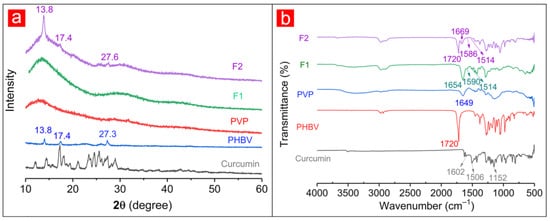
The XRD patterns of raw materials (i.e., Cur, PHBV, and PVP) and fibers were shown in
Figure 3a. A considerable number of Bragg diffraction peaks appearing in the XRD pattern of Cur suggested the crystalline properties of the Cur drug. Similarly, several diffraction peaks in the XRD pattern of PHBV could indicate the crystal structure of PHBV. Among them, the peaks at 13.8° and 17.4° indicated the α phase of PHBV and were attributed to the (020) and (110) crystal planes of PHB, respectively. Additionally, 2
θ = 27.3° was attributed to the (121) crystal planes of PHB
[3]. By contrast, the smooth XRD pattern suggested that PVP was amorphous. Although F1 fibers contained Cur, its XRD pattern had no sharp diffraction peaks like PVP. Similarly, apart from the three diffraction peaks of the known crystal PHBV in the F2 fibers’ XRD pattern, no other diffraction peak was related to Cur. During the electrospinning process, the crystalline drug was converted into an amorphous form. The drug-containing working fluid was stretched and solidified into fibers under the action of static electricity within several seconds at the spinning nozzle, and the drug was quickly fixed on the solid fiber during this period, thus losing its original crystal form
[4].
Figure 3. XRD patterns (a) and ATR-FTIR spectra (b) of raw materials (i.e., PVP, PHBV, and Cur) and fibers (i.e., F1 and F2).
The IR spectra of raw materials and drug-loaded fibers were obtained to explore the possible compatibility of components (
Figure 3b). The characteristic peaks at 3510, 1602, 1506, and 1152 cm
−1 of Cur demonstrate hydroxyl (-OH), carbonyl (-C=O), olefins (-C=C-), and ether (-C-O) groups, respectively
[5][6][7]. The characteristic -C=O groups of PHBV and PVP were observed in 1720 and 1649 cm
−1, respectively
[8][9]. For F1 fibers, the characteristic peak at 1654 cm
−1 represented the -C=O group of PVP, and those at 1590 and 1514 cm
−1 corresponded to the -C=O and -C=C- groups of Cur. Similarly, the characteristic peaks of PHBV (1720 cm
−1 for -C=O), PVP (1669 cm
−1 for -C=O), and Cur (1586 cm
−1 for -C=O, 1514 cm
−1 for -C=C-) appeared in the F2 fibers’ IR spectra. The characteristic peaks of Cur showed a deviation on F1 and F2 curves, suggesting that the formation of hydrogen bonds between the -OH group of Cur molecule and -C=O group of PVP molecule. The generation of hydrogen bonds promoted compatibility between Cur and polymer matrix, thus improving the stability of fibers.
4. Performance of Functional Fibers
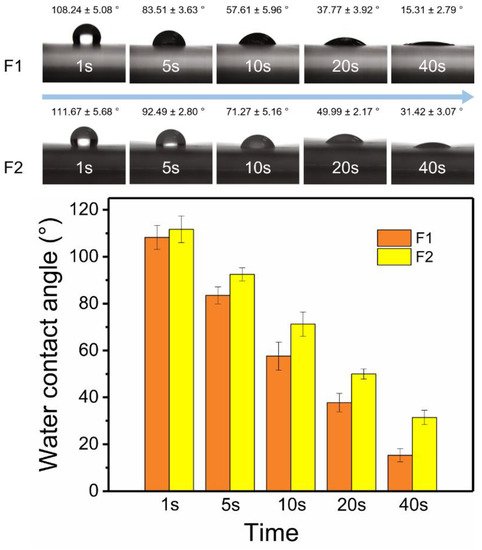
The surface hydrophilic properties of fibers were shown in Figure 4. In the first second, the water contact angle of F2 fibers (111.67° ± 5.68°) was slightly larger than that of F1 fibers (108.24° ± 5.08°). As time went by, the water contact angles of F1 and F2 fibers, which were 15.31° ± 2.79° and 31.42° ± 3.07°, respectively, gradually became smaller and stable at 40 s. The hydrophilic properties of two fibers were provided by PVP, and PHBV was responsible for the weaker hydrophilic properties of F2 fibers. The outer layer prevented the water molecules from entering the inner PVP layer, thereby delaying the intrusion of water molecules. More details could be observed on the digital pictures of the fibers after the water contact angle test. The aluminum foil and dissolved Cur were exposed due to the water droplets dissolve the PVP matrix of F1 fibers. By contrast, water had left a mark in the form of a core–sheath on the fiber mat (dark color in the inner layer and light color in the outer layer) in F2 fibers. This intuitive evidence suggested that the outer PHBV layer could inhibit water molecules from entering fibers.
Figure 4. Water contact angles of F1 and F2 fibers in 40 s.
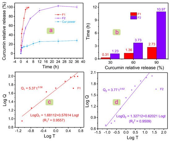
Figure 5a showed the drug dissolution profiles of Cur powder, F1 fibers, and F2 fibers. For poorly water-soluble Cur, it showed a burst release of 12.05 ± 3.66% in the first half hour, and only 28.26 ± 3.16% of poorly water-soluble Cur could be dissolved in 12 h. The lower solubility could be improved by the prepared two fibers. The F1 fiber could release 99.19 ± 2.24% Cur in only 4 h. PVP, a commonly used drug carrier, played an important role in the rapid release of poorly water-soluble drugs
[10][11][12]. However, the rapid deposition of local Cur (hard to absorb) affects the body. Thus, the sustained and stable release of Cur is needed. The coaxial electrospun fibers designed here could delay the release rate of Cur under the premise of ensuring the efficient release of Cur. F2 fibers released 100.14 ± 2.58% Cur in 36 h and had no initial burst stage. Drug molecules were stored in the core of fibers, and drug release was delayed due to the obstruction of the outer polymeric layer. Therefore, there was no initial burst release in F2 fibers. The combination of core–shell structure and raw polymeric materials (i.e., PHBV and PVP) not only improved the solubility of Cur, but also made it have a sustained-release drug profile of more than 24 h.
Figure 5. Drug dissolution results and analysis. (a) Relative release profiles of Cur powder, F1 fibers, and F2 fibers in 36 h. (b) Histogram of the relationship between Cur relative release and time in F1 and F2 fibers. Linear relationship between Log T and Log Q of (c) F1 and (d) F2 fibers, where Q is the relative release amount of Cur.
Figure 5b showed the relationship between the time required and the amount of Cur released at a certain stage was given. F2 fibers needed 1.23 h to release 30% Cur, whereas F1 fibers only needed 0.31 h. In the middle of the release of Cur (60%), F1 and F2 fibers needed 1.36 and 3.73 h, respectively. Subsequently, F1 fibers could release 90% Cur in 2.73 h, and F2 fibers needed 10.97 h. After the release of 90% Cur, F2 fibers needed a longer time (24 h) to release Cur completely compared with F1 fibers (4 h). Differentiated drug data showed the excellent performance of F2 fiber in the sustained release of the poorly water-soluble drug Cur.
Drugs in the two fibers could be released at a constant percentage rate, because of the higher correlation coefficient
R2 in the first-order kinetic model. The Higuchi model was used to describe the dissolution and diffusion behavior of drugs from the drug delivery systems. The higher
R2 indicated the two drug-loaded fibers had a diffusion release mechanism. The Rigter–Peppas equation was used to analyze the drug release kinetics deeply (
Figure 5c,d)
[13]. The equations for F1 and F2 fibers were
Q1 = 5.37
t0.58 (
R12 = 0.9557) and
Q2 = 3.77
t0.62 (
R22 = 0.9509), respectively.
n in
Q1 and
Q2 were 0.58 and 0.62, which were both in the range of 0.45–0.9. In general, it indicated that F1 and F2 fibers had both Fickian diffusion and skeleton erosion mechanisms. In fact, the drug was all stored in the PVP matrix inside the F1 and F2 fibers, and PVP was a water-soluble polymer; thus, F1 and F2 fibers should have a skeleton erosion mechanism. The difference between Peppas equations of F1 and F2 was not obvious, except for the slightly increased of
n value in F2 fibers. This suggested that the addition of the component PHBV layer had no adverse effect on the drug release kinetics in the fibers.
5. Mechanism of Drug Release in Fibers
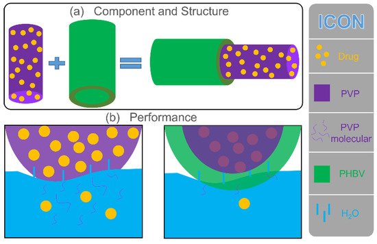
The drug release behavior was remarkably affected by the physicochemical properties of polymers. In this study, the PVP polymeric matrix, a common drug-loading carrier, had natural advantages for encapsulating some poorly water-soluble drugs. The rapid water solubility of PVP provided an effective solution for the release of poorly water-soluble drugs. The fabricated monolithic F1 fiber was composed of PVP, and the drug was evenly distributed on its surface and inside. As shown in Figure 6, water molecules penetrated F1 fibers from all directions to dissolve PVP quickly, and the drug active molecules diffused into the release medium due to the disappearance of the polymeric matrix. As an excellent drug carrier, PVP could load most of the drugs in the pharmacy field for rapid release. The prepared F2 fibers added a PHBV layer based on F1 fibers during the structure design. Therefore, the penetration of water molecules and the diffusion of drugs were more complicated than direct contact (F1 fibers). First, water molecules slowly penetrate the PHBV layer through diffusion and reached the inner PVP layer. Water molecules carried a small number of PVP molecules, and drug molecules returned to the release medium along the original path of diffusion. Finally, as the PHBV layer was completely penetrated by water molecules, a considerable number of PVP molecules and drug molecules slowly passed through the PHBV layer to the release medium along with the diffusion of water molecules. Compared with F1 fibers, core–shell F2 fibers remarkably increased the diffusion distance of the drugs from the storage space to the medium (Figure 6).
Figure 6. Mechanism of drug release in F1 and F2 fibers. (a) Component and structure of F1 and F2 fibers. (b) Schematic of the drug release of F1 and F2 fibers in water.
The design of the core–sheath structure and raw material PHBV changed the hydrophilicity of fibers (large water contact angle showed in Figure 4), which inhibited the diffusion of water to a certain extent and delayed the release of drugs (Figure 5), thus affecting the diffusion mechanism of drug molecules. The good improvement in material performance due to structure and raw materials had released a positive signal in the drug release system, providing a reference for future customized drug fibers.
 +1 credit