2.1. Viscosity
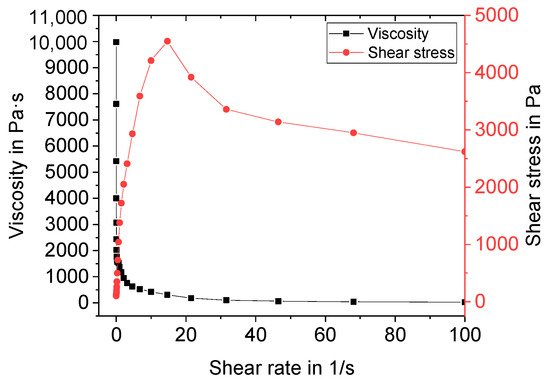
Manufactured suspensions were characterized regarding their rheological behavior before freeze foaming. A standard shear test with shear rates ranging from 0.01 to 100 s−1 was performed. An exemplary flow curve and the viscosity of Z5 (central point) are depicted in Figure 1.
Figure 1. Exemplary flow curve and viscosity of suspension Z5.
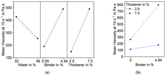
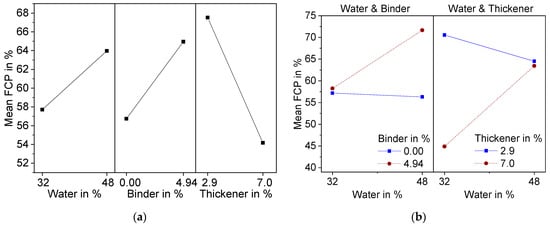
The suspension shows shear thinning behavior. Above a shear rate of 10 s−1, the shear stress suddenly decreases. This can be attributed to a lack of adhesion of the suspension to the plate. Therefore, slippage occurred at higher shear rates. For evaluation of the DoE, the viscosity at 10 s−1 was used. The results are presented in Figure 2 as a main effect plot (a) and interaction plot (b). The main effects plot shows the mean values of two different levels of the factors water, binder, and thickener contents. All three factors are, according to variance analysis in combination with backwards elimination, statistically significant (α < 0.1).
Figure 2. Effect plots of suspension viscosity at a shear rate of 10 s−1 resulting from DoE; (a) Main effects plot; (b) Interaction effect plot.
As anticipated, an increase in water content caused the viscosity of the suspension to decrease, whereas binder and thickener raised the viscosity. Additionally, binder and thickener showed significant interaction effects (
Figure 2b). At 2.9 wt.% thickener, there was only a small increase in viscosity due to the addition of binder, while the increase was significantly higher at 7.0 wt.% thickener. This can be attributed to the associative thickening effect between TAFIGEL AP15 and the PVA used as binder
[26].
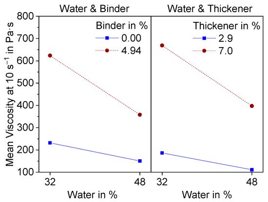
The interaction effects with water are shown in Figure 3.
Figure 3. Interaction effect diagram of water with binder and thickener on the Mean viscosity at a shear rate of 10 s−1.
Both effects have a level of significance greater than 0.1 (0.16, 0.15) and are therefore not statistically significant. Nevertheless, they both show the same interesting effect. At higher additive contents, the decrease in viscosity becomes more significant with increasing water content.
2.2. Macrostructure—Foam Cells
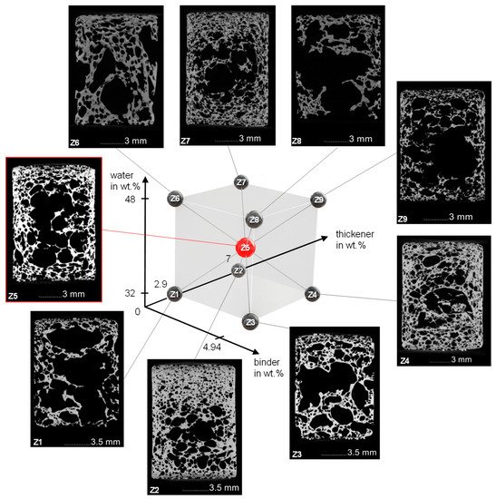
Sintered freeze foams were examined with CT-analysis. Cutting planes in the middle of the examined cylindrical foams including the structure of the DoE are presented in Figure 3. The corresponding foam cell porosity (FCP) is shown in Table 1.
Figure 3. Structure of the DoE with corresponding CT images of the sintered Freeze Foams.
Table 1. Foam cell porosity (FCP) of sintered Freeze Foams at the points of the DoE. For Z5 three foams were measured with a standard derivative of 0.9%.
| |
Z1 |
Z2 |
Z3 |
Z4 |
Z5 |
Z6 |
Z7 |
Z8 |
Z9 |
| FCP in % |
73.9 |
40.5 |
67.2 |
49.3 |
57.3 |
57.0 |
55.6 |
72.0 |
71.3 |
The FCP value ranges from 40.5% for Z2 (water and binder ↓, thickener ↑) to 72% for Z8 (water and binder ↑, thickener ↓). The cutting planes of the different foams show a large variety of foam cell morphologies. Common to all foams are the large foam cells in the middle as well as a densification at the lateral surface where the rubber mold hindered the expansion and at the primary surfaces where the sieves stopped further foam growth. Although the sieves should allow pore forming gases to escape when cell walls are torn, it seems this did not occur fast enough, so the resulting pressure increase inside the foam led to the growth of very large foam cells. It should also be mentioned that due to the limited resolution of 28.3 µm voxel size, very thin struts may not be visible in the CT scans. A more detailed examination of these different morphologies was not part of this study.
The statistically significant factorial effects after backwards elimination are presented in Figure 4 as a main effect plot (a) and interaction plot (b).
Figure 4. Effect plots of foam cell porosity (FCP) resulting from DoE; (a) Main effects plot; (b) Interaction effect plot.
Variation of thickener content showed the strongest effect in the form of a lowered FCP, which can be explained by the increase in viscosity due to the thickening mechanism of TAFIGEL AP15. Measurements of shear viscosity have proven this (Figure 2). Significant two-factor interactions were found for water–binder and water–thickener. For both, the porosity of the foam cells increases with increasing water content, but only at high binder or thickener contents. This can be explained by the more pronounced decrease of viscosity at higher additive content (Figure 3), although it must be stated that these findings are not statistically significant. Another possible explanation is the effect of polyvinyl alcohol to reduce the surface tension of water, thereby stabilizing air bubbles insight the suspension. That is why suspension with higher binder content might contain more air, which leads to larger foam growth. Moreover, a higher water content is associated with increasing amount of thickener (Equation (2)) so that viscosity becomes less dependent on the water content.
2.3. Microstructure—Strut pores
The strut porosity (StP) of sintered freeze foams was calculated according to Equation (3), based on the values listed in Table 2. The bulk density of sintered freeze foams is 3.1 g/cm3. StP values reach from 10.3% for Z2 to 36.5% for Z8. The results of the DoE are shown in Table 2.
Table 3. Foam weight mfoam, strut volume Vstrut and calculated strut porosity StP for sintered Freeze Foams at the different design points of the DoE.
| Design Point (Water-Binder-Thickener) |
mfoam in g |
Vstrut in cm3 |
StP in % |
| Z1 (32-0-2.9) |
1.2799 |
0.469 |
11.9 |
| Z2 (32-0-7) |
2.9308 |
1.054 |
10.3 |
| Z3 (32-4.94-2.9) |
1.5276 |
0.572 |
13.8 |
| Z4 (32-4,94-7) |
2.2250 |
0.847 |
15.3 |
| Z5 (40-2,47-4.94) |
1.6770 |
0.669 |
19.2 |
| Z6 (48-0-2.9) |
1.2117 |
0.596 |
34.5 |
| Z7 (48-0-7) |
1.5442 |
0.645 |
22.8 |
| Z8 (48-4.94-2.9) |
0.7752 |
0.394 |
36.5 |
| Z9 (48-4.94.-7) |
1.1027 |
0.435 |
18.2 |
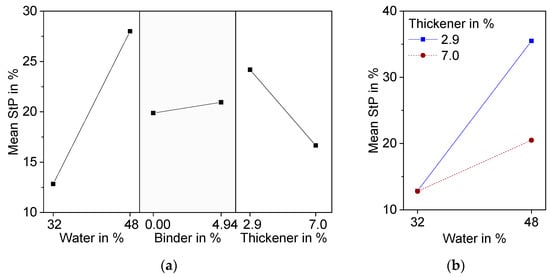
Significant factors are water and thickener and their interaction. Although the addition of binder leads to significant differences in pore morphology, especially at high water content, it is not significant with respect to strut porosity. Variance analysis resulted in a p-value of 0.53, which is above the chosen level of significance of 0.1. The hindrance of ice crystal growth is probably compensated for by an increase in pore volume due to burnout during thermal treatment. An increase in water content has the highest effect on StP, because water is a pore forming factor besides burned-out organic material. Higher amounts of thickener lead to a decrease in StP. It can be assumed that the increase in viscosity caused by thickener is responsible for this effect.
Water and thickener show significant interaction effects (Figure 4b). At low water content, increasing the amount of thickener resulted in very little decrease in StP, while the decrease in StP was much more pronounced at high water content. An explanation for this can be found in the cross-section images of the microstructure detailed in Figure 5. At 32 wt.% water, even at low binder and thickener contents, only small globular pores can be found (Z1). Therefore, in this case, an increase of thickener has no effect on freeze structure formation and thereby on strut porosity (Z2).
Figure 5. Effect plots of Strut Porosity (StP) determined with equation 3 resulting from DoE; (a) Main effects plot; (b) Interaction effect plot.
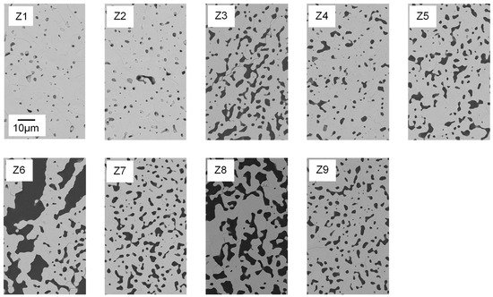
Figure 6. Polished cross-sections of Freeze Foams Z1–Z9, each at 1000× magnification recorded by electron microscopy (FESEM). The scale bar applies to all depicted cross-sectional images.
Strut pore morphology and pore size were characterized by means of FESEM and Mercury porosimetry. In Figure 6, FESEM images of foam struts from the nine different suspension compositions are displayed. Analogous to the foam cells, the struts also exhibited a large variety in pore morphology and size.
The shape of the pores ranges from globular (e.g., Z1, Z2) to interconnected channel pores (e.g., Z8), as displayed in
Figure 6. Only Z6 (water ↑, binder and thickener ↓) has a different strut pore morphology, exhibiting significantly larger pore sizes.
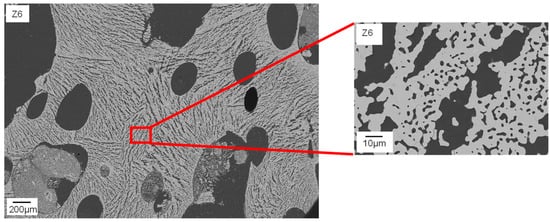
Figure 7 clarifies that the struts of Z6 show typical freeze structures commonly known from freeze casting
[16]. The combination of high water content and low viscosity seems to allow the growth of larger ice crystals during pressure reduction. Smaller globular pores between the lamellar pores (
Figure 7, right) can probably be referred to burned-out organic material.
Figure 7. FESEM image of the microstructure of a sintered Freeze Foam Z6. Struts show distinctive freeze structures.
In the struts of Z8, no lamellar pores are observed, although the suspension contained 48 wt.% water and displayed low viscosity. In contrast to Z6, it contained binder. Therefore, it can be concluded that binder molecules may have a large influence on ice crystal growth and thereby on strut pore morphology. This confirms the findings of Dedovets and Deville
[27]. Furthermore, in the struts of Z7 (water ↑, binder ↓, thickener ↑), no freeze structures are observed as well. In this case, the thickener content of the suspension was higher compared to Z6 (7 wt.%). Here, it is assumed that the increased viscosity of the suspension hinders the ice crystal growth and subsequently leads to smaller and more globular shaped, partly interconnected pores. Composition Z1 contains no binder and only 2.9 wt.% thickener, resulting in similar rheological properties to Z6. The only difference is the lower water content (32 wt.%). This leads to smaller particle–particle distances and therefore blocking of growing ice crystals, as stated by Naglieri et al.
[28] and recently confirmed by Schelm et al.
[29] and Dammler et al.
[30].
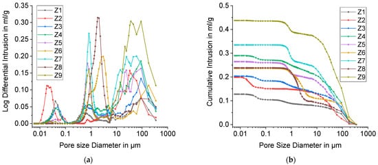
The results of Mercury porosimetry are shown in Figure 8.
Figure 8. Mercury porosimetry results for DoE points Z1 to Z9; (a) Log Differential Intrusion of mercury; (b) Cumulative Intrusion of mercury against the Pore size Diameter.
The pore size distributions display up to three peaks. The one at the far right reflects foam cells. Its range encompasses 5–400 µm with the exception of Z6, for which it starts at around 10 µm. These pore sizes can be attributed to the largest strut pores respectively. With Mercury porosimetry, only pores with a size smaller than 400 µm can be observed. For this reason, only a part of freeze foam porosity can be detected with this method and larger foam cells were analyzed separately with CT (
Section 3.2).
The middle peaks (2nd peak) in the pore size distribution starting at approximately 0.1 µm represent open strut pores. Table 3 shows the position of the 2nd peak. It has to be noted that with Mercury porosimetry only the size of pore openings is determined. For Z2, no distinctive 2nd peak was observed. Presumably, strut pores are mainly closed and not accessible for mercury. Moreover, the peak is much more pronounced for higher water contents (40, 48 wt.%), which means that there is a higher fraction of open and interconnected pores in the struts.
Table 3. Median size of strut pore openings determined by the position of the 2nd peak in the pore size distribution (Figure 8).
| Design Point (Water-Binder-Thickener) |
Pore Size 2nd Peak in µm |
| Z1 (32-0-2.9) |
0.5 |
| Z2 (32-0-7) |
- |
| Z3 (32-4.94-2.9) |
0.6 |
| Z4 (32-4.94-7) |
0.8 |
| Z5 (40-2.47-4.94) |
0.7 |
| Z6 (48-0-2.9) |
3.0 |
| Z7 (48-0-7) |
0.8 |
| Z8 (48-4.94-2.9) |
1.8 |
| Z9 (48-4.94.-7) |
0.8 |
The median pore size (2nd peak) reaches from 0.5 to 0.8 µm with the exception of Z6 (3.0 µm) and Z8 (1.8 µm). These values are in good accordance with FESEM images in Figure 7.
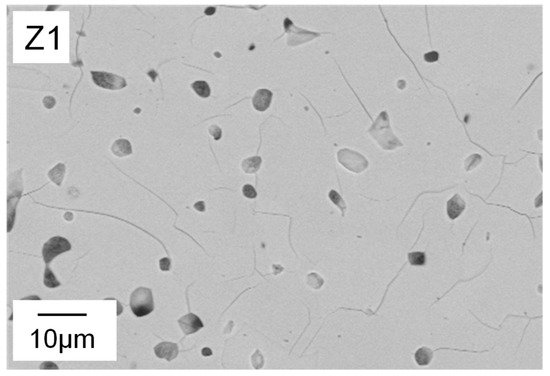
Interestingly, a third peak appeared between 0.01 and 0.1 µm, especially for foams with low water content. This is probably due to cracks that connect closed strut pores (Figure 9).
Figure 9. Polished cross-sections of Freeze Foam Z1 at 1000× magnification recorded by electron microscopy (FESEM) showing pores that are connected by cracks.
The area beneath the third peak represents the crack volume and the closed strut pore volume, which are detectable by Mercury porosimetry. Therefore, it can be concluded that closed StP is lowered with increasing water content, because only foams Z1–Z4 with 32 wt.% water exhibit a pronounced peak below 0.1 µm. As an alternative theory, the authors propose that there are open intergranular pores between the primary particles. At higher water contents, the ice crystals grow larger and force the HAp particles into denser packaging. This would result in smaller intergranular pores which disappear during sintering.
2.4. Model Suspension
In the sections above, the influence of the suspension parameters on the resulting freeze foam structure was investigated in detail. The following aim was to develop a composition that allows stable foaming with foam cell porosity (
FCP) around 60% by varying water content. With this model suspension, the influence of additional, important process parameters such as pressure reduction rate on the foaming behavior should be investigated. The following model equation resulting from the DoE was used to determine the optimal composition of the model suspension. The target factor is the
FCP:
A binder content of 1.3% was found to be well suited in combination with 4% thickener to guarantee stable foaming behavior and good demolding capability. Less binder would also be possible, but this leads to a reduced stability of the green foams. The predicted values for FCP for three different water contents are shown in Table 4.
Table 4. Predicted values for FCP . The value for binder was set to 1.3 and for thickener to 4.0.
| Water Content |
34 wt.% |
41 wt.% |
48 wt.% |
| Predicted FCP in % |
62.1 ± 2.0 |
60.8 ± 1.6 |
59.6 ± 2.4 |
In a water content span of 14 wt.%, the
FCP only differs by about 2.5%. The possibility to vary the water content while only slightly influencing the
FCP allows for adjusting the
StP, which influences for example the shrinkage during sintering. This allows to combine the high biocompatibility of the Freeze Foams
[21] with the constructional freedom of additive manufacturing approaches like lithography-based ceramic manufacturing (LCM) to create patient specific bone implants with improved compressive strength
[18]. Recently, Ahlhelm et al. used additively manufactured structures to be filled in green state with freeze foam and co-sintered both to a β-TCP hybrid structure that showed high biocompatibility
[31]. In the ongoing BMBF-funded project “Hybrid-Bone” (03VP07633), this hybrid shaping method is used to develop compressive strength-enhanced, biodegradable jaw-bone replacements.
Moreover, as stated above, a high strut porosity and even freeze structures in the struts are possible mainly at high water contents. These can be beneficial for bone replacement materials. That is why suspension with 48 wt.% water content was chosen for the following investigation of the foam growth.
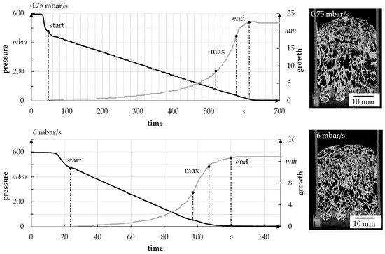
2.5. Results of Radiographical and CT Evaluation of the Foam Growth
To analyze the foam growth and structure formation via radiographic investigation, the model suspension with 1.3 wt.% binder, 4 wt.% thickener, and 48 wt.% water was used. It was foamed at different speeds and then scanned. The suspension was initially foamed with a pressure reduction rate of 6 mbar/s (quick) and 0.75 mbar/s (slow) to determine the limits, i.e., the start and end of foaming, of a foaming process (see Figure 10). In each case, six samples were used to perform the tests. For the used suspension, foaming starts at about 470–490 mbar and ends at 7–10 mbar, independent of the foaming rate. The fastest foam growth takes place in the range of 30–100 mbar.
Figure 10. Sample for growth of foam in relation to pressure reduction rate.
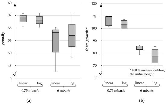
After analyzing the foaming process, the porosity and the foaming height of the foam were investigated. In each case, the pressure was reduced linearly as well as logarithmically since the freeze dryer ALPHA 2-4 LSC PLUS lowered the pressure logarithmically during the freeze foaming process. However, a linear pressure reduction allows a better analysis of the foam structure formation. In the following figures, both types of pressure reduction are compared with each other. A difference between linear or logarithmic pressure reduction could not be detected (median deviates less than 1% and can be ignored). Figure 11a shows that the porosity exhibits clear differences between fast and slow pressure reduction. The porosity is approximately 4–5% lower after a fast pressure reduction. Nevertheless, the foam volume is significantly higher under these conditions compared to the fast-pressure reduction scenario. Similarly, a significantly higher height of up to 20% can be observed with a slow pressure reduction (Figure 11b).
Figure 11. (a) Porosity; (b) Foam growth for 0.75 mbar/s und 6 mbar/s.
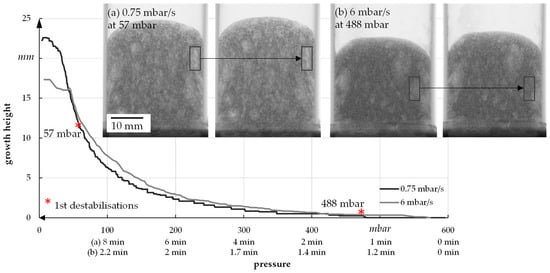
For a better understanding of the growth process, the foam growth is shown as a function of pressure for one sample (see Figure 12). In general, it has already been established that a slow reduction of the pressure leads to increased foam height as well as porosity.
Figure 12. Foam growth as a function of pressure.
The example radiographic images in Figure 12b show that at fast pressure (6 mbar/s) reduction, an exemplary foam cell (marked with a square) collapses at 488 mbar. This indicates the rupture of cell walls that leads to escaping air and water vapor and therefore inhibits further foam growth. For a slow pressure reduction, the first foam cells start collapsing at 57 mbar, which leads to a much higher foam growth but also larger foam cells (Figure 10). In general, the first destabilization effects appeared between 200 and 500 mbar at fast pressure reduction and between 30 and 70 mbar at slow pressure reduction. A slower pressure decrease also allows the system more time for water vapor production and attaining equilibrium conditions. The more water vapor, the higher the driving force for foam volume growth. However, at slow pressure decrease, the time until consolidation of the foam structure happens is longer compared to a fast decrease. That is why coalescence and Ostwald ripening are increased. Both effects lead to an inhomogeneous foam structure, which can be seen in Figure 15. To manufacture a homogeneous freeze foam with high foam cell porosity, it will be necessary to find an optimum pressure reduction rate that allows high foam growth but prevents destabilizing effects.
 +1 credit