 +1 credit
| Version | Summary | Created by | Modification | Content Size | Created at | Operation |
|---|---|---|---|---|---|---|
| 1 | Xinyu Fan | + 1537 word(s) | 1537 | 2021-12-29 10:39:55 | | | |
| 2 | Yvaine Wei | Meta information modification | 1537 | 2022-01-11 02:41:33 | | |
Video Upload Options
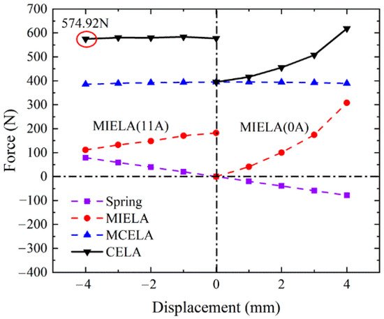
Electromagnetic linear actuators, as key executive components, have a vital impact on the performance of fully flexible variable valve trains. The research results show that the maximum starting force of the composited electromagnetic linear actuator (CELA) with the end-passive self-holding ability is 574.92 N while the holding force can approach 229.25 N. Moreover, the CELA is proven to have excellent dynamic characteristics and control precision under different motion modes and to have an improved adaptability to the complex working conditions of internal combustion engines.
1. Introduction
As the mainstream driving unit of valve trains, the moving iron electromagnetic linear actuator (MIELA) has the advantages of compact structure and high force density [1], but its single electric excitation type will lead to high energy consumption. The American company Engineering Matters, and Waindok, Yang and Professor Li Xinghu’s team proposed hybrid excitation schemes with better driving efficiency and considerable, end-passive self-holding capability [2][3][4][5][6]. However, the inherent nonlinear output driving force of MIELA limited the dynamic performance and control accuracy of the mechanism [7]. As with MIELA, the moving magnetic type was also based on the principle of minimum reluctance in the magnetic circuit. The German company Compact Dynamic [8] and Professor Mercorelli’s team [9] proposed a variable valve train scheme based on moving magnetic actuator. However, for the reason that its mover was a permanent magnet, the magnetic field changed obviously in the working process, which increased the difficulty of control.
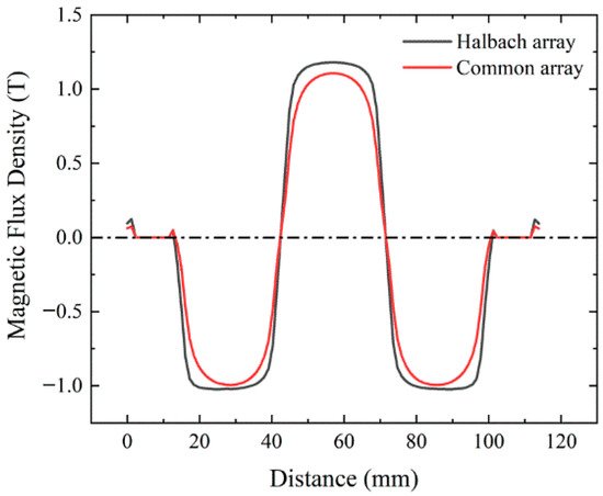
In recent years, the conventional moving coil electromagnetic linear actuator (MCELA) has attracted extensive attention. The working magnetic field of MCELA is generated by the permanent magnet, and the distribution does not change significantly. This kind of actuator has linear output force, fast response and good control performance. However, MCELA has a low force density, and its dynamic performance needs to be improved when facing high-pressure exhaust gas in the cylinder of internal combustion engines [10][11], and it also lacks end-passive self-holding capacity, which will lead to increased energy consumption.
2. System Structure Design
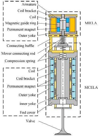
2.1. The MCELA
2.2. The MIELA
3. Three-Dimensional Finite Element Simulation
3.1. MCELA
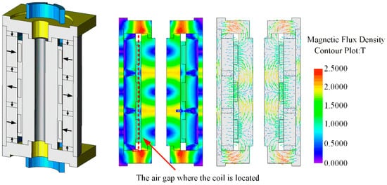
3.2. MIELA
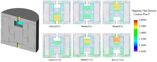
3.3. CELA
4. Conclusions
-
In CELA, MCELA (which has linear output force and good control performance) is the main driving part. As the auxiliary driving component, MIELA provides end-holding force and selective driving power.
-
A multi-mode motion coordination control strategy is established. When the load is large, the two driving parts are energized, and the starting force can be as high as 574.92 N. When the load is small, MCELA is energized alone, and MIELA moves with it to reduce the power consumption of the system.
-
At the end of the stroke, CELA has a passive holding force of 229.25 N, which means that additional current is no longer required to counter the disturbance of the gas load during the on/off phase of holding. Thus, it can effectively reduce energy consumption.
-
Under different motion modes, CELA can achieve continuous adjustable duration and maximum lift, and has good dynamic characteristics. At the same time, the steady-state error can be kept within ±0.02 mm, with high control accuracy.
References
- Tan, C.; Ge, W.; Fan, X.; Lu, J.; Li, B.; Sun, B. Bi-stable actuator measurement method based on voice coil motor. Sens. Actuators A Phys. 2019, 285, 59–66.
- Cope, D.; Wright, A.; Corcoran, C.J.; Pasch, K.; Fischer, D. Fully Flexible Electromagnetic Valve Actuator: Design, Modeling, and Measurements; SAE Intenational: Pittsburgh, PA, USA, 2008.
- Waindok, A.; Tomczuk, B.; Koteras, D. Modeling of Magnetic Field and Transients in a Novel Permanent Magnet Valve Actuator. Sensors 2020, 20, 2709.
- Yang, Y.-P.; Liu, J.-J.; Ye, D.-H.; Chen, Y.-R.; Lu, P.-H. Multiobjective Optimal Design and Soft Landing Control of an Electromagnetic Valve Actuator for a Camless Engine. IEEE/ASME Trans. Mechatron. 2012, 18, 963–972.
- Aslam, J.; Li, X.-H.; Janjua, F.K. Design of a hybrid magnetomotive force electromechanical valve actuator. Front. Inf. Technol. Electron. Eng. 2017, 18, 1635–1643.
- Tan, C.; Li, B.; Ge, W. Thermal quantitative analysis and design method of bi-stable permanent magnet actuators based on multiphysics methodology. IEEE Trans. Ind. Electron. 2019, 67, 7727–7735.
- Shao, D.; Sichuan, X.; Du, A. Research on a New Electromagnetic Valve Actuator Based on Voice Coil Motor for Automobile Engines; SAE MOBILUS: Pittsburgh, PA, USA, 2017.
- Hoffman, B. Fully Variable Valve actuation with electromagnetic Linear Motor. SIA Conf. Var. Valve Actuation 2006, 30, 1–8.
- Mercorelli, P. A Two-Stage Sliding-Mode High-Gain Observer to Reduce Uncertainties and Disturbances Effects for Sensorless Control in Automotive Applications. IEEE Trans. Ind. Electron. 2015, 62, 5929–5940.
- Schernus, C.; Van Der Staay, F.; Janssen, H.; Neumeister, J.; Vogt, B.; Donce, L.; Estlimbaum, I.; Nicole, E.; Maerky, C. Modeling of Exhaust Valve Opening in a Camless Engine; SAE International: Pittsburgh, PA, USA, 2002.
- Fan, X.; Yin, J.; Su, S.; Pang, H.; Song, Y. Loss analysis of electromagnetic valve train under different service conditions. Int. J. Appl. Electromagn. Mech. 2021, 66, 461–473.
- Li, Z.; Wu, Q.; Liu, B.; Gong, Z. Optimal Design of Magneto-Force-Thermal Parameters for Electromagnetic Actuators with Halbach Array. Actuators 2021, 10, 231.
- Liu, L.; Chang, S. Improvement of valve seating performance of engine’s electromagnetic valvetrain. Mechatronics 2011, 21, 1234–1238.
- Kim, J.; Joo, S.; Hahn, S.; Hong, J.; Kang, D.; Koo, D. Static Characteristics of Linear BLDC Motor Using Equivalent Magnetic Circuit and Finite Element Method. IEEE Trans. Magn. 2004, 40, 742–745.

