With the pandemic gripping the entire humanity and with uncertainty hovering like a black cloud over all our future sustainability and growth, it became almost apparent that though the development and advancement are at their peak, we are still not ready for the worst. New and better solutions need to be applied so that we will be capable of fighting these conditions. One such prospect is delivery, where everything has to be changed, and each parcel, which was passed people to people, department to department, has to be made contactless throughout with as little error as possible. Thus, the prospect of drone delivery and its importance came around with optimization of the existing system for making it useful in the prospects of delivery of important items like medicines, vaccines, etc. These modular AI-guided drones are faster, efficient, less expensive, and less power-consuming than the actual delivery.
1. Introduction
In today’s world, technology is getting increasingly more advanced and complex with every moment passing by. People are finding more ways to utilize energy in a more efficient way to obtain maximum output out of a machine, i.e., increasing efficiency to obtain the most use out of technology. Moreover, there is also the development of new technologies to boost the advancement and reduce human effort, minimize error, and bring about change for the betterment of society and mankind.
About 100 years back, when two brothers left the land and took the first step towards the sky, mankind has not looked back since then. Rather, they are striving further away from land towards the sky and universe. Since then, there have been multiple advancements and now the sky is within our grasp. Still, it is difficult for many in the world to access these wonders due to their large size, cost, etc. Now, these problems have also been fixed as they are cheaper and can fit in the palm of our hand and are available everywhere. Moreover, like every other technology, for the next step, they are now being used for daily aspects of our life. These small highly efficient systems are unmanned aerial vehicles (UAVs).
This paper is about increasing the efficiency so that they can perform better in that aspect of life. For example, recently, there is need for advancement in the delivery system, as the world is going through the COVID-19 pandemic, which is transmitted through human contact. There was a sudden need for contactless delivery and so drone trials were conducted for these deliveries, and now are being improved to completely take over human delivery. There is a major shortcoming in this area of research. While it is being advanced to follow the instructions to have a successful delivery, it is still running on a GPS and land tracking system. Now, these systems have the basic idea and outcome to give the minimum distance between two points, which is true in the case of travelling by land as all the constraints like mileage, performance, efficiency, etc. are in terms of distance and speed. For instance, during a journey by land, it is generally described through two points or by distance like Mumbai to Pune, but in aviation, the journey is by time like a 2-hour flight, so clearly, time is of greater priority.
On the other hand, UAVs are aerial vehicles where time is the measure of efficiency and output. A drone’s efficiency is calculated by how much flight time is given by it. Thus, GPS (used for coordinates or tracking) cannot be used as a path. The more efficient path is one using less time. Moreover, with the drone’s tech, distance and displacement mean the same thing. The upthrust and the forward speed work in sync to move the drone while the main challenge is to follow a certain path.
The primary challenges discussed in this paper are as follows:
-
First, the drone has to follow the path. For this, the path should be defined and also be a system that controls the motors and the body of the UAVs for the path to follow;
-
Secondly, the height limits. There are certain maximum heights for UAVs to fly at, which are decided by the legal bodies. It limits the area and also the path choices and the efficiency as there has to be a constant path where height would not increase though the UAVs still move forward;
-
The UAVs are automatic. The machine should be capable of making the decisions of when to start, ascend or descend, or just move straight;
-
As there are no guides or drivers, the machine should be self-driven. The air is full of traffic both natural and man-made, with buildings also soaring beyond imagination into the sky. The UAVs must be installed with an AI or guiding system to overcome barriers, precautions, and damage control, and also specific conditions as to when to activate what system. This must be overlooked by an AI, which is complex to develop;
-
As the UAV is automatic and its development will result in an increase, there must be some tracking systems that continuously transmit and store ion servers with all the changes during the journey until the journey is completed and during an emergency, it should be located easily.
2. Proposed Augmented Path-Time Architecture
In this paper, we found that there is a major flaw in UAV technology. Although the software is efficient, it is based on distance optimization techniques on which all the other land transportation is based. Rather, the UAVs or other aerial vehicles have time as a major factor for calculating their efficiency and output.
We used some great theories of physics and implemented them on aerial transportation to decrease the time and increase the output.
In modern chipsets like mamba f7 above, they have started to add and modify the flight controllers to the needs of the users. Not only do they have new features like Wi-Fi, Bluetooth, and GPS tracking device, but they also provide a whole set of different empty sockets and even storage and chips to modify, integrate, and even change the functioning of the flight controller to our needs. Although it is still in development, most modern flight controllers have this functionality, making it expensive and complex.
2.1. Blackbox
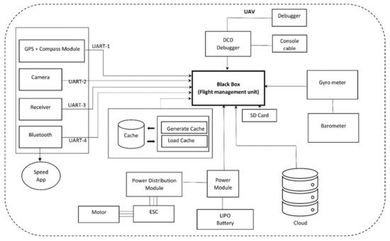
It contains 16 m flash memory and thus the processing and temporary storage of the algorithm. All the cache and real-time applications run in this part. It is the brain of the quad that carries out all the functionality of the algorithm and gives out the coordinates in real-time. It controls the quad and calls for the values to generate the required results to carry out the task.
2.2. Gyro Meter
It is the main component of the flight controller as it calculates the roll, yaw, and pitch and keeps the balance of the UAVs, and keeps it steady. Additionally, it has some onboard memory for storing and modifying purposes. The gyro meter keeps checking the angle of the inclination of the drone as well as the pitch and roll to prevent any failure and make sure the drone completes its task safely. It also feeds in the angle to Blackbox to track the path during the descent and ascent of the journey.
3.3. Curve of Ascent
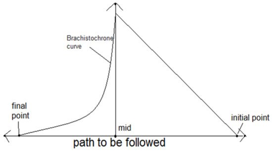
Although there can be many curves for the ascent, the most efficient in the case of timing is the inclined plane. The inclined plane at an angle of 45 degrees takes the least time and works to reach a point of height x meters and thus for the ascent, an inclined path to a certain height is calculated to minimize time. The inclined plane is the most efficient of all curves in the ascent, where all the forces of nature are bound to act against the drone. Therefore, an easy and efficient approach is easy to maneuver and maintain in the circumstance as the normal forces either cancel each other or some part of themselves in this curve, while all three coordinates depend on themselves to give more accurate and better coordinates for the drone to move.
The equation for the inclined plane should be (i.e., angle of inclination should be 45 degrees) for a perfect incline plane:
2.4. Curve of Descent
The Brachistochrone curve or curve of the fastest descent is used to reach the destination point. It is the most efficient curve in case of descent as it increases the efficiency and decreases the time of flight by a great margin.
The equation to be used in the algorithm is:
where a is the distance of the centre to an endpoint and θ is the angle between the path and the angle of the UAVs.
The brachistochrone curve is the fastest descent as with all the forces acting in favour of the drone and for this curve, only a small amount of adjustment and forces by the motors are required as all the others are provided by gravity and wind. The curve is free to move on the z-axis as the curve has specific angles and to accomplish it accurately, the drone has to have free movement along an axis to overcome any threat or damage in its way. The small step guarantees a higher gradient in altitude than any other curve, which makes it more prone to damage from things like buildings, animals, and stones so an axis free to move will prove to be an optimum solution.
2.5. Euclidean Distance
For the aerial transport to follow the path of ascent and descent accurately, the Euclidean distance is used. This function is used to calculate the distance between two different points. The two points (initial and final) denote the centre of the path detected. The two points are given coordinates assigned to them by the GPS module and then the Euclidean distance is calculated by a tracking algorithm that tracks the movement of the AV and calculates the coordinates and guides the vehicle to the path accurately and keeps checking if it is on track while simultaneously using the GPS module.
All these calculations are done simultaneously with the data being analyzed and used in real-time. These algorithms and calculations are carried out using different modules and chipsets on the flight controller of the UAVs. Figure 1 shows the final path followed by the UAVs as calculated by the algorithm.
Figure 1. Augmented path.
Now, in this path, we considered only the x and y-axis as in contradiction to the 3d world to keep it simple, but the z-axis is taken as being equal to x and y for the ascent as it has to keep a constant angle with the path (45 degrees).
The Euclidean distance interprets all the data in coordinates identifying every object with their coordinates and with its help, the drone will not only have decreased processing time but also by reading the coordinates of an incoming danger or a threat, the drone will also obtain help to identify the threat so it can work out the protocol to avoid it, thus helping in the task at hand and minimizing the chances of failure.
For the descent, the Brachistochrone curve is mainly for the x and y-axis so the z-axis could be kept constant.
2.6. GPS (Global Positioning System)
The GPS is used for the location of the initial and final destination of the journey and also the tracking of the UAVs. The drone has to be tracked through a remote computer and all the data is stored and manipulated by an AI; however, the tracking can be easily done through the GPS while also monitoring the progress and the path of the drone. Additionally, in case of failure, the GPS can be tracked to locate the drone for its retrieval. Figure 2 represents the architecture of the proposed augmented path-time model.
Figure 2. Proposed augmented path-time architecture.
3. Augmented Path Mapping Algorithm
Algorithm 1 is the first initializer of the program it sets of the system. It is the trigger, after which all the later algorithms follow. The Euclidean function is initialized. This function is used for calculating the set of values that defines the set of coordinates that the drone has to follow for keeping on the path. It also calculates the midpoint of the path. This midpoint is used for finding the point of descent at which the drone has to decrease its altitude to reach the ground at precisely the exact location.
To keep everything in check and track the values, a counter is set up with an initial value of zero. The counter values decide what is being calculated at the point being calculated.
| Algorithm 1 Algorithm to design the path |
Input: Initial and Destination Point
Output: Coordinates and Scale Of 3 Points Of Path
Initialization of variable: Assign zero to variable count, i
Initialize function Euclidean distance ()
Fetch parameters and store inside array a[], b[], Cal[]
dist. = ((a[i] − b[i]) × 2 + 550/((a[i + 1] + b[i + 1])/2) (a[i + 1] − b[i + 1]) × 0.5
Cal[i] = (a[i] + b[i])/2
Cal[i + 1] = (a[i + 1] + b[i + 1])/2)
Cal[i + 2] = (a[i + 2] + b[i + 2])/2)//mid-point coordinates x, y, z
Increase count to 1
Return(cal[]) |
Algorithm 2 is the ascent function that is used to define the path the quad has to follow while starting its ascent. The path is to be defined on all the axis, i.e., x, y, z-axis. There is also a mid-variable that keeps checking the coordinates and at precisely the midpoint the function ascent is ended, or the regulated height through the barometer readings to fly below the legally allowed height for the UAVs.
Now, there are two conditions if the midpoint or the height limit is reached first and that triggers either of the three or four functions, i.e., descent or the straight path.
| Algorithm 2 Algorithm for an ascent |
Input: Initial, destination, and cal point
Output: coordinates of ascent path
Initialize Function Ascent ()
Fetch parameters and store inside array a[], b[], Cal[]
Fetch manual real time readings from gyro meter for inclined angle
a variable with regulated permitted height
If(count == 1)//check the previous functions
Compute and store next set of coordinates using equation x = y = z
Check the coordinates with cal[]
If true increase the count by 1
Initialize function descent ()
Break//end the ascent
Else If height == barometer readings
Initialize function straight()
Break//start straight
Else continue |
If the mid-point is reached first, then Algorithm 3 or the descent function is initialized. The descent function is used to track the descent path using their respective equations. It has an end variable, which checks the final coordinates with the live coordinates and thus the progress is checked. All this is calculated in real-time and modified simultaneously during the flight of the quad (see Algorithm 3).
| Algorithm 3 Algorithm for a descent |
Input: Initial, destination, and cal point
Output: Coordinates of descent path
Initialize function ascent ()
Fetch parameters and store inside array a[],b[],Cal[]
Fetch automatic real time readings from gyrometer for inclined angle
If(count>=2)//check the ascent
x = a (〖θ − s in〗  〖θ)〗 〖θ)〗
y = a (1 − cos θ)//the next set of coordinates
If (x == b[0])||(y == b[1])//checking the end point
Break//end the function
Else continue |
If the height limit is reached first, Algorithm 4 is initialized. The straight function limits the drone movement from further change in the y-axis as the optimum height for the UAVs is reached and as it cannot go above, it moves in a straight line until the midpoint of the whole path is reached.
All the coordinates beside the mid-point are checked in real-time and values are called every instance from the sensors in place. The values are then calculated again for the path. This system is highly efficient as any changes or complications during the flight can be overcome by precautionary measures and then the path is again followed (see Algorithm 4).
| Algorithm 4 Algorithm for a straight path |
Initialize Function Straight ()
Fetch manual real time readings from gyro meter for inclined angle
If(count == 2)||(height == barometer readings)//only after ascent
Height remains constant
X = x + 1//only x changes following a straight path
If(coordinates == cal[])
Initialize function descent ()
Else continue |
Calling Technique of the Algorithm
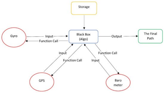
When the algorithm is compiled, it calls for values from the Blackbox via the function call, which already has the simultaneous values of the respective modules, i.e., gyro, barometer, etc., which is used in the flight controller for balancing and motor control of the quad. The Blackbox then provides the values of the respective functions in the algorithm, which gives the next set of coordinates for the drone to move on and this process goes on, thus giving the final path that the drone has to follow for the final destination.
The data is sent through the program at every single instance of time as the coordinates are generated throughout the journey for the progress and smooth running of the drone. All the data is processed for the next coordinates and each coordinate is checked to keep track of the ascent and descent.
Figure 3 is a small representation of the working of the algorithm from input to output.
Figure 3. The flow of data.
 +1 credit