Wireless power transfer systems (WPTSs) are considered as a promising technology to increase the acceptance of electric vehicles (EVs) . Compared to conductive charging, WPTSs offer vehicle charging without user intervention. This means that no cable handling and plugging are required. Thus, WPTSs provide a low-maintenance charging technology for EVs with high comfort and safety.
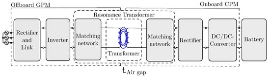
The working principle of WPTSs for electric vehicles is based on the electromagnetic interaction of an offboard ground pad module (GPM) and an onboard car pad module (CPM). The GPM typically comprises four main elements: a rectifier circuit, an inverter, a matching network and a transmitter coil. The CPM consists of a receiver coil, a matching network, a rectifier and, if necessary, a DC/DC converter.
1. Introduction
Wireless power transfer systems (WPTSs) are considered as a promising technology to increase the acceptance of electric vehicles (EVs)
[1][2]. Compared to conductive charging, WPTSs offer vehicle charging without user intervention. This means that no cable handling and plugging are required. Thus, WPTSs provide a low-maintenance charging technology for EVs with high comfort and safety.
The working principle of WPTSs for electric vehicles is based on the electromagnetic interaction of an offboard ground pad module (GPM) and an onboard car pad module (CPM). The GPM typically comprises four main elements: a rectifier circuit, an inverter, a matching network and a transmitter coil. The CPM consists of a receiver coil, a matching network, a rectifier and, if necessary, a DC/DC converter. The architecture of an exemplary WPTS is illustrated in Figure 1.
Figure 1. Overview of the necessary components of an exemplary wireless power transfer system.
This paper focuses on the onboard CPMs, which are usually mounted on the underside of EVs
[3]. This conceptional position results in high mechanical requirements due to underfloor impact scenarios
[3]. Therefore, conventional CPMs are robust and stiff constructions
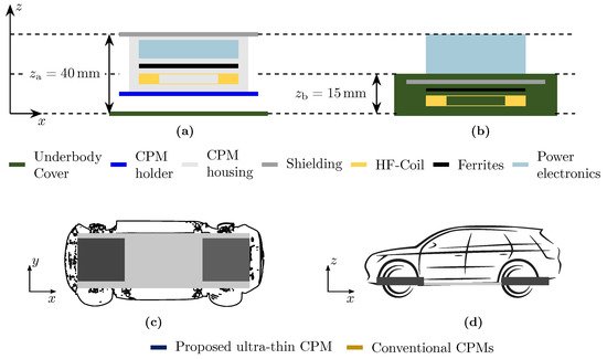
[3][4][5]. In detail, an underbody cover (UBC) typically encases the functional unit comprising a safety case, a CPM housing and a shielding to prevent interactions of the electromagnetic field with the surrounding components (see
Figure 2). However, this differential construction results in a relatively low volumetric and gravimetric power density combined with a high vertical dimension (z-dimension). This limits the possible installation position, which is often located in the front of the vehicle underbody due to the limited installation space. To enhance the interoperability of WPTSs and the possible installation space of CPMs, novel designs are required, which decrease the vertical dimensions of CPMs and increase the volumetric and gravimetric power density.
Figure 2. CPM designs—qualitative comparison of the z-dimension of: (
a) the conventional design of CPMs with a transmission power of 3.6 kW given in
[3], (
b) the proposed ultrathin CPM with a transmission power of 7.2 kW and the possible installation space of CPM designs in the (
c) xy-plane and (
d) xz-plane.
2. Proposed Wireless Power Transfer System
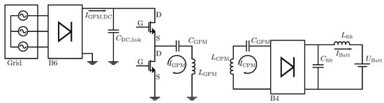
The setup of the utilized WPTS is shown in Figure 3. The GPM used a reduced and simplified implementation of the power electronics without power factor correction (PFC) as the test system was operating on an isolated grid. The AC/DC stage was a silicon B6-rectifier, which transforms the 3-phase input voltage into DC feeding a DC link capacitor CDC,link. As the power inverter, a SiC-MOSFET half-bridge module was utilized, which switches up to 100A RMS with up to a 100 kHz frequency. The serial–serial-compensated resonance transformer consisted of the inductors of GPM LGPM and CPM LCPM, as well as the offboard and onboard compensation capacities CGPM and CCPM of the matching networks. As the onboard rectifier, a SiC-B4 bridge was used, which converts the AC from the resonance transformer into DC feeding a DC link capacity Cfilt. An actively controlled or passive DC/DC conversion was not implemented per the design as the output voltage of the CPM resonant tank was above the battery voltage. The power control strategy was considered to be a mix between frequency-control and interleave mode operation. However, in the experimental setup, the power was controlled manually via the output voltage of the isolated power supply.
Figure 3. Setup of the utilized wireless power transfer system.
Table 1 summarizes the main system specifications and design constraints of the exemplary WPTS. According to SAE J2954
[6], the onboard coil area was restricted to an area of 300 mm × 300 mm. Interoperability was required within lateral misalignments of
x±75mm and
y±150mm and air gaps between 100 mm and 210 mm. The DC link voltage of the CPM was fixed to a high-voltage (HV) battery voltage. The DC link voltage of the GPM was adjustable between 0 V and 540 V.
Table 1. System specification and design constraints of the exemplary WPTS.
| Parameter |
Variable |
Value |
Unit |
| Output power |
Pout |
7.2 |
kW |
| GPM DC link voltage |
UGPM,DC |
0–540 |
V |
| CPM DC link voltage |
UCPM,DC |
300–470 |
V |
| Battery voltage |
UBatt |
300–470 |
V |
| Transmission distance |
s |
100–210 |
mm |
| Misalignment longitudinal |
△x |
±75 |
mm |
| Misalignment transversal |
△y |
±150 |
mm |
| Transmission frequency |
f0 |
81.38–90 |
kHz |
| Area of CPM coil (x,y) |
Acoil,max |
300 × 300 |
mm2 |
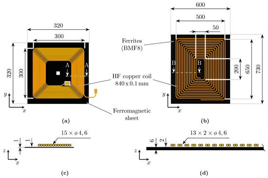
Based on the system specifications and the design constraints, the geometric and material specifications of the transformer components of the CPM and GPM were defined. Figure 4 shows the setup of the exemplary WPTS. The transformer parameters are summarized in Table 2.
Figure 4. Dimensions of the transformer components (unit: mm): (a) CPM, (b) GPM, (c) Section A-A and (d) Section B-B.
Table 2. Transformer parameters of the proposed WPTS.
| Parameter |
Variable |
Value |
Unit |
| Coil length |
lGPM |
500 |
mm |
| |
lCPM |
300 |
mm |
| Coil width |
wGPM |
650 |
mm |
| |
wCPM |
300 |
mm |
| Number of windings |
NGPM |
13 |
|
| |
NCPM |
15 |
|
| Self-inductance |
LGPM |
110 |
µH |
| |
LCPM |
112 |
µH |
| Mutual Inductance |
M |
7.6–24.3 |
µH |
| Magnetic Coupling |
k |
0.08–0.22 |
|
| AC resistance |
RAC,GPM |
<50 |
mΩ |
| |
RAC,CPM |
100 |
mΩ |
| RMS current |
IGPM |
20–50 |
A RMS |
| |
ICPM |
23–36 |
A RMS |
、
To maximize the given installation space while minimizing the z-dimension, the coil had a rectangular shape with 15 single-layer windings using a round stranded copper wire with
800×0.1mm. As an alternative to the commonly used ceramic ferrite plates, a flexible 320 mm × 320 mm ferromagnetic sheet was used, providing a flexible and highly permeable foil. It was assembled from multiple, alternately stacked layers of ferromagnetic film, as well as nonmagnetic, adhesive and protective coatings made from polyethylene terephthalate (PET), as given in
[7]. Overall, 30 layers were stacked to avoid saturation and high hysteresis losses, resulting in a total sheet thickness of 0.9 mm.
The lateral dimensions of the transmitting coil were 650 mm × 500 mm with a total number of 13 windings. The coil was underlaid with a layer of conventional BFM8 ferrite plates
[8], which offer low loss characteristics in the required frequency range. The same
800×0.1 mm stranded wire was used on the primary side, although each winding was laid in double to ensure current carrying capacity (see
Figure 4d).
 +1 credit