 +1 credit
| Version | Summary | Created by | Modification | Content Size | Created at | Operation |
|---|---|---|---|---|---|---|
| 1 | Massimiliano Pieraccini | + 1597 word(s) | 1597 | 2021-09-24 08:50:11 | | | |
| 2 | Jason Zhu | Meta information modification | 1597 | 2021-09-26 05:15:46 | | | | |
| 3 | Jason Zhu | -167 word(s) | 1430 | 2021-10-27 11:29:00 | | |
Video Upload Options
This is a fast MIMO-GBSAR (Multiple-Input Multiple-Output Ground-Based Synthetic Aperture Radar) operating in W-band (77 GHz). The radar can complete a scan in less than 8 s. Furthermore, as its overall dimension is smaller than 230 mm, it can be easily fixed to the head of a camera tripod, which makes its deployment in the field very easy, even by a single operator.
1. Introduction
Bridges require testing before going into service and need to be periodically monitored during their operative life for evaluating possible damage. Both testing and monitoring can be performed by static and dynamic measurements. The static test of a bridge is carried out by loading the deck with a dead load of several tons, and dynamic measurements are aimed at evaluating the response of the bridge stimulated by dynamic loads such as mechanical impulses, vibrodynes, and vehicular traffic.
Interferometric radars can perform both tests [1] operating in the real-aperture modality [2][3][4] or synthetic aperture modality [5][6]. The latter is usually called GB-SAR (Ground-Based Synthetic Aperture Radar).
Drawbacks of the current GB-SAR systems for structural monitoring are the slow acquisition rate (up to 90 s), physical dimensions (2–3 m) and weight (50–100 kg), which could preclude installation in many operative scenarios.
In order to reduce the acquisition time, MIMO (Multiple-Input Multiple-Output) systems have been proposed for bridge monitoring[7][8] and for environmental monitoring [9][10]. The MIMO radar reduces the acquisition time but dramatically increases hardware cost and complexity.
A way to reduce the size of a GB-SAR is operating at a higher frequency; for example, in W-band (77 GHz) instead of Ku-band (17 GHz). Radars operating in W-band have been proposed for different applications, especially in the automotive field[11][12][13][14]. These radars are characterized by small dimensions (often they are installed inside the headlight of a car) and by a fast repetition rate (up to 1500 Hz).
The first interferometric ArcSAR (circular synthetic aperture) operating in W-band was presented in 2018[15][16] by IDS Georadar, Pisa, Italy. This sensor, named HYDRA, operates at 77 GHz and performs a scan with a minimum time of 30 s. The sensor is able to co-register a radar image with a three-dimensional lidar scanner. The radar acquisition is projected on the 3D surface and the sensor can provide the displacement information of a 3D volume.
In this paper, the authors present a fast and small GB-SAR operating at 77 GHz based on a multiple MIMO radar. The MIMO antennas are positioned orthogonally with respect to the linear rail (or actuator) and the radar moves at constant speed along the guide. The azimuth resolution is provided by the movement along the linear rail, while the elevation resolution is provided by the MIMO architecture. The GB-SAR operates on-the-fly acquisition [20] for increasing the acquisition speed, reducing the blurring due to moving targets, and for increasing the duty cycle (the ratio between the total acquisition time and the repetition time during a measurement cycle). The radar is able to scan the scene in less than 8 s (which is the mechanic limit of the used actuator).
The main novelty of the proposed radar, with respect to the scientific literature (e.g., [16][15]) is the scan time of the order of a few seconds obtained by combining on-the-fly acquisition and MIMO architecture for elevation resolution. This feature opens many practical applications that are precluded by slower radar systems.
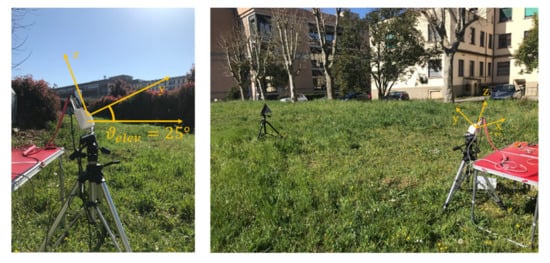
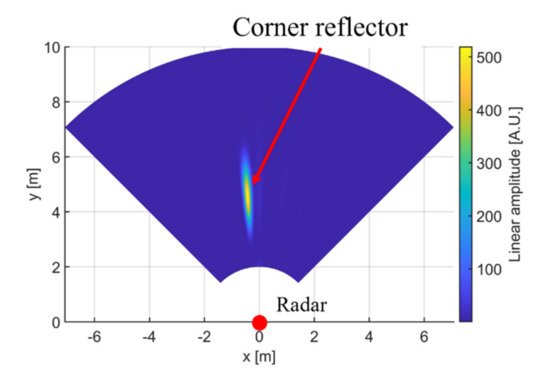
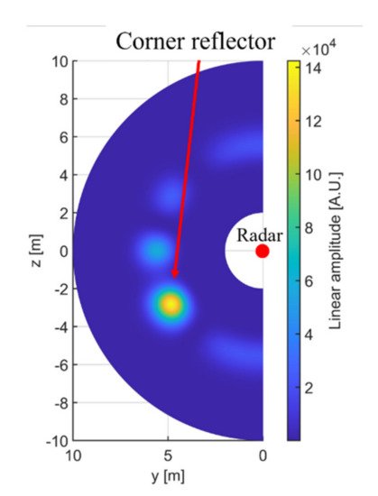
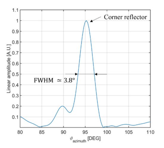
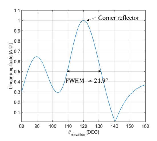
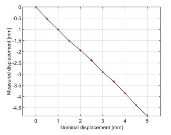
2. Controlled Scenario

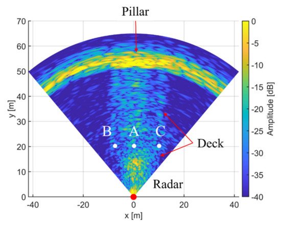
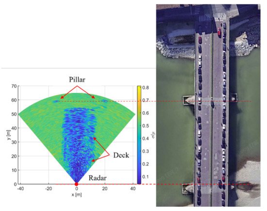
3. Vespucci Bridge, Florence, Italy
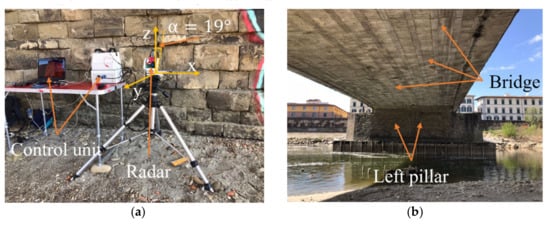
below the bridge and the left pillar was at about 52 m
4. Conclusions
References
- Pieraccini, M.; Miccinesi, L. Ground-Based Radar Interferometry: A Bibliographic Review. Remote Sens. 2019, 11, 1029. [Google Scholar] [CrossRef]
- Pieraccini, M. Monitoring of civil infrastructures by interferometric radar: A review. Sci. World J. 2013, 2013, 786961. [Google Scholar] [CrossRef] [PubMed]
- Luzi, G.; Crosetto, M.; Fernández, E. Radar interferometry for monitoring the vibration characteristics of buildings and civil structures: Recent case studies in Spain. Sensors 2017, 17, 669. [Google Scholar] [CrossRef] [PubMed]
- Shao, Z.; Zhang, X.; Li, Y.; Jiang, J. A comparative study on radar interferometry for vibrations monitoring on different types of bridges. IEEE Access 2018, 6, 29677–29684. [Google Scholar] [CrossRef]
- Dei, D.; Mecatti, D.; Pieraccini, M. Static testing of a bridge using an interferometric radar: The case study of ‘ponte degli alpini,’ Belluno, Italy. Sci. World J. 2013, 2013, 7. [Google Scholar] [CrossRef] [PubMed]
- Wang, Z.; Li, Z.; Mills, J. A new approach to selecting coherent pixels for ground-based SAR deformation monitoring. ISPRS J. Photogramm. Remote. Sens. 2018, 144, 412–422. [Google Scholar] [CrossRef]
- Pieraccini, M.; Miccinesi, L. An Interferometric MIMO Radar for Bridge Monitoring. IEEE Geosci. Remote. Sens. Lett. 2019, 16, 1383–1387. [Google Scholar] [CrossRef]
- Pieraccini, M.; Miccinesi, L.; Rojhani, N. Monitoring of Vespucci bridge in Florence, Italy using a fast real aperture radar and a MIMO radar. In Proceedings of the IEEE International Geoscience and Remote Sensing Symposium, Yokohama, Japan, 28 July–2 August 2019; pp. 1982–1985. [Google Scholar] [CrossRef]
- Tarchi, D.; Oliveri, F.; Sammartino, P.F. MIMO Radar and Ground-Based SAR Imaging Systems: Equivalent Approaches for Remote Sensing. IEEE Trans. Geosci. Remote. Sens. 2013, 51, 425–435. [Google Scholar] [CrossRef]
- Hu, C.; Wang, J.; Tian, W.; Zeng, T.; Wang, R. Design and Imaging of Ground-Based Multiple-Input Multiple-Output Synthetic Aperture Radar (MIMO SAR) with Non-Collinear Arrays. Sensors 2017, 17, 598. [Google Scholar] [CrossRef] [PubMed]
- Cong, X.; Liu, J.; Long, K.; Liu, Y.; Zhu, R.; Wan, Q. Millimeter-wave spotlight circular synthetic aperture radar (scsar) imaging for Foreign Object Debris on airport runway. In Proceedings of the 12th International Conference on Signal Processing (ICSP), Hangzhou, China, 19–23 October 2014; pp. 1968–1972. [Google Scholar]
- Steiner, M.; Grebner, T.; Waldschmidt, C. Millimeter-Wave SAR-Imaging With Radar Networks Based on Radar Self-Localization. IEEE Trans. Microw. Theory Tech. 2020, 68, 4652–4661. [Google Scholar] [CrossRef]
- Hasch, J.; Topak, E.; Schnabel, R.; Zwick, T.; Weigel, R.; Waldschmidt, C. Millimeter-Wave Technology for Automotive Radar Sensors in the 77 GHz Frequency Band. IEEE Trans. Microw. Theory Tech. 2012, 60, 845–860. [Google Scholar] [CrossRef]
- Feger, R.; Haderer, A.; Stelzer, A. Experimental verification of a 77-GHz synthetic aperture radar system for automotive applications. In Proceedings of the 2017 IEEE MTT-S International Conference on Microwaves for Intelligent Mobility (ICMIM); Institute of Electrical and Electronics Engineers (IEEE), Nagoya, Japan, 19–21 March 2017; pp. 111–114. [Google Scholar]
- Daria, D.; Amoroso, G.; Bicci, A.; Coppi, F.; Cecchetti, M.; Rossi, M.; Falcone, P. Advanced tomographic tool for HYDRA radar system. In Proceedings of the 12th European Conference on Synthetic Aperture Radar, Aachen, Germany, 4–7 June 2018; pp. 1–3. [Google Scholar]
- Cecchetti, M.; Rossi, M.; Coppi, F. Performance evaluation of a new MMW Arc SAR system for underground deformation monitoring. In Active and Passive Microwave Remote Sensing for Environmental Monitoring II; SPIE: Bellingham, WA, USA, 2018; Volume 10788, p. 1078801.

