Your browser does not fully support modern features. Please upgrade for a smoother experience.
Submitted Successfully!
 +1 credit
Thank you for your contribution! You can also upload a video entry or images related to this topic.
For video creation, please contact our Academic Video Service.
| Version | Summary | Created by | Modification | Content Size | Created at | Operation |
|---|---|---|---|---|---|---|
| 1 | Guorui Wang | + 5816 word(s) | 5816 | 2021-08-12 10:38:14 | | | |
| 2 | Lily Guo | Meta information modification | 5816 | 2021-09-06 05:59:24 | | | | |
| 3 | Lily Guo | Meta information modification | 5816 | 2021-09-06 06:00:44 | | | | |
| 4 | Lindsay Dong | Meta information modification | 5816 | 2021-10-09 11:39:39 | | |
Video Upload Options
We provide professional Academic Video Service to translate complex research into visually appealing presentations. Would you like to try it?
Cite
If you have any further questions, please contact Encyclopedia Editorial Office.
Wang, G. Hybrid Graphene/Fiber Reinforced Cementitious Composites. Encyclopedia. Available online: https://encyclopedia.pub/entry/13909 (accessed on 23 July 2026).
Wang G. Hybrid Graphene/Fiber Reinforced Cementitious Composites. Encyclopedia. Available at: https://encyclopedia.pub/entry/13909. Accessed July 23, 2026.
Wang, Guorui. "Hybrid Graphene/Fiber Reinforced Cementitious Composites" Encyclopedia, https://encyclopedia.pub/entry/13909 (accessed July 23, 2026).
Wang, G. (2021, September 06). Hybrid Graphene/Fiber Reinforced Cementitious Composites. In Encyclopedia. https://encyclopedia.pub/entry/13909
Wang, Guorui. "Hybrid Graphene/Fiber Reinforced Cementitious Composites." Encyclopedia. Web. 06 September, 2021.
Copy Citation
Graphene with fascinating properties has been deemed as an excellent reinforcement for cementitious composites, enabling construction materials to be smarter, stronger, and more durable. However, some challenges such as dispersion issues and high costs, hinder the direct incorporation of graphene-based reinforcement fillers into cementitious composites for industrial production. The combination of graphene with conventional fibers to reinforce cement hence appears as a more promising pathway especially towards the commercialization of graphene for cementitious materials.
This entry introduces the preparation and the enhancement of hybrid graphene-fiber reinforced cementitious composites.
graphene
graphene oxide
fiber
cementitious composites
1. Preparation of Hybrid Graphene-Fiber Reinforced Cementitious Composites
Direct mixing of graphene is the most straightforward and commonly used preparation method for the hybrid graphene-fiber reinforced cementitious composite. First, GO is typically synthesized from the oxidation of graphite followed by purification and exfoliation process. Ultrasonic preprocessing is required to ensure uniform dispersion of GO in water. To increase the dispersibility of GO, polycarboxylic-based superplasticizer or methyl cellulose is used as a primary dispersant dissolved in water [1][2]. Meanwhile, the fibers are mixed with cement, sand, and binder in a mortar mixer at low speed. Then, the sonicated GO dispersion can be added in the mixture and continuously stirred. The water/cement ratio of mixtures specimen is usually kept within the range of 0.2–0.5, as shown in Table 1. The mixtures are finally casted into steel molds and vibrated for densification after each casting. The surface of the castings is smoothed with a scraper and covered with preservative film to avoid water evaporation. Afterwards, specimens are demolded after 24 h initial hardening and then placed into a curing room (20 °C/RH 95%) until testing.
Table 1. Preparation and characterization of hybrid graphene-fiber fillers and reinforced cementitious composites.
| Material | Amount | Preparation | Characterization | Reference |
|---|---|---|---|---|
| GO/PVA fiber + OPC | -Volume fraction of 0.5% -GO/fiber mass ratio ≤ 0.15% -w/c~0.45 -s/c~1.5 -SP~0.2 wt.% |
Dip coating + mixing | SEM, FTIR, Raman, AFM | [1] |
| GO/CF + OPC | -Mass content of 0.1–0.4% -w/c~0.48 |
Electrophoretic deposition + mixing | SEM, FTIR, AFM | [2] |
| GO/CF + OPC | -Volume fraction of 1.0% -w/c~0.38 -s/c~1.0 -SP~0.047 wt.% |
Modified electrophoretic deposition + mixing | XPS, Raman, SEM, 3D Surface Metrology | [3] |
| rGO/PVA fiber + OPC | -Volume fraction of 2.0% -w/c~0.45 -s/c~1.0 -SP~0.2 wt.% |
Dip coating + mixing | XPS, Raman, SEM | [4] |
| GO/PE fiber + OPC | -Volume fraction of 2.0% -GO~0.008% wt.% -w/c~0.2 |
Dip coating + mixing | SEM, FTIR | [5] |
| GO + CF + OPC | -GO~0.04–1.0 wt.% -CF~1 wt.% -w/c~0.37 |
Direct mixing | SEM, TEM | [6] |
| GO/CF + OPC | -Mass content of 0.1–0.6% -w/c~0.44 |
Direct mixing | SEM, FTIR, XRD | [7] |
The most effective way to combine graphene and fibers is surface coating. Representative approaches for coating GO on micro-fibers involve dip coating, spray coating, chemical vapor deposition (CVD), electrophoretic deposition (EPD) method, sol-gel processing, and so forth [8][9]. For example, Yao et al. [1] employed a three-step dip coating method (Figure 1a) to fabricate the GO-coated polyvinyl alcohol (PVA) fibers. As illustrated in Figure 1b, polydopamine (PDA) was first covered onto PVA fibers through self-polymerization and subsequently grafted with polyethylenimine (PEI). The positively charged amine groups introduced by PEI help drive negatively charged GO flakes to the fiber surface via electrostatic attraction to build the amide bonds. Finally, the prepared PEI/PDA/PVA fibers were soaked into the GO solution (0.8 mg/mL) for 1 h to achieve a robust coating. Alternatively, Chen et al. [2] adopted the EPD technique to introduce GO coating on carbon fibers (CF). Before coating, electrochemical corrosion method was first used to remove the commercial sizing on the CF, in order to improve the interfacial adhesion. The electrolytic treatment system typically consists of a potentiostat/galvanostat analyzer with CF as the working electrode and a graphite cathode as the counter electrode, as shown in Figure 1c. Upon the immersion treatment of CF in GO solution (electrolytic solution, 1.5 mg/mL) for 40 min under the voltage of 15 V, the electrophoretic deposition was completed. Later, Lu et al. [3] developed a novel EPD system for the mass production of hybrid GO/CF fibers, as depicted in Figure 1d. Therein, a copper encapsulated plastic box was devised as the working electrode meanwhile containing a cluster of CF. Two holes were drilled on box and quantitative filter papers were then placed between the hole and copper paper, to allow the diffusion of GO electrolyte while avoiding the leakage of CF. Another copper plate was used as the counter electrode, kept 5 cm from the plastic container. The pH of the electrolytic solution was adjusted to 10.0 by adding sodium hydroxide into the GO solution. EPD process was finally conducted at 20 V for 1 h to coat GO on CF.
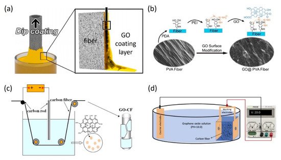
Figure 1. (a) Schematic representation of a typical dip-coating process [10] (Copyright permission Royal Society of Chemistry 2017); (b) Schematic illustration of the fabrication process of GO-coated PVA fibers [1] (Copyright permission Elsevier 2019); Schematic of (c) ordinary and (d) newly designed electrophoretic deposition system for the production of hybrid GO/CF fibers [2][3] (Copyright permission Elsevier 2015, 2018).
To confirm the successful coating and characterize the surface morphology and functional groups of GO on fibers, various characterization techniques are adopted including scanning electron microscopy (SEM) imaging, atomic force microscopy (AFM) imaging, X-ray photoelectron spectroscopy (XPS) analysis, Raman spectroscopy, and Fourier Transform Infrared Spectroscopy (FTIR) [1][2][4]. Figure 2a shows the typical SEM image of GO-coated PVA fibers, where a relatively smooth GO film with distributed wrinkles can be observed. In the magnified view, it is clear that GO flakes are folded and warped at the boundary. Based on AFM imaging, the thickness of GO coating can be measured by comparing the height difference between the uncoated fiber area and the flat coated area, giving a range of 50–500 nm. Due to the formation of wrinkles during the coating process, the surface roughness of hybrid GO/CF fiber appears higher than pristine CF (446 nm vs. 218 nm), as shown in Figure 2b. Such a roughening can induce a larger interfacial frictional resistance and benefit the load transfer within the cementitious composites. In addition, from the contact angle measurement (Figure 2c), GO coating endows CF with a higher wettability, displaying a contact angle of 98.4° compared to that of pristine one (149.9°). The hydrophilic surface feature will alleviate the dispersion issues and facilitate the cement hydration. Moreover, the Raman, FTIR, and XPS measurements all serve to identify the chemical composition and oxidized degree of GO coating present on fibers.
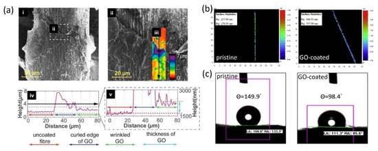
Figure 2. (a) Measurement of GO coating thickness on PVA fibers by AFM imaging of the boundary surface [1] (Copyright permission Elsevier 2019); (b) Surface roughness map and (c) contact angle measurement for pristine and GO-coated carbon fiber, respectively [3] (Copyright permission Elsevier 2018).
During the preparation of the cementitious composite, cement powder and sand are first dry mixed in a mortar mixer with a planetary rotating blade at low speed. Water is then added into the mixing batch until the desired flowability is achieved. Subsequently, graphene-coated fibers are added and dispersed in the cementitious mixture during the continuous mixing. Alternatively, fibers can also be dispersed in aqueous solutions prior to mixing with cement. In order to improve the dispersion of GO-coated fibers, GO solution can be used instead of the aqueous solution. Due to the ionization of the phenolic hydroxyl and carboxylic acid groups, electronegativity of the GO solution contributes to the better dispersion of GO-coated fibers in the GO solution. The larger electrostatic repulsion and steric stabilization between the GO result in the increased distance among the fibers [3].
2. Enhancement in Properties and Performance of Cementitious Composite by Hybrid Graphene-Fiber
2.1. Interfacial Properties
The reinforcing effect of cementitious composite is originated from the load-bearing capability of fillers, depending on the efficiency of load transfer from cement matrix. Therefore, the mechanical reinforcement of FRCC is not only dictated by the intrinsic mechanical properties of fibers but more importantly, the bonding strength at the fiber/cement interface. However, for certain fibers (e.g., carbon fiber) with inert and hydrophobic surface, they are prone to cluster in and interact with the cement matrix by weak van der Waals forces, thus considerably suppressing the mechanical reinforcement to cementitious composites. To this end, in addition to chemical functionalization, coating the fiber with GO affords another effective strategy to enhance the interfacial interactions between the fiber and cement matrix.
As mentioned in Section 3.3, abundant oxygen-containing functional groups can form strong chemical bonding as well as mechanical interlocking with C–S–H. This was directly evidenced by the SEM imaging of the fracture surface as shown in Figure 3a,b [3]. As a control group, pristine carbon fiber presents a smooth surface and an interfacial gap within the cement matrix, implying the occurrence of interfacial sliding due to the weak bonding. In contrast, a substantial amount of cement hydration products can be visible on the surface of GO-coated carbon fiber, which provide a higher interfacial bonding strength. Similar phenomena were also observed for other cementitious composites reinforced by, for example, rGO/CF, GO/PVA fiber, GO/polyethylene (PE) fiber [11][1][5]. Note that, compared with small GO flakes, large GO flakes are expected to achieve a full coverage of coating on fibers, hence performing better in acceleration of cement hydration and strengthening of interfacial bonds.
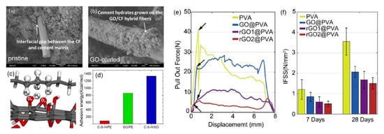
Figure 3. SEM image of fracture surface for (a) pristine and (b) GO-coated carbon fiber, respectively [3] (Copyright permission Elsevier 2018); (c) Typical pull-out force-displacement curves for the samples with 4 mm embedment after 28 days curing; (d) Interfacial shear strength of GO- and rGO-coated PVA fibers/cement composites cured for 7 and 28 days, respectively [4] (Copyright permission Elsevier 2020); (e) Pull-out simulation showing the hydrogen bonding resisting the relative sliding at the GO/PE interface; (f) Adhesion energy of interface in C–S–H/PE and C–S–H/GO/PE conditions [5] (Copyright permission Elsevier 2020).
To quantify the interfacial properties between GO/fiber and cement matrix, Lu et al. [5] carried out MD simulations to elucidate the contribution of GO to the interfacial behavior between PE fiber and cement mortar. As presented in Figure 3c, the hydrogen bonds are formed not only between GO and C–S–H, but also between GO and PE fiber. They are reversible and stable enough to resist the relative sliding of GO against the PE fiber. Quantitatively, the insertion of GO at the C–S–H/PE interface significantly improves the maximum pulling force by 42%, corresponding to the increase of interfacial friction from 1.16 MPa to 1.63 MPa. Meanwhile, the adhesion energy at the interface boundary, which offers the restoring force acting on PE chains, was also extracted as shown in Figure 3d. While the adhesion energy for C–S–H/PE interface is only 88 kcal/mol, it is enhanced to 862 and 1333 kcal/mol for GO/PE and C–S–H/GO interfaces, respectively. This suggests the critical role of GO filler in strengthening the interface connection between the PE fiber and C–S–H.
Theoretically, Li et al. [12][13] developed an analytical model to predict the tensile properties of the modified FRCCs, where the total stress of the composite (σc) is assigned to three contributions: the stress in the cement matrix (σa), the bridging stress (σf), and fiber prestress (σps). Specifically, the bridging stress is contributed by fiber reinforcement and governed by the interfacial property between the fiber and cement matrix. Based on the measurement of tensile strength of cementitious composite as well as the volume fraction and Young’s modulus of fiber and matrix, the chemical bond energy between the fiber and cement matrix can be determined. Based on this model, Yao et al. [1] found that chemical bond energy for GO-coated PVA fiber/cement reached 217.8 J/m2, almost 80 times that of pristine PVA fiber/cement with a chemical bond energy of 2.7 J/m2.
Yao et al. [4] performed single fiber pull-out test for GO-modified PVA fiber embedded in Ordinary Portland cement (OPC). By recording the maximum pull-out force (Figure 3e), the interfacial shear strength (IFSS) can be obtained based on known fiber diameter and embedded length [14][15]. Interestingly, as shown in Figure 3f, the IFSS for GO- and rGO-coated fiber/cement samples cured for 7 days exhibit even lower values than pristine fiber/cement systems. Similar IFSS trends can also be found in samples cured for 28 days (Figure 3f). One possible reason is that the stacks of multiple GO flakes are subjected to an interlayer slip under the shear loading in pull-out test. It has been reported that the interlayer shear strength between GO and rGO layers are relatively weak, while the topological defects would further cause a drastic reduction in interlayer shear strength [16][17]. Hence, while GO layers can form strong hydrogen bonds with both PVA and C–S–H, they might suffer from the cohesive failure prior to the adhesive failure, leading to the low IFSS.
The incorporation of GO coating not only affects the interfacial load transfer, but also regulates the microstructures and mechanical properties of cement in the interfacial transition zone (ITZ). In this regard, a low-melting-point intrusion method was exploited to characterize the ITZ structures surrounding the GO/PVA fiber. Backscattered electrons (BSE) image of the cross-sections of the ITZ is given in Figure 4a, showing the spatial distribution of the pore diameter (dp). In the case of pristine fibers, a number of large pores with dp > 40 mm are visible in the ITZ. The porosity tends to decrease with increasing distance from the fiber surface and gradually approaches the level of the bulk cement. Quantitatively, the percentage of small pores is (0.1 mm < dp < 1 mm) is summarized as ~25% as shown in Figure 4b. By contrast, the sample with GO coating manifests an enhanced percentage of ~35% for small pores but a significant reduction in large pores. Consequently, the overall porosity is found to be greatly declined as seen in the inset, indicating of a densification effect of GO. However, due to the removal of oxygen-containing functional groups by reduction, an opposite trend is observed for rGO samples.
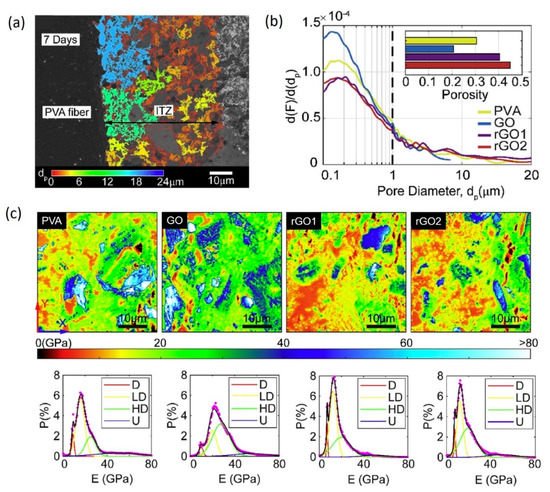
Figure 4. (a) BSE images of ITZ of PVA fiber/cement samples cured for 7 days, showing a color map of the equivalent pore diameters (dp); (b) Pore size distribution for various composite samples cured for 7 days. Inset shows the overall porosity of corresponding ITZs; (c) PeakForce QNM contour maps of the elastic modulus of the ITZ between cement and fibers and corresponding probability distribution of different phases in QNM contour maps, including holes and defects (D), low-density hydration product (LD), high-density product (HD) and unhydrated grains (U) [4] (Copyright permission Elsevier 2020).
Furthermore, the elastic properties of the ITZ were evaluated by AFM-based PeakForce Quantitative Nanomechanical Mapping (QNM) [18]. To ensure the flatness requirement for the sample, low-modulus hardened epoxy was filled into the cracks and holes. Contour maps of the elastic moduli (E) of the ITZs for different systems are presented in Figure 4c, wherein different phase domains can be identified, including defects (E < 12 GPa), low-density (13 < E < 26 GPa) and high-density (26 < E < 39 GPa) C–S–H as well as unhydrated grains (E > 39 GPa) [19]. Remarkably, the addition of GO coating results in a decrease of the percentage of defects from 16.4% to 5.3%, while the percentage of C–S–H, including both low-density and high-density, increases from 70.22% to 73.8% in the ITZ. This coincides well with the filling effect as discussed in Section 3.2. On the contrary, the reduction of GO appears to increase the percentage of holes and reduce the percentage of C–S–H in ITZ.
We can conclude that enhancement of interfacial properties between GO-coated fibers and cement can be ascribed to more efficient load transfer at the fiber/cement interface due to increased interfacial shear strength and adhesion resulting from the formation of chemical bonding as well as increased friction on the fiber surface. This implies that the control of functionalization and thickness of graphene flakes may serves as a tuning strategy to achieve optimized interfacial properties [20][21].
2.2. Mechanical Properties
Extensive studies have reported the incorporation of graphene as reinforcing fillers accounts for substantial enhancement of mechanical properties of cement materials [22][23][24]. The mechanical reinforcing mechanisms are mainly ascribed to the nucleation effect, filling effect, interfacial bonding effect, and toughening effect, as summarized in Section 3. The performance of cement-based materials is commonly evaluated from mechanical properties that include elastic modulus, tensile strength, compressive strength, and flexural strength, among which compressive and flexural strength are deemed as an indexing property and serve as the evaluation criteria for whether the cement can satisfy the engineering requirements.
One representative example is GO-coated CF reinforced cement paste which shows improvements in both flexural and compressive strength (Figure 5a,b) [2]. Specifically, GO-CF (0.4 wt.%)/cement cured for 28 days exhibits the highest flexural strength of ~7 MPa and compressive strength of ~30 MPa, yet the mechanical enhancement appears inconspicuous. Similar strengthening phenomena in GO-CF (1.0 wt.%)/cement composites were also reported by Lu et al. [3], who performed GO coating with a newly designed EPD method. Figure 5c shows experimental results of compressive strength and flexural strength of cement paste reinforced by the CF and GO/CF fibers. Here, GO/CF-cement corresponds to the GO/CF in aqueous solution while GO/CF-GO-cement samples are obtained by dispersing GO/CF fibers first in GO solution and then mixed with cement powders, to achieve a better dispersion due to stronger electrostatic repulsion and steric stabilization. Compared with the control groups, GO/CF fibers bring a much higher compressive and flexural strength to the cement paste. The reasons can be attributed to the abovementioned reinforcing mechanisms as well as the extraordinary mechanical properties of GO itself. In addition, a better dispersion of GO/CF fibers in GO solutions further enhances the mechanical performance of cement paste. Obviously, the highest compressive and flexural strength are achieved by GO/CF-GO-cement, as high as 40.3 MPa and 18.2 MPa respectively. This results in 14.8% and 8.7% increase respectively in contrast to the control cement paste, showing a compressive strength of 29.8 MPa and flexural strength of 11.1 MPa. By directly mixing GO solution (0.06 wt.%) with CF (1.0 wt.%)/cement, Chen et al. [6] reported a 23.9% increase in compressive strength and more than 100% increment in flexural strength. It was found that the compressive strength is only affected by the presence of GO, whereas CF play a joint role in flexural strength. With increasing GO content from 0.06% to 1.0%, the mechanical enhancement of compressive and flexural strength can be further elevated to 46.9% and 43.6%, respectively.
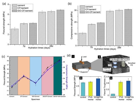
Figure 5. (a) Flexural and (b) compressive strength of the cement paste (with 0.4 wt.% CF/GO-CF) at 7 days and 28 days [2] (Copyright permission Elsevier 2015); (c) Flexural and compressive strength of GO/CF/cement specimens [3]; (d) Measurement of flexural strength and toughness of GO/PVA/cement by a three-point bending test [4] (Copyright permission Elsevier 2020).
Comparatively, different enhancements in mechanical properties of GO-CF/cement composites are reported. Potential reasons can be attributed to the differences in sizes, filler content, and functionalized degree of GO, as well as the degree of dispersion. As expected, larger surface area can benefit the nucleation effect and interfacial bonding effect, and good dispersion is favorable of the toughening effect and filling effect. Likewise, a higher concentration of graphene in the cement matrix can also bring forth a pore filling effect, more compact and refined structures in cement composites, leading to a better mechanical performance.
Yao et al. [4] carried out three-point bending tests to explore the effect of GO on the mechanical performance of PVA fiber-reinforced cementitious composites, as shown in Figure 5b. The incorporation of pristine PVA fibers in cement mortar can mildly increase its flexural strength by only ~5%. In contrast, GO coating on PVA fibers makes the flexural strength dramatically increase up to 4.49 MPa for GO@PVA mortar. A more significant reinforcing effect is found in flexural toughness, which is calculated based on the area under load-deflection curves. As shown in Figure 5d(iv), the flexural toughness is growing from ~0.1 J for plain cement mortar to 0.64 J for PVA mortar, and finally reaches 0.704 J for GO@PVA mortar. Such a ductile behavior came from the relatively weak interfaces between fiber and cement which is associated to the energy dissipation mechanism.
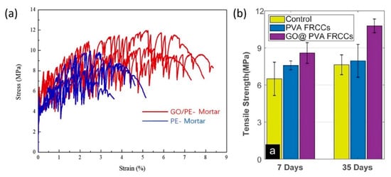
Tensile strength of FRCC is one of the major parameters to measure mechanical properties. Uniaxial tensile test is a common way to measure the tensile properties of cementitious composites. Figure 6a displays typical stress-strain curves of cement mortar reinforced by PE and GO/PE fibers in uniaxial tensile tests. Multiple drops can be visible which suggest a series of cracking during the deformation, due to the porous nature of cement mortar. It is clear that the first cracking strength of GO/PE-Mortar is around 4.9 MPa, almost 12% higher than that of PE-Mortar (4.4 MPa). In addition, the tensile strength (maximum tensile stress) can reach 10.4 MPa, which is 46.3% improvement compared to the PE-Mortar (7.1 MPa). The most salient feature is the ultimate tensile strain, showing a 70.4% enhancement from 3.75% (PE-Mortar) to 6.39% (GO/PE-Mortar). Such strain-hardening properties of mortar are attributed to the densified microstructures and improved bonding at ITZ [5]. Yao et al. [1] also studied the splitting tensile strength of the GO/PVA fiber-reinforced cementitious composites. As shown in Figure 6b, the introduction of pristine PVA fibers can increase the tensile strength of the 7-day and 35-day samples by 16.8% and 4.1%, respectively, compared with the plain cements. With the GO modification, the splitting tensile strength of the 7-day samples further improves by 32.2% compared to the control group and such an enhancement rises to 41.2% after 35-days curing. Furthermore, based on the tensile stress-strain curves and starting from the theoretical model proposed by Li et al. [12][13] as discussed in Section 4.1, Yao et al. [4] estimated the tensile strength of PVA fiber/cement composites to be 6.18 MPa, which was increased to 7.83 MPa after introducing the GO coating. Meanwhile, an enhancement of toughness was deduced, from 2.94 to 33.16 kJ/m. Conclusively, the GO modification of PVA fibers can simultaneously improve the mechanical strength and toughness for FRCC.
It can be concluded that the intensified mechanical reinforcing effect can be associated with four aspects: (1) The ultrahigh stiffness and strength of graphene itself; (2) Strengthening of the fiber interface properties that allows a higher load carrying capability of fibers in the composite; (3) Stiffening of cement matrix within the ITZ by densification of microstructures; (4) Toughening mechanism provided by graphene and fibers. In this respect, it can be envisioned that moderate reduction of GO would benefit the mechanical enhancement, as it restores the hexagonal structures of pristine graphene by eliminating defects while maintaining adequate surface functional groups to keep strong bonding with cement matrix. Besides, the modifying effect of ITZ to cementitious composites is anticipated to be enhanced with increasing graphene content if the dispersion issue can be well addressed.
Such design principles can also be extended to other building materials, such as geopolymers. Geopolymer composites are the most promising environmentally friendly alternative to traditional cement materials (e.g., Portland cement) [25]. Given the high quasi-brittle behavior of geopolymers (due to their ceramic-like characteristics), fibers and graphene-based materials have been used as reinforcements to produce stronger and tougher composites, showing tremendous potential in a broad spectrum of applications including supercapacitors, fire-resistant coating, and so forth [26][27][28][29]. It can be envisaged that the hybrid graphene-fiber reinforcements will further improve the mechanical and durability performance of geopolymer composites, and endow them with functionality and versality.
2.3. Durability Performance
The durability performance of cement-based materials has long been a major concern in the construction industry especially considering their susceptibility and vulnerability to aggressive environments. From the structural point-of-view, the durability of cementitious composites is primarily affected by the porosity characteristics, which play as a dominant role for both mechanical and chemical durability performance [30]. It has been documented that pores having sizes larger than 20 nm would act as channels within the cement, through which water molecules and aggressive chemical species diffuse [31]. In this respective, the addition of graphene fillers can increase the resistance to permeability and relevant corrosion, thus improving the durability performance of FRCC.
In order to investigate the impermeability of cementitious composites, Jiang et al. conducted rapid chloride migration tests and measured chloride migration coefficient (DCl), which is one of the important indexes to characterize the resistance to chloride ion permeation of cement-based materials. As shown in Figure 7a, adding either PVA fibers or GO alone can effectively reduce the DCl, yet GO shows a higher efficiency with a decreasing magnitude of 35.6%. Obviously, the combination of GO and PVA leads to the most significant decrease from 7.3 × 10⁻¹² to 4.3 × 10⁻¹² m2·s−1, implying the highest impermeability of GO/PVA/cement system.
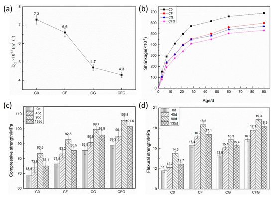
Figure 7. (a) Chloride migration coefficient of cementitious composite; (b) Drying shrinkage rate of specimens at different ages; (c) Compressive strength and (d) flexural strength of samples under the sulfate corrosion condition [7]. C0: control sample; CF: PVA fiber/cement; CG: GO/cement; CFG: GO/PVA fiber/cement.
When the cement materials are exposed to a low-humidity environment, water evaporation usually occurs from the capillary pores to result in the drying shrinkage [32]. The pore size determines the capillary force which holds the water in the capillary holes. Smaller pores are expected to induce larger capillary force. Therefore, the filling effect of GO will be instrumental to the suppression of shrinkage and the mechanical enhancement further increases the resistance of cement-based materials matrix to shrinkage. As a result, the 90-day shrinkage of GO/cement composite is found to decrease by 17.5% compared with control sample (Figure 7b). It has also been demonstrated that fibers play a role in restraining shrinkage by shear deformation along the interface [33]. The coupling effect of GO and PVA fiber minimize shrinkage in FRCC across all ages, as presented in Figure 7b.
Sulfate corrosion resistance of the modified cementitious composites over a period of 135 days is reflected by the measurements of compressive and flexural strength as shown in Figure 7c,d. Under sulfate corrosion conditions, the continuous hydration process is activated to produce more hydrates and compact mortar matrix, thus strengthening the cement materials. However, the sulfate corrosion process takes place at the same time, where the SO42− ions penetrate mortar and react with cement to produce intumescent minerals (e.g., ettringite), leading to the expansion stress and cracks in the mortar matrix. Based upon such a competing mechanism, the positive contribution dominates in the early stage of sulfate corrosion so that the mechanical strength is improved, whereas the negative factor becomes more prominent with the increase of corrosion time and finally the mechanical strength tends to decline [7]. Due to the increased impermeability with the presence of GO, the diffusion of the SO42− ions and the generation of intumescent minerals will be limited in the mortar matrix. On the other hand, both PVA fibers and GO serve to counteract the expansion stress and restrict the crack propagation in the cement. Hence, the GO/PVA/cement mixture exhibits the highest compressive and flexural strength among all the samples at 135 days.
2.4. Electrical Properties
Structural health monitoring of reinforced concrete structures has garnered enormous attention from both industry and academy, which aims to monitor the actual stress states and detect damages in the built infrastructure. Apart from using external sensors, the concept of cement-based piezoresistive sensors is registering an exponentially upward trend in recent years. The prerequisite is to produce conductive cementitious composites so the stress or damages can be detected by monitoring the change of electrical resistivity. In reality, the cement-based materials are anticipated to be slightly conductive due to the ion transfer, depending on the water content stored within the cement. The overall electrical conductivity of cementitious composites tends to be elevated by increasing the porosity and hence the interconnectivity [34]. However, in order to make cementitious composite as a conductive material, a more efficient approach is incorporating conductive fillers into the cement mixture, thus conferring their conductivity.
Due to the superior electrical conductivity of graphene, graphene-based cementitious composites have been reported to have outstanding electrical properties and self-sensing ability [35][36]. However, limited by the dispersion issue, GO instead of pristine graphene is more frequently used as fillers in cementitious composites, yet it is known to increase the electrical resistance due to oxygen-containing functional groups. Gopalakrishnana et al. [37] studied the electrical properties of cement composite by imposing GO on high-volume PVA fiber-reinforced Sugarcane bagasse ash (SCBA) mortars. As depicted in Figure 8a, compared to the control sample with electrical resistivity values of 6.1 and 7.2 KΩ cm at 7 day and 28 day curing ages, addition of GO and PVA increases the electrical resistivity for all the mixes. When the GO/PVA ratio reaches 1.5/1.0, the largest enhancement of electrical resistivity is observed, which is 79.5% and 77.6% at 7 day and 28 day curing ages. Due to the nucleation effect, the hydration process is accelerated with the presence of GO so that the densified microstructures result in the stumbling block of pathways in cement mortar, which are important for ionic conduction. In addition, GO has a high adsorption efficiency and decreases the availability of free water in cement, which is responsible for the improved electrical resistivity as well.
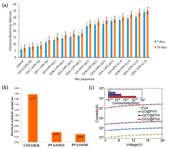
Figure 8. (a) Electrical resistivity of SCBA mortars with varied GO/PVA hybrid at the age of 7, 28 days [37] (Copyright permission Springer 2021); (b) Electrical resistivity of FRM with PVA/GO fillers [38] (Copyright permission Elsevier 2021); (c) Electrical conductivity measurement of oxidized graphene nanosheets-modified PVA fibers [4] (Copyright permission Elsevier 2020).
Nevertheless, Uygunoğlu et al. [38] reported an opposite observation on the same material composition, despite using a different preparation method of GO/PVA fillers. Therein, instead of direct mixing, they first prepared the GO/PVA composite ribbons and then mixed with cement and fly ash to obtain the composites. Consequently, a reduction of electrical resistivity was found for GO/PVA/mortar compared with control sample, as seen in Figure 8b. Increasing amount of GO from 0.012 g (GO12) to 0.036 g (GO36) further decreases the electrical resistance from 79.09% to 83.05%. One possible reason lies in the formation of the hydrogen bonds between oxygen-containing functional groups on GO and PVA. Even though PVA is insulating, it helps create large pores and enhance the electrical resistance of cementitious composite.
In this context, replacing GO with rGO fillers can be an effective way to increase the electrical conductivity of cement composites [11]. Upon removal of oxygen functional groups, the sp2-bonded clusters are partially restored, leading to an increase of carrier mobility of PVA fibers and correspondingly a change in their charge density. Figure 8c shows that the electric conductivity was boosted more than one order from 5 × 10⁻⁹ S/m for GO/PVA/cement to 10−7 S/m for rGO1/PVA/cement. Moreover, in contrast to rGO1-based composite which experiences 1 min reduction, longer treatment time (1 h) for rGO2/PVA/cement composite gives a more significant enhancement of conductivity (4 × 10⁻⁴ S/m), more than four orders higher than that of GO/PVA/cement sample [4].
2.5. Electromagnetic Interference Shielding Performance
With the advancement of modern technology, there has been a rapid growth of the electronic devices, which raise growing concerns over the electromagnetic pollution. Owing to the adverse impact of electromagnetic interference (EMI) and increased electromagnetic wave (EMW) within the atmosphere, it is imperative to provide EMI shielding for the infrastructure construction, especially for some particular buildings such as hospitals [39]. To this end, the development of cementitious materials with high shielding effectiveness (SE) has aroused tremendous attention, with a special emphasis on the addition of filler materials into the cement to enhance the SE.
Previous works have shown excellent EMI shielding effect of cementitious composites infused with graphene [40][41][42], having a huge potential spanning from the amelioration of electromagnetic emission problems on human health to the prevention of information leakage in the military field. Typical EMI shielding mechanism for the graphene-based cementitious composites can be summarized as: (1) Barrier effect of well-dispersed graphene to block EMW transmission; (2) Energy dissipation and frequency weakening of EMW during multiple reflection and refraction on randomly oriented graphene surface; (3) Absorption of EMW due to the dielectric characteristics of graphene [23]. While conductive fibers (e.g., carbon fibers and steel fibers) have been confirmed to help increase the EMI shielding performance of cementitious composite [43], the incorporation of graphene is believed to enhance the EMI SE to a higher level. For example, Chen et al. [2] introduced GO-deposited CF into cementitious composites and studied its enhancement of the EMI shielding performance. As seen in Figure 9a, apparently, the SE of CF/cement composite is rising with increasing amount of CF. A similar trend can be observed for GO-CF/cement as well in Figure 9b, while GO-CF presents an even more significant improvement in SE, especially when the mass fraction is beyond 0.2%. Particularly, at the mass fraction of 0.4%, SE of GO-CF/cement composite reaches as high as 34 dB, corresponding to a 278% increase than that of control sample without GO.
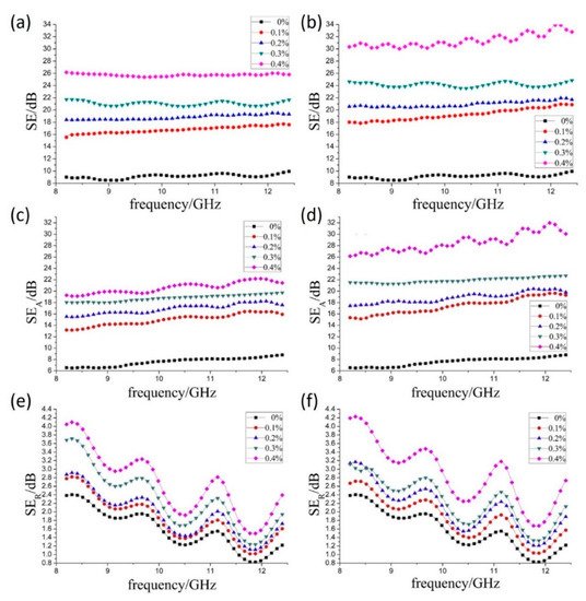
Figure 9. Variation of SE with frequency for (a) CF/cement and (b) GO-CF/cement composite with different mass fraction of fiber; Analysis of SEA for (c) CF/cement and (d) GO-CF/cement composite and SER for (e) CF/cement and (f) GO-CF/cement composite, respectively [2] (Copyright permission Elsevier 2015).
Generally, there are three major mechanisms involved in EMI shielding, including reflection (SER), absorption (SEA), and multiple reflections (SEMR), which are related to mobile charge carriers, electric (or magnetic) dipoles, and reflections at various surfaces or interfaces [44][45]. Mostly, the synergy effect among several shielding mechanisms contributes to the attenuation of EMW. As demonstrated previously, the multiple reflections and scattering are crucially important for shielding mechanisms, where EMW reflects at multi-interfaces in an EMI shielding material. However, when the SEA is larger than 10 dB, the SEMR can be insignificant [40]. Figure 9c–f display the SEA and SER results for CF/cement composite and GO-CF/cement composite, respectively. The SER values are within 2–4 dB for both composite systems; however, while the SEA for CF/cement composite is found to range from 7 to 22 dB, GO-CF/cement elevates it up to 30 dB at 0.4% content. It is hence concluded that absorption acts as the dominant mechanism in shielding. Furthermore, the higher SE achieved for GO can be originated from the defects and functional groups. On one hand, defects are considered as polarization centers. They can induce polarization relaxation under the alternating electromagnetic field and aid the attenuation of EMW [46]. On the other hand, carbon and oxygen atoms in the oxygen-containing functional groups have distinct electron capture capability, thus creating the electric dipole polarization. Under altering electromagnetic field, the electron motion hysteresis in these dipoles will cause extra polarization relaxation that facilitate the absorption [47].
According to Simon formalism [48], The EMI SE is also strongly dependent on the electrical conductivity of EMI materials. Although the defects and oxygen-containing functional groups of GO are responsible for EMI shielding, they disrupt sp2-bonded networks and endow GO with a relatively poor electrical conductivity compared with pristine graphene. In this scenario, rGO that partially restores the aromatic graphene structure looks more promising in EMI shielding performance, as it not only recovers electrical conductivity to build a more effective conductive network, but also retains structural features of GO which favor the dispersion of fiber as well as the polarization relaxation process [49]. Additionally, the wrinkled rGO sheets can increase the surface roughness of CF and trigger the mechanical interlocking effect within the cement. The conductive networks are reported to be robust enough to provide sufficient paths to transport charge carriers, which increases the shielding properties of the rGO modified FRCC composites [50].
References
- Yao, X.; Shamsaei, E.; Chen, S.; Zhang, Q.H.; de Souza, F.B.; Sagoe-Crentsil, K.; Duan, W. Graphene oxide-coated Poly(vinyl alcohol) fibers for enhanced fiber-reinforced cementitious composites. Compos. B Eng. 2019, 174, 107010.
- Chen, J.; Zhao, D.; Ge, H.; Wang, J. Graphene oxide-deposited carbon fiber/cement composites for electromagnetic interference shielding application. Constr. Build. Mater. 2015, 84, 66–72.
- Lu, Z.; Hanif, A.; Sun, G.; Liang, R.; Parthasarathy, P.; Li, Z. Highly dispersed graphene oxide electrodeposited carbon fiber reinforced cement-based materials with enhanced mechanical properties. Cem. Concr. Compos. 2018, 87, 220–228.
- Yao, X.; Shamsaei, E.; Wang, W.; Zhang, S.; Sagoe-Crentsil, K.; Duan, W. Graphene-based modification on the interface in fibre reinforced cementitious composites for improving both strength and toughness. Carbon 2020, 170, 493–502.
- Lu, Z.; Yu, J.; Yao, J.; Hou, D. Experimental and molecular modeling of polyethylene fiber/cement interface strengthened by graphene oxide. Cem. Concr. Compos. 2020, 112, 103676.
- Chen, Z.-S.; Zhou, X.; Wang, X.; Guo, P. Mechanical behavior of multilayer GO carbon-fiber cement composites. Constr. Build. Mater. 2018, 159, 205–212.
- Jiang, W.; Li, X.; Lv, Y.; Zhou, M.; Liu, Z.; Ren, Z.; Yu, Z. Cement-Based Materials Containing Graphene Oxide and Polyvinyl Alcohol Fiber: Mechanical Properties, Durability, and Microstructure. Nanomaterials 2018, 8, 638.
- Richardson, J.J.; Bjornmalm, M.; Caruso, F. Technology-driven layer-by-layer assembly of nanofilms. Science 2015, 348, aaa2491.
- Gadakh, D.; Dashora, P.; Wadhankar, G. A Review Paper on Graphene Coated Fibres. Graphene 2019, 8, 53–74.
- Zhang, Y.; Shen, Q.; Hou, J.; Sutrisna, P.D.; Chen, V. Shear-aligned graphene oxide laminate/Pebax ultrathin composite hollow fiber membranes using a facile dip-coating approach. J. Mater. Chem. A 2017, 5, 7732–7737.
- Chen, J.; Wu, J.; Ge, H.; Zhao, D.; Liu, C.; Hong, X. Reduced graphene oxide deposited carbon fiber reinforced polymer composites for electromagnetic interference shielding. Compos. A Appl. Sci. Manuf. 2016, 82, 141–150.
- Lin, Z.; Kanda, T.; Li, V.C. On interface property characterization and performance of fiber reinforced cementitious composites. Concr. Sci. Eng. 1999, 1, 173–174.
- Stang, H.; Li, V.C.; Krenchel, H. Design and structural applications of stress-crack width relations in fibre reinforced concrete. Mater. Struct. 1995, 28, 210–219.
- Chou, C.T.; Gaur, U.; Miller, B. Fracture Mechanisms during Fiber Pull-out for Carbon-Fiber-Reinforced Thermosetting Composites. Compos. Sci. Technol. 1993, 48, 307–316.
- Chua, P.; Piggott, M. The glass fibre—Polymer interface: I—Theoretical consideration for single fibre pull-out tests. Compos. Sci. Technol. 1985, 22, 33–42.
- Daly, M.; Cao, C.; Sun, H.; Sun, Y.; Filleter, T.; Singh, C.V. Interfacial shear strength of multilayer graphene oxide films. ACS Nano 2016, 10, 1939–1947.
- Cao, C.; Daly, M.; Chen, B.; Howe, J.Y.; Singh, C.V.; Filleter, T.; Sun, Y. Strengthening in Graphene Oxide Nanosheets: Bridging the Gap between Interplanar and Intraplanar Fracture. Nano Lett. 2015, 15, 6528–6534.
- Jancar, J. Review of the role of the interphase in the control of composite performance on micro- and nano-length scales. J. Mater. Sci. 2008, 43, 6747–6757.
- Constantinides, G.; Ulm, F.-J. The nanogranular nature of C–S–H. J. Mech. Phys. Solids 2007, 55, 64–90.
- Kong, W.; Kum, H.; Bae, S.H.; Shim, J.; Kim, H.; Kong, L.; Meng, Y.; Wang, K.; Kim, C.; Kim, J. Path towards graphene commercialization from lab to market. Nat. Nanotechnol. 2019, 14, 927–938.
- Wang, G.; Dai, Z.; Liu, L.; Hu, H.; Dai, Q.; Zhang, Z. Tuning the interfacial mechanical behaviors of monolayer graphene/PMMA nanocomposites. ACS Appl. Mater. Interfaces 2016, 8, 22554–22562.
- Yang, H.; Cui, H.; Tang, W.; Li, Z.; Han, N.; Xing, F. A critical review on research progress of graphene/cement based composites. Compos. A Appl. Sci. Manuf. 2017, 102, 273–296.
- Lin, Y.; Du, H. Graphene reinforced cement composites: A review. Constr. Build. Mater. 2020, 265, 120312.
- Chuah, S.; Pan, Z.; Sanjayan, J.G.; Wang, C.M.; Duan, W.H. Nano reinforced cement and concrete composites and new perspective from graphene oxide. Constr. Build. Mater. 2014, 73, 113–124.
- Zhou, G.X.; Li, C.; Zhao, Z.; Qi, Y.Z.; Yang, Z.H.; Jia, D.C.; Zhong, J.; Zhou, Y. 3D printing geopolymer nanocomposites: Graphene oxide size effects on a reactive matrix. Carbon 2020, 164, 215–223.
- Korniejenko, K.; Lin, W.T.; Šimonová, H. Mechanical properties of short polymer fiber-reinforced geopolymer composites. J. Compos. Sci. 2020, 4, 128.
- Ranjbar, N.; Mehrali, M.; Mehrali, M.; Alengaram, U.J.; Jumaat, M.Z. Graphene nanoplatelet-fly ash based geopolymer composites. Cem. Concr. Res. 2015, 76, 222–231.
- Zhong, J.; Zhou, G.X.; He, P.G.; Yang, Z.H.; Jia, D.C. 3D printing strong and conductive geo-polymer nanocomposite structures modified by graphene oxide. Carbon 2017, 117, 421–426.
- Xu, J.; Zhang, D. Multifunctional structural supercapacitor based on graphene and geopolymer. Electrochim. Acta 2017, 224, 105–112.
- Mehta, P.K.; Monteiro, P.J. Concrete: Microstructure, Properties, and Materials; McGraw-Hill Education: New York, NY, USA, 2014.
- Sanchez, F.; Sobolev, K. Nanotechnology in concrete—A review. Constr. Build. Mater. 2010, 24, 2060–2071.
- Aitcin, P.-C.; Neville, A.; Acker, P. Integrated view of shrinkage deformation. Concr. Int. 1997, 19, 35–41.
- Zhang, P.; Li, Q.-F. Effect of polypropylene fiber on durability of concrete composite containing fly ash and silica fume. Compos. B Eng. 2013, 45, 1587–1594.
- Madhavi, T.C.; Annamalai, S. Electrical conductivity of concrete. ARPN J. Eng. Appl. Sci. 2016, 11, 5979–5982.
- Yoo, D.-Y.; You, I.; Lee, S.-J. Electrical properties of cement-based composites with carbon nanotubes, graphene, and graphite nanofibers. Sensors 2017, 17, 1064.
- Bai, S.; Jiang, L.; Jiang, Y.; Jin, M.; Jiang, S.; Tao, D. Research on electrical conductivity of graphene/cement composites. Adv. Cem. Res. 2020, 32, 45–52.
- Gopalakrishnan, R.; Kaveri, R. Using graphene oxide to improve the mechanical and electrical properties of fiber-reinforced high-volume sugarcane bagasse ash cement mortar. Eur. Phys. J. Plus 2021, 136, 1–15.
- Uygunoğlu, T.; Şimşek, B.; Ceran, Ö.B.; Eryeşil, Ö. Novel hybrid fiber reinforced mortar production using polyvinyl alcohol with a blend of graphene oxide and silver nanoparticles. J. Build. Eng. 2021, 44, 102641.
- Wanasinghe, D.; Aslani, F.; Ma, G.; Habibi, D. Advancements in electromagnetic interference shielding cementitious composites. Constr. Build. Mater. 2020, 231, 117116.
- Singh, A.P.; Mishra, M.; Chandra, A.; Dhawan, S. Graphene oxide/ferrofluid/cement composites for electromagnetic interference shielding application. Nanotechnology 2011, 22, 465701.
- Long, W.-J.; Gu, Y.-C.; Ma, H.; Li, H.-D.; Xing, F. Mitigating the electromagnetic radiation by coupling use of waste cathode-ray tube glass and graphene oxide on cement composites. Compos. B Eng. 2019, 168, 25–33.
- Zhao, D.; Chen, J.; Gao, Q.; Ge, H.Y. Graphene oxide/cement composites for electromagnetic interference shielding. In Materials Science Forum; Trans Tech Publications: Stafa-Zurich, Switzerland, 2015; pp. 485–489.
- Zukowski, B.; dos Santos Mendonça, Y.G.; de Souza, J.V.B.; Toledo Filho, R.D. Cement-based EMI shielding materials. In Materials for Potential EMI Shielding Applications; Elsevier: Amsterdam, The Netherlands, 2020; pp. 333–340.
- Weng, C.; Wang, G.; Dai, Z.; Pei, Y.; Liu, L.; Zhang, Z. Buckled AgNW/MXene hybrid hierarchical sponges for high-performance electromagnetic interference shielding. Nanoscale 2019, 11, 22804–22812.
- Weng, C.; Dai, Z.; Wang, G.; Liu, L.; Zhang, Z. Elastomer-Free, Stretchable, and Conformable Silver Nanowire Conductors Enabled by Three-Dimensional Buckled Microstructures. ACS Appl. Mater. Interfaces 2019, 11, 6541–6549.
- Che, R.C.; Peng, L.M.; Duan, X.F.; Chen, Q.; Liang, X.L. Microwave absorption enhancement and complex permittivity and permeability of Fe encapsulated within carbon nanotubes. Adv. Mater. 2004, 16, 401–405.
- Paredes, J.; Villar-Rodil, S.; Martínez-Alonso, A.; Tascon, J. Graphene oxide dispersions in organic solvents. Langmuir 2008, 24, 10560–10564.
- Simon, R.M. EMI shielding through conductive plastics. Polym. Plast. Technol. Eng. 1981, 17, 1–10.
- Murugan, M.; Santhanam, M.; Gupta, S.S.; Pradeep, T.; Shah, S.P. Influence of 2D rGO nanosheets on the properties of OPC paste. Cem. Concr. Compos. 2016, 70, 48–59.
- Song, W.-L.; Cao, M.-S.; Qiao, B.-B.; Hou, Z.-L.; Lu, M.-M.; Wang, C.-Y.; Yuan, J.; Liu, D.-N.; Fan, L.-Z. Nano-scale and micron-scale manganese dioxide vs corresponding paraffin composites for electromagnetic interference shielding and microwave absorption. Mater. Res. Bull. 2014, 51, 277–286.
More
Information
Subjects:
Materials Science, Ceramics; Engineering, Civil
Contributor
MDPI registered users' name will be linked to their SciProfiles pages. To register with us, please refer to https://encyclopedia.pub/register
:
View Times:
1.5K
Revisions:
4 times
(View History)
Update Date:
09 Oct 2021
Table of Contents


Notice
You are not a member of the advisory board for this topic. If you want to update advisory board member profile, please contact office@encyclopedia.pub.
OK
Confirm
Only members of the Encyclopedia advisory board for this topic are allowed to note entries. Would you like to become an advisory board member of the Encyclopedia?
Yes
No
${ textCharacter }/${ maxCharacter }
Submit
Cancel
Back
Comments
${ item }
|
${ item.createdUser.fullName }
${ item.createdAt }
${ item.vote }
${ item.reply }
Delete
${ reply.createdUser.fullName }
${ reply.createdAt }
${ reply.vote }
Delete
There is no reply to this comment~
${ item.replyTextCharacter }/${ item.replyMaxCharacter }
Submit
Cancel
More
No more~
There is no comment~
${ textCharacter }/${ maxCharacter }
Submit
Cancel
${ selectedItem.replyTextCharacter }/${ selectedItem.replyMaxCharacter }
Submit
Cancel
Confirm
Are you sure to Delete?
Yes
No