The sensing requirements of the Oil & Gas industry for improved sensing in deeper zones include increased transmission length, improved spatial coverage and integration of multiple sensors with multimodal sensing capability. This imposes problems like signal attenuation, crosstalks and cross sensitivities. Optical fibre-based sensors are expected to provide superior sensing capabilities compared to traditional electrical sensors.
1. Introduction
In recent years, the recovery of hydrocarbons has become more and more difficult and challenging as exploration and production operations tend to seek new fronts into deep and ultra-deep harsh environments. As the energy demand continues to rise, there is a need for efficient management and optimization for production operations and systems to make this growing energy demand sustainable. This requires real-time monitoring of long and deep oil wells.
Sensors and sensing data are vital elements in the oil and gas (O&G) industry. O&G exploration and production have been moving into unconventional depths (more than 3 km) in order to meet the growing demand for energy
[1]. This results in harsh and extreme operating conditions, which are reflected by critical parameters like temperature, pressure, strain, etc. Therefore, reliable sensors which are able to continuously monitor current down-hole conditions have become very important in managing O&G reservoirs and wells
[2]. For efficient O&G resource management and enhanced oil and gas recovery, real-time and dynamic monitoring technologies are required
[3][4]. In order to satisfy this need, multi-point or distributed and multimodal simultaneous measurements will be advantageous for drilling and O&G production monitoring.
Exploration and production process monitoring helps to prevent or detect health and safety issues and to significantly enhance O&G production
[5]. Detecting and forecasting the conditions of the well at earlier stages have a considerable impact on Health, Safety and Environment (HSE), risk management, well control and cost-control strategies
[6]. It enables the oil well technicians and managers to take correct decisions in a timely manner
[7]. Continuous sensing and monitoring of unstable parameters like high temperature, pressure, strain, etc., are required in the O&G sector in order to protect and safeguard their valuable assets operating in the harshest and most challenging environments.
Current O&G sensing techniques are mainly based on electrical sensors, which have many constraints when used in adverse environmental conditions
[8]. These electrical sensors offer limited performance down-hole and are less reliable for real-time remote monitoring and control. Unfortunately, O&G reservoirs exhibit some of the harshest and least accessible environments on Earth
[9][10]. Increasing exploration depth results in High-Pressure High Temperature (HPHT) field conditions, which corresponds to temperatures above 205 °C/400 °F and pressures more than 138 MPa/20,000 psi
[11][12]. In such hostile habitats, conventional sensors either experience failure or operate poorly. This occurs mainly due to their inability to withstand high temperature and pressure, as well as corrosive and erosive environmental conditions, found within the oil wells. Other limitations of traditional electrical gauges include limited sensing range, single-point sensing capability and their inability to give continuous monitoring which makes them unsuitable for oil well real-time monitoring applications. In addition, their poor Signal to Noise Ratio (SNR) due to electromagnetic interference (EMI) and their considerable size makes them highly undesirable for in-well applications
[13]. On this account, improved technologies are to be developed to retrieve well information, in order to safely maximize oil productivity and reduce exploration and production cost, especially in the present situation of reduced crude oil prices.
Fibre-optic sensing technology can overcome the aforementioned limitations of their electrical counterparts, mainly due to their small size, electrical isolation, corrosion resistance, immunity to EMI and capability to operate in extreme environmental conditions
[14][15]. The small size of fibre-optic sensors facilitates them to be safely employed over longer distances with little or no future maintenance
[16]. Moreover, they have a reduced risk of failure when exposed to water or other reservoir and pipeline fluids and, also, they do not have any electrical power requirements at the sensor head
[17][18]. Another important advantage of fibre sensors is that the same optical fibre can handle dual functions. It can act as the sensing element for physical parameter measurement as well as the transmission medium for the sensed signal. This feature helps in the monitoring and sensing of different O&G critical parameters from remote locations
[19]. Furthermore, by exploiting the wavelength multiplexing capability of optical fibre, multi-point or distributed and multi-modal simultaneous measurements can be easily accomplished on the same fibre
[20]. Considering all these advantages, optical fibre sensing technology offers an attractive alternative to traditional electrical sensing technology for permanent monitoring of oil well reservoirs.
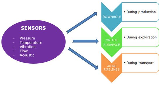
Sensing in the O&G sector involves the measurement of different parameters like pressure, temperature, vibration, flow and acoustics. Sensing should be carried out throughout all stages of O&G production, which means that the sensor should be active on the surface, along the pipeline and even in the down-hole. The measurements are to be taken throughout the well, from the surface to the total depth of the oil well reservoir
[2].
Figure 1 shows the various stages where sensors are required in the O&G industry.
Figure 1. Sensor requirements in the O&G industry.
The elemental part of optical sensor design is the identification of the key technology which best suits the needs of the O&G industry. There are different optical sensing methodologies, but the selection needs to be carried out considering the environmental conditions, application (downhole, on the surface or along the pipelines), level of sensitivity and accuracy required in physical parameter measurements.
With the worldwide decrease in oil reserves, exploitation of challenging reservoirs has rapidly started. In comparison to standard wells, the overall production of such reservoirs entails high and complex performance instrumentation, for example, fibre-optic distributed pressure, distributed strain monitoring, distributed temperature monitoring, etc. The development of fibre-optic sensory technology with regards to the oil and gas industry is currently on the rise and represents the future of well monitoring. Monitoring and data transmission via the utilization of fibre-optic sensors and standard optical fibre in cabling is currently common in the refining of natural gas and standard crude oil throughout the world. With the trend of hydrocarbon consumption outpacing its given discovery, techniques in Enhanced Oil Recovery (EOR) are being deployed worldwide so as to increase the apparent recoverable assets in the known reservoirs. Fibre-optic Monitoring represents an opportunity for the current oil and gas industry to manage and subsequently optimize its resources in a more effective manner and provide real-time data in a continuous way without interrupting production and reducing well intervention. Visiongain had forecasted that the expected expenditure on Fibre-Optic Monitoring by the gas and oil industry will be increasing globally
[21]. The rise of relatively expensive multi- lateral hydraulic fracturing, the continued strength of the given capital expenditure for EOR and the intense focus on improving oil recovery make provision for the main markets for the uptake of Fibre-optic Monitoring over the next 10 years
[21]. Although this exquisite technology has been around for a significant period, researchers are still investigating relatively new ways that this technology can withstand relatively higher temperatures and significant pressures with little disruption. Furthermore, the application opportunities within the current oil and gas industry for fibre-optic monitoring are poised to enable a considerable growth in spending on fibre-optic monitoring equipment. Increased digitization in the oil and gas industry has led to an increase in the use of fibre-optics sensing systems for production and pipeline monitoring. The global DAS market is projected to reach USD 792 million by 2025 from USD 513 million in 2019, which is considered to be an impact of COVID-19
[22].
2. Optical Fibre-Based Sensors
An optical fibre sensor is composed of an optical fibre, transducer or a sensing element, detector and a light source
[23]. Optical fibre is the medium through which light can propagate and the underlying principle is total internal reflection.
Fibre-optic sensing technology has several inherent advantages which makes them very attractive for a wide range of industrial sensing applications. The optical fibre is typically made up of a cylindrical waveguide that consists of a thin core with a refractive index covered by a cladding layer with a refractive index usually lower than that of the core for a single-mode fibre (SMF).
An SMF is made up of the core and cladding layers which are usually from fused silica. Light is propagated through the core of the fibre by total internal reflection (Snell’s law)
[24] and to achieve a high refractive index, the core of the fibre is usually doped with germanium. To allow for the light energy to be maintained within the core, the refractive index of the core must be greater than that of the cladding. Multimode fibre has a larger core diameter that allows multiple modes of light to propagate. Photonic Crystal Fibres (PCFs), also known as microstructured fibres, represent another class of optical fibre that has a specialised geometrical structure (core-air hole cladding) and unique properties like guiding mechanisms and modal characteristics, making them an interesting candidate for a range of applications. To analyse polarisation effects, special fibres with modified core or cladding structures are needed. Polarisation fibres guide only one polarisation direction, thus polarising light is propagated through the fibre.
Standard telecom fibres are protected by coatings/buffer which protects the optical fibres from mechanical and environmental stresses. The primary coatings are applied on single or dual layers. The buffer material provides an additional layer of protection. For industrial applications like oil and gas, with harsh environments/HPHT (High-Pressure High Temperature) field conditions, special polymer coatings like polyamide
[25][26][27] and acrylate
[28] coatings are used which considerably increases the sensor sensitivities to temperature and strain. Standard coatings on the other side are not specified for environmental parameters, which can differ from the conditions in a downhole
[29].
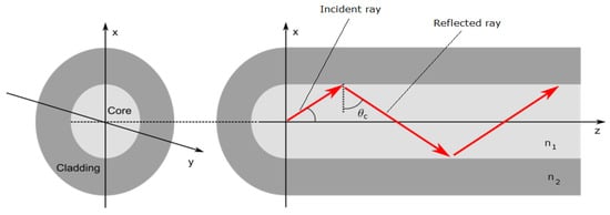
Figure 2 illustrates the light propagation through an optical fibre. If the angle of incidence of the incident ray is greater than the critical angle (θc) then the light ray gets reflected and confined within the core, else it is refracted. The critical angle is defined by Snell’s law and is given by:
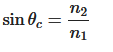
where n1 and n2 corresponds to the core and cladding refractive indices, respectively.
Figure 2. Schematic of light propagation through an optical fibre.
PCFs are a special class of optical fibres with a complex refractive index profile that employs a microstructured arrangement of low-index material in a background material of higher refractive index
[30]. Normally the background material used in PCFs are pure or undoped silica and the low index cladding region consists of many air voids, also known as air holes
[31]. Typically, photonic crystals are periodic optical (micro or nano) structures running axially along the length of the optical fibre, which affect the propagation characteristics of the electromagnetic waves travelling through its core
[32].
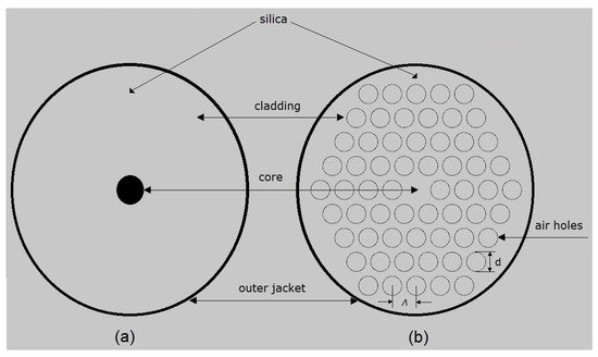
Figure 3a,b show the cross-sectional view of the structural difference between a standard step-index SMF and a solid core PCF with microstructured cladding. The geometrical parameters of PCF comprise: pitch (Λ)
which is the cladding hole centre to centre distance and the diameter of the cladding air hole (d)
.
Figure 3. Cross-section of: (a) step-index SMF and (b) solid core PCF.
Optical fibres can be used as sensors for sensing various physical parameters like temperature, pressure, strain, etc., wherein the parameter to be sensed modulates various properties of light. From the basic principle of light propagation through an optical fibre, the light propagation changes when subjected to varying environmental conditions such as temperature and strain. By analysing the changes of the light properties through the fibre, the environmental conditions themselves can be determined. Fibre-optic sensors have been designed and developed to measure a wide range of physical parameters such as pressure
[33], temperature
[34], position
[35], etc. Light propagated through an optical fibre can be characterized by parameters such as intensity, phase, wavelength and polarisation. The detection of the changes of these parameters as the optical fibre interacts with external perturbations can lead to the design of optical sensors capable of measuring a variety of physical parameters. As a result, fibre-optic sensors can be based on intensity measurement, phase (interferometric) measurement, spectral (wavelength), polarisation modulation and also the physical quantity they measure and their effect on the electric field of the optical signal. Existing optical fibre sensing technologies are categorised based on the effects used to measure physical phenomena and also the light modulation techniques used. In optical fibre sensors information is conveyed as a variation in intensity, frequency, phase, polarisation, wavelength or their combination of light
[36]. Optical fibre sensing techniques like Raman
[37], interferometry (Fabry-Perot, Michelson)
[38][39][40], fibre Bragg gratings (FBG)
[41], Brillouin
[42], etc., are proficient to monitor different physical parameters such as pressure, temperature, strain, chemical concentration, flow, etc. Extensive research into the advancement of optical fibre technology for variety of applications have been ongoing for the past 30 years which have laid the technical background for the various categories and their applications are expanding rapidly.
Fibre-optic sensors are further divided into two subcategories: intrinsic and extrinsic sensors. For intrinsic sensors, the light is confined within the optical fibre in which the physical quantity acts on. The performance of intrinsic sensors is largely dependent on fibre materials. While for extrinsic sensors, the light exits the fibre, get modulated by the external perturbation and is relaunched back into the fibre. The performance, in this case, is largely independent of the fibre material but on the sensing element.
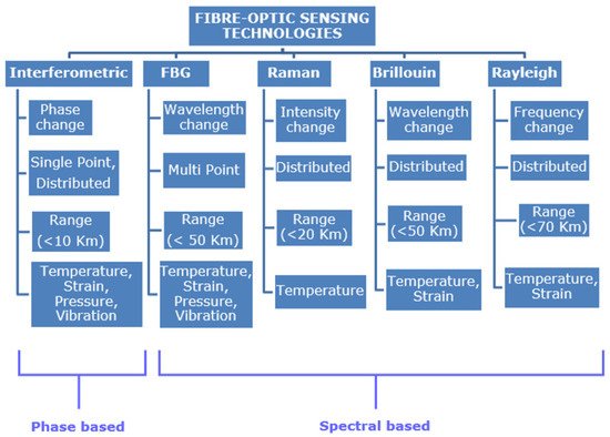
Figure 4 shows the comparison between different optical fibre sensing technologies
[38][39][40][41][42][43][44]. The various sensors compared in
Figure 4 are all intrinsic type fibre-optic sensors.
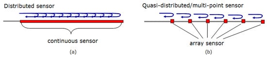
Figure 4 compares the most widely used fibre-optics sensors, however, there are other categories like polarisation-based sensors, Distributed Chemical Sensors. Distributed fibre-optic sensor (
Figure 5a) enables continuous measurements along the entire length of the sensing fibre, whereas quasi distributed or multi-point sensors (
Figure 5b) carries out sensing along specific points of the fibre sensors. Multimodal fibre-optic sensors are capable of sensing multiple sensing modalities like phase, wavelength, polarisation, etc., which can be utilised for multi-parameter sensing. Multi-parameter sensing involves sensing multiple parameters, which can be physical parameters like temperature, pressure, vibration, etc., or chemical parameters.
Figure 4. Comparison of fibre-optic sensing technologies.
Figure 5. (a) Distributed fibre-optic sensor and (b) quasi-distributed fibre-optic sensor.
3. DFOS in the Oil and Gas Industry
3.1. Distributed Temperature Sensing (DTS)
The DTS use the OTDR operating model based on Raman scattering in the optical fibre
[45], which transduces temperature into an optical signal. The DTS box beams laser lights along the optical fibre sensor in pulses. The travelling light pulses experience scattering with some of the lights directed back to the DTS box, Raman backscattered light, which comprises two bands: anti-Stokes and Stokes. The intensity of the anti-Stokes band changes with temperature while the other remains constant. By calculating the intensity of the ratio of the anti-Stokes backscatter and the Stokes backscatter we are able to obtain the temperature in the fibre. The temperatures are not recorded at points, but they are recorded along the cable that serves as the optical sensors. They can measure temperatures of up to 300 degrees Celsius per meter
[46]. Using conventional OTDRs, a range of approximately 15 kilometres can be obtained for the DTS
[47]. The DTS resolves both its temporal and spatial temperatures at 0.1 degrees Celsius. It has also a spatial resolution of 1.5 m
[45].
Typical well monitoring applications of the DTS include flow metering, flow assurances, leak detection, gas-lift surveillance, and permanent temperature logging
[48][45].
3.2. Distributed Acoustic Sensing (DAS)
The DAS uses optical fibre for sensing and telemetry. The DAS is an OTDR-based system that uses Rayleigh backscatters in a single-mode optical fibre to measure sound frequencies over large distances and in harsh environments. It is mostly used in the sensing of strains in well systems. Using an acoustic-based system allows the operators to reconstruct the source event and subject it to real-time analysis. The optical pulse that is propagating along the fibre experiences attenuation along the optical fibre. The acoustic signals obtained from each position along the fibre from the processed backscattered light are then analysed and sent to a display
[49].
The DAS system is ideal for the detection of relative strains wherein the operators use the optical fibre’s index of refraction and speed of light to determine the distance along the fibre that is experiencing the strain. However, the accuracy of the measurement is dependent on the distance that the light probe travels. For this reason, the DAS system pulses the light strobe a thousand times per second to obtain a high signal to noise ratio
[50]. The carrier level is determined by the signal amplitude while the noise is determined by combining different sources including the detector, electronic components, and laser light pulses. The maximum operational range of the DAS is limited when the pulse’s amplitude becomes very low to the extent that it cannot be able to send a clear signal. An increase in the power of the input signal cannot remedy this decline of the maximum range. Exceeding the recommended maximum range will result in non-linear optical effects that are eventually disruptive to the entire optical fibre system. The DAS system’s effective fibre length is 10 km. The spatial down sampling is equal or less than 1 m while the frequency range is up to 10 kHz
[51].
DAS is preferable in wellbore diagnostics to monitor various factors. It can be used to determine the location of a leak flow caused by pressure bleeding. It can differentiate a single-phase flow from a two-phase flow. The peak noise can estimate the rate of leaking. The system can also distinguish between the matrix flow, borehole flow, fracture flow, and channelling
[50]. The appropriateness of the DAS system in these operations is due to the following factors. First, the low acoustic frequencies enable the DAS system to provide a continuous full wellbore coverage
[52]. Second, the acquisition of operational data from an entire well takes only minutes. Third, the costs of deployment are low. Fourth, the DAS system is safer because one is not required to rig up for logging.
3.3. Distributed Temperature and/or Strain Sensing (DTSS)
The DTSS is based on the Brillouin scattering mechanism that employs the OTDR system. The system analyses both the thermal and strain effects of the target object by combining both the DTS and the DSS system. The DTS measures temperature properties while the DSS provides measurements that are used to the location and severity of deformation in well casing. The DSS also provides insightful data that estimate the stresses inherent at perforations during oil output stimulations. Most DTSS systems are based on the technology that combines the Brillouin Optical Time Domain Reflectometer (BOTDR) with the Brillouin optical time-domain analysis (BOTDA). The BOTDA preceded the BOTDR in sensor detection. It used two lasers that counter-propagate by exploiting the benefits of Brillouin amplification. However, the system was limited to a temperature accuracy of 3 degrees Celsius and a spatial resolution of 100 m over a sensing length of 1.2 km. The BOTDR was introduced because it could monitor the system from the opposite end
[53]. As a result, the 1.2 km limitation in the temperature measurement range was increased to approximately 11 km without a change in the temperature accuracy or spatial resolution. An optimally tuned DTSS system can have a maximum temperature measurement range of over 50 km.
The DTSS system is ideal because it can use loop or single end measurements
[54]. For that reason, the failure of the BOTDA part of the system is not a worry because the system switches to the more stable BOTDR system. Second, the system is affordable because it uses a low-cost telecoms fibre that is capable of detecting both temperature and strain. Third, the system has a high spatial resolution and range. Fourth, the combination of the BOTDA and the BOTDR system enables the operator to monitor a well using multiple channels. These features make the DTSS system ideal for the monitoring of a leakage in a well for distances of up to 140 km.
3.4. Distributed Pressure Sensing (DPS)
The core principle of DPS is the conversion of hydrostatic pressure acting along a coated optical fibre, into a distributed mechanical strain
[55]. Measurements of distributed pressure can be thus inferred by converting the applied hydrostatic pressure into distributed mechanical strain acting on the fibre, and measuring the strain changes by the Brillouin scattering frequency shifts they experience
[56].
The DPS is preferable because it does not require expensive optical devices. A light source and a light detector are the main elements that are needed in this technology. However, the DPS has some inefficiencies based on the intrinsic nature of the measurements. For example, the intensity of light often depends on quite a number of factors that cannot be controlled easily or cannot be controlled at all. The light source’s intensity of light is often subject to fluctuations because of certain factors such as temperature changes and ageing
[57]. Oxidation can also affect the efficiency of the reflectivity of the diaphragm mirror. The aspect of fibre bending with the objective of increasing power input can also affect the intensity of the light that is being emitted. This disadvantage is always corrected by fixing the pathway of the fibre-optics. However, compensations are always made while calibrating the pressure sensor system. It is important to note that these provisions meant to accommodate the errors mentioned above are subject to bias and can question the accuracy of the system. Zhang et al. reported an ultra-high sensitivity distributed pressure sensor with a sensing range of 1.05 km and a spatial resolution of 5 cm
[58].
3.5. Distributed Chemical Sensing (DCS)
Chemical sensors in fibre-optics operate in a manner that allows the transportation of the light by intensity or wavelength in order to provide vital information concerning the analytes in the immediate environment that surrounds the sensor
[59].
A distributed chemical sensor is normally developed by coating multiple Bragg gratings in a single glass fibre with chemical responsive coatings. In this configuration, FBGs are quasi-distributed or distributed point sensors.
A chemically selective layer is used to replace a part of the fibre’s cladding. The layer detects the environment in terms of light polarisation, reflectance, and absorbance changes. The light or propagation characteristics of the optical fibre measure the changes in the target object. Typically, the DCS is vital in the detection of formation water, enhanced oil recovery water breakthrough, H
2S and the CO
2 in carbon capture reservoirs and approximating the identity of specific molecules in diverse media and under extreme conditions. A DCS modified by the coated fibre Bragg grating will produce an axial strain in the fibre in the presence of a chemical compound
[51]. The measurement of the different chemical compositions is feasible if different coatings are applied on the FBG coats. This coating has a reversible absorption property because it repels water and absorbs the target analyte. The presence of a chemical compound will induce a wavelength shift of the FBG.
However, this shift is only useful in determining the quantitative properties of the chemical compound. The accuracy of the results is also prone to external factors such as coating sensitivity, methods of processing the coating to the FBG, and the approach used to optimize the chemical selectivity of the polymeric coatings. For that reason, the selective measurement of a particular chemical compound will require the operator to tune the polymer coating on the FBG to suit the analytes
[60].
4. DTS for Oil and Gas Well Monitoring
In recent times extracting oil and gas from reservoirs comes with unique challenges, increase in demand for energy with a shortage of oil produced has driven the petroleum industry to search for oil in more complex reservoirs. Due to the complexity of these reservoirs, the strategy for oil production has become more difficult and often economically impossible utilizing available technology. Reliable and efficient data are required for making decisions to combat the issues with uncertainty. Fibre-optic DTS based on the principle of Raman backscattering is more efficient for oil and gas well monitoring than conventional electronic sensors. However, one critical issue associated with the DTS system is the complexity in the intensity of the backscattering profile; this is as a result of local attenuation affected by physical perturbation as well as pure temperature effect
[61]. Differential attenuation (DA) in optical fibre is the gradual loss of backscattered light intensity as it moves through the fibre back to a detector system. To achieve accurate temperature measurement, the DA in the optical fibre must be resolved by correcting this error in the DTS system. The attenuation error in a fibre-optic cable is due to the difference in wavelength of Stokes and anti-Stokes component which again depends on the laser pulse
[62].
Fibre cable produced by manufacturers has different attenuation rates; attenuation can be enhanced during installation or thereafter by bending or twisting of the fibre cable, tension and chemical ingression of hydrogen gas which is very common in the oil and gas industry
[63][64]. These conditions result in non-linear attenuation along the fibre cable which causes error in measurement when a single-ended configuration is applied
[64]. A double-ended configuration of fibre cable addresses the issues with nonlinear attenuation by looping the cable across an area of consideration and connecting both ends of the loop to a DTS system. The result of the experiment conducted showed similar accuracy when compared with single-ended configuration with linear attenuation. However, twice the length of fibre cable is needed for this system (as compared to the single-ended configuration) when applied in an oil or gas well
[64].
Furthermore, in the event of hydrogen darkening optical transmission capability of the fibre is limited. Space limitation can also pose a huge problem. Hence this method cannot be applied in all wells. Increased noise in temperature trace is prominent in the double-ended system due to the long length of fibre cable and consequently requires more time for data acquisition during measurement to reduce the noise level.
Another typical way in which this problem could be resolved is by sectioning out areas in the optical fibre cable known to have nonlinear attenuation and applying the Differential Attenuation Factor (DAF) for each section
[65]. The issue with this method is that fibre condition changes over time and the attenuation rate of these sections will change as well hence it will require sectioning the fibre and making a correction on the DAF constantly.
This method may not be practical in cases where the attenuation rate changes continuously in wells. In instances where the fibre is installed in a well, acquiring the correct value for DAF will be difficult or impossible in most cases because the temperature at the end point of the fibre is required to obtain the DAF using this method
[62].
The possible alternative to resolving these issues is the deployment of a single-ended optical cable configuration which can achieve the same accuracy as the double-ended configuration. DTS system works with the principle of Raman scattering for temperature measurement. The Raman signal has two bands, namely Stokes and anti-Stokes bands. To carry out this correction using a single-ended system, an extra light source is needed with a wavelength chosen in which the Stokes wavelength of the secondary sources (correction light source) coincides with the backscattered anti-Stokes wavelength of the primary source (measurement light source). The Stokes and anti-Stokes signals filtered from the two light sources produce the same attenuation rate during backscattering. This technique cancels out the DA automatically ensuring temperature measurements are accurate.
 +1 point