- Introduction
Energy is an essential requirement for our daily life and sustainable development of our modern society. Energy is required in transportation, communication, aviation, and it also powers our computers, TVs, mobile phones, washing machines, air conditioners, and numerous other electrical and electronic devices. In the past few decades, the rapid industrialization, urbanization, and population growth has increased the demand for energy, leading to the overweening consumption of fossil fuels, which downscales the fossil reserves. The growing global warming, climate change, and diminution of energy reserves led to devoted research towards sustainable and renewable energy sources. As per the 2018 BP (British Petroleum) Energy Outlook, renewable energy is the fastest growing energy source, which accounts for 40% of the increase in energy [1]. Bioenergy, hydropower, solar, and wind are some of the well-established renewable energy sources that help to attain the need for energy at mega to gigawatts power scale. In the past decades, energy-harvesting techniques have drawn the limelight with the expansion of the Internet of Thing (IoT), sensors, wearable, and portable electronics, mobile phones, automatic security systems, defense technologies, etc., because they require power sources that are perpetual and free of maintenance. Generally, such devices rely on batteries for a power source, which has a limited life and environmental hazards. In this regard, harvesting the ambient mechanical energy to power up these devices could be a better choice. Ambient mechanical energy is abundant and the most significant form of renewable energy source among other sources in the environment [2–4]. There is a lot of potential in human body motions that can be effectively converted to electricity [5] (Table 1).
Table 1. Energy potential in human body motions [5].
|
Body Motions
|
Mechanical Energy
|
Available Electrical Energy
|
Electrical Energy Per Movement
|
|
Blood Flow
|
0.93 W
|
0.16 W
|
0.16 J
|
|
Exhalation
|
1 W
|
0.17 W
|
1.02 J
|
|
Inhalation
|
0.83 W
|
0.14 W
|
0.84 J
|
|
Upper Limbs
|
3 W
|
0.51 W
|
2.25 J
|
|
Walking
|
67 W
|
11.39 W
|
18.90 J
|
|
Fingers Typing
|
6.9–19 mW
|
1.2–3.2 mW
|
226–406 mJ
|
This report aims to provide a comprehensive review on piezo-, tribo-, and pyro-based nanogenerators as sustainable energy-harvesting devices including the evolution, development, and applications of the nanogenerators in the past decade. The review is limited to materials used in nanogenerators, the corresponding growth in their electrical output, and their applications in harvesting various ambient energies over the years. The history and general overview of the development of nanogenerators are introduced in Section 2. Then, the working, output power performance, and applications of piezoelectric nanogenerators are summarized in Section 3.
- History and Development of Nanogenerators
Nanogenerators are generally an energy-harvesting device that generate electricity from waste mechanical energy from the ambient. Earlier, by the end of 17th century, scientists developed practical means to generate electricity from friction. The primitive form of friction machine was developed around 1663 [6]. Later, several researchers worked on this machine to establish the performance. In 1831, the electromagnetic generator was discovered, which is the widely used generator in thermal power plants still today. In 1878, the Wimshurst machine based on static electricity was discovered, which became a popular static electricity generator. In 1929, the famous Van de Graaff generator was invented, which produces very high-voltage direct current. The modern Van de Graaff generators can achieve the very high potential of up to 25 megavolts. Later, technologies were developed to generate electricity based on piezoelectric, triboelectric, and pyroelectric by applying nanotechnology. The high surface area and tunable physical and chemical properties of nanoscale structures promise significantly more efficient technologies that can capture, convert, and store different forms of energy like thermal, radiant, electrical, chemical, and mechanical [7]. The crucial inventions in the history of mechanical energy harvesting are shown in Figure 1a. The energy requirement of various devices at various power scale is represented in Figure 1b.
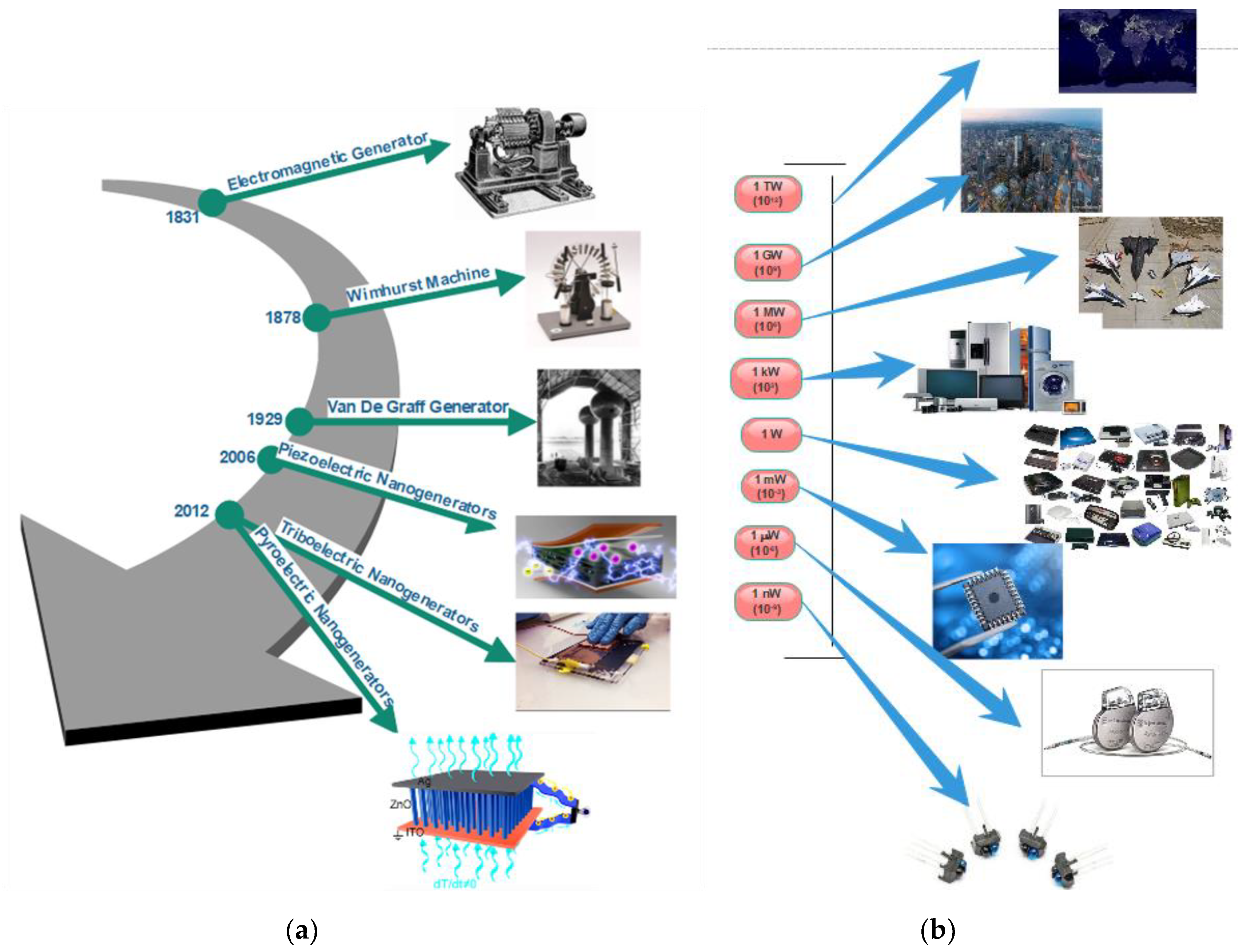
Figure 1. (a) The major inventions in the history of mechanical energy-harvesting technology. (b) Energy required for various devices at various power scales.
So far, there are several ambient energy-harvesting techniques that have been utilized based on the piezoelectric effect, triboelectric effect, pyroelectric effect, and electromagnetic induction, which converts mechanical energy into electricity. Nanogenerators are an evolving energy-harvesting technology that can harvest various classes of mechanical energy such as human motion (i.e., walking, breathing, running, heartbeat), vibration, flowing water, raindrops, and wind; even waste heat can be converted into electricity (pyroelectric effect). The first nanogenerator was developed by Wang et al. in the year 2006 using ZnO nanowires based on the piezoelectric effect, which has a power conversion efficiency of 17–30% [8].
There are some available techniques like traditional cantilever-based resonators and transducers to convert mechanical vibrations into electricity but they work effectively for high-frequency vibrations only; on other hand, nanogenerators can be made at nanoscale so that they can effectively harvest the low-frequency mechanical vibrations. In the case of ZnO nanowires, it can be bent more than the bulk ZnO without any damage, making it possible to withstand more strain, and so generates more electricity [8,9]. The different types of nanogenerators and their applications are illustrated in Figure 2. The nanogenerators have shown higher potential and several innovative platforms for mechanical energy harvesting and self-power sensing and monitoring. As technology is growing, there is also a sharp increase in the number of publications in the field of nanogenerators. As per the source of Science Direct database, there are around 469 publications in the year 2018 alone, which is 1.5 times higher when compared to 2017. Figure 3 shows a steady increase in the growth of research in the field of nanogenerators.
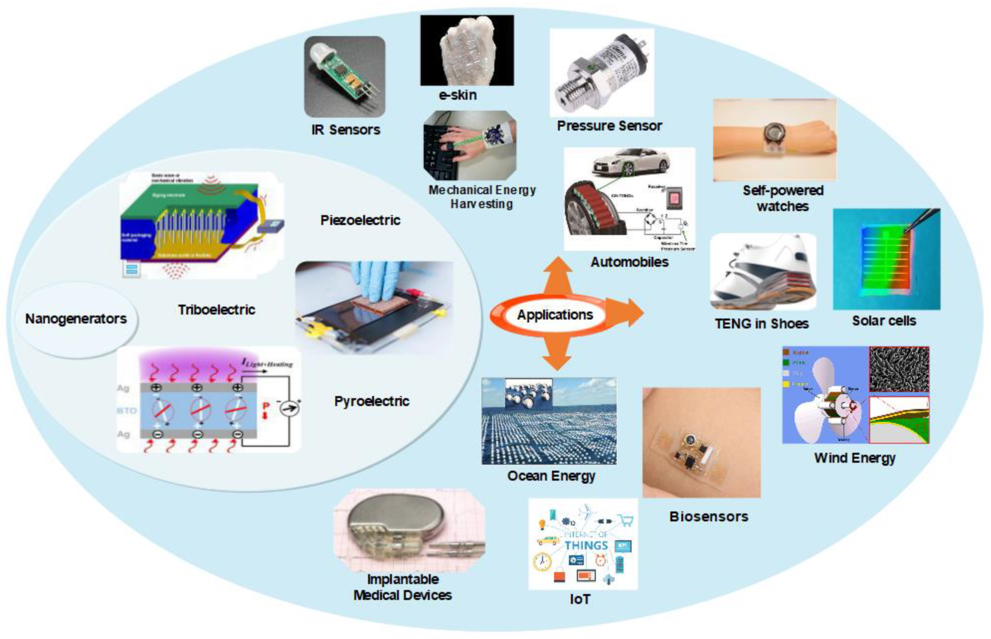
Figure 2. Different types of nanogenerators and their applications in the era of the Internet of Things (IoT).
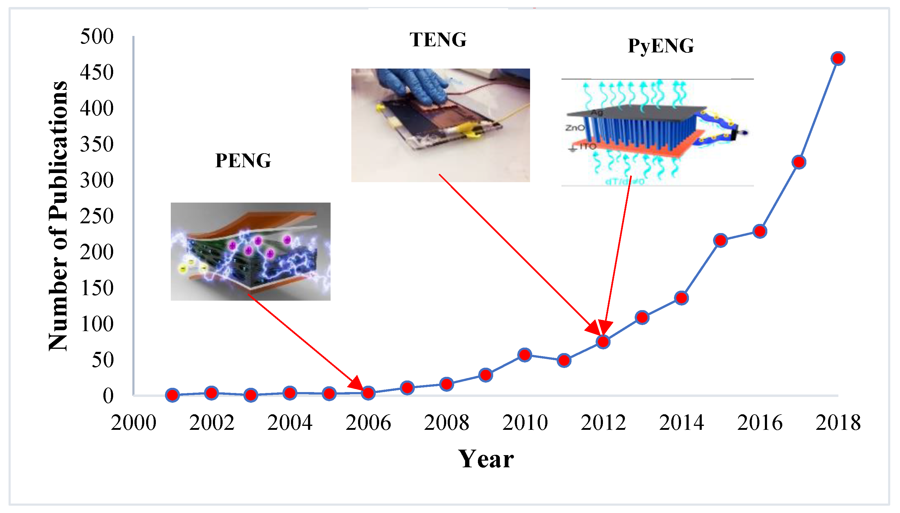
Figure 3. The number publications in the field of nanogenerators over the years.
3. Nanogenerators Based on Piezoelectric Effect
Piezoelectric nanogenerators (PENG) work on the principle of piezoelectric effect, which means electricity generation when subjected to mechanical stress. In PENG, two electrodes with balanced fermi levels on a piezoelectric material are subjected to an external strain, which creates a piezo potential difference between the internal and external Fermi levels (highest energy state occupied by the electrons) at the contacts [2,8,10–15]. To balance this difference in Fermi levels, the charge carriers flow through the external load and a balanced electrostatic level is reached. Alternatively, applying an electric field on a piezoelectric material can cause a mechanical strain. There are two cases of PENG [11,16], one where the individual nanostructure (nanowire/nanorod) [17] is subjected to the strain exerted perpendicular to the growing direction of the nanowire/nanorod, which leads to the generation of the electric field. Figure 4a shows the working of PENG when the force is applied perpendicular to its axis. When a force is applied perpendicular to the direction of the axis of the nanostructure using atomic force microscopy probe, one portion of the nanostructure is stretched (positive strain) while the other undergoes compression (negative strain) [8]. The stretched surface with positive potential was first contacted by the probe, and at this interface, the bias voltage is negative. Thus, a reversed bias Schottky diode is formed with little current. When the probe contacts the compressed side of the nanostructure with negative potential, a biased positive voltage is formed at the interface with sharp peak output current as driven by the potential difference between the two sides. The current flow due to the ohmic contact formed at the bottom of the nanostructure finally re-balances the electric field generated at the tip [8,11]. The conduction is possible only when the top electrode is in contact with the negative potential, whereas no current will be generated if the top electrode is in contact with the positive potential. This is the case for n-type semiconductive nanostructures; in the case of p-type semiconductive nanostructures, it will exhibit the reverse phenomenon since the hole is mobile in this case. The other case is where the external strain is exerted parallel to the growing direction of the nanostructures (Figure 4b). When the force is applied to the tip of the laterally grown nanowire which is stacked between the Schottky contact and ohmic contact, a uniaxial compressive is generated in the nanowire. The tip of the nanowire will have negative potential and increases the Fermi level due to the piezoelectric effect. As the electrons flow from the tip of the nanowire to the bottom through the external circuit, positive potential will be generated at the tip. The Schottky contact blocks the flow of electrons through the nanowires and instead passes the electrons through the external circuit. When the applied force is removed, the piezoelectric effect diminishes immediately and a positive potential at the tip gets neutralized because of the migration of electrons from the bottom electrode to the top, which produces voltage peak in the opposite direction. Due to the in-situ rectifying effect of the Schottky contact, the detected output exhibits direct current characteristics [14].
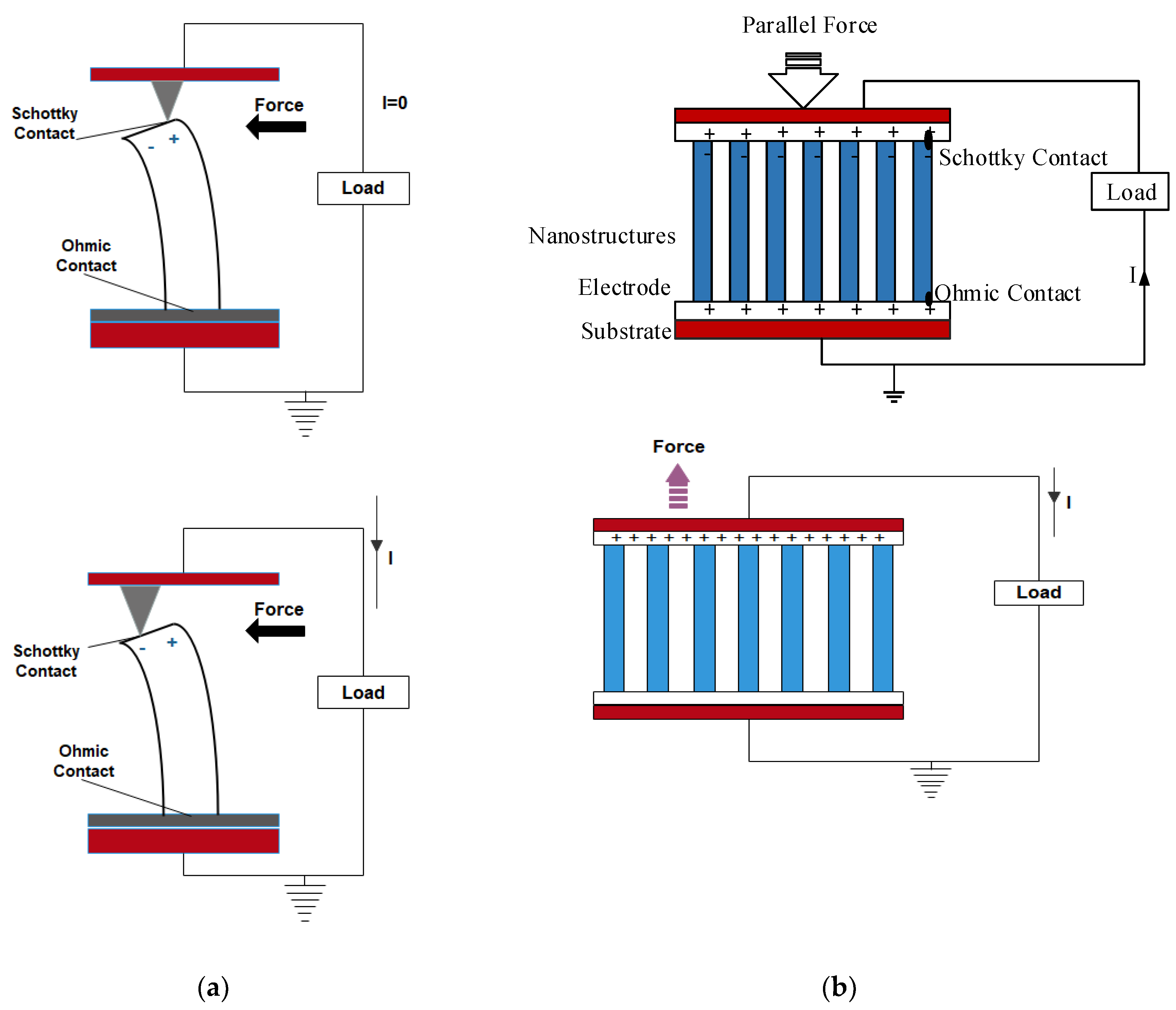
Figure 4. (a) Force exerted perpendicular to the growth of the nanowire. (b) Force exerted parallel to the growth of the nanowire.
In their work, Zhu et al. replaced this Schottky contact with PMMA layer to create a potential barrier for charge accumulation [
18]. In this nanogenerator, when compressive force is applied, a piezopotential field is generated along the nanowires. As a result of electrostatic force, inductive charges accumulate on the top and bottom of the electrodes. This is similar to capacitive configuration in which the strained nanowires can be compared with polarized dipole moments in a plate capacitor filled by a dielectric material. Once the applied stress is released, the piezopotential disappears and the electrons flows back through the external circuit [
18,
19]. AC output is observed in the cases of capacitive configuration and when the Schottky diode is a series resistance in the piezoelectric nanogenerators.
To effectively enhance the output power of the PENG, several nanowires are stacked together to effectively synchronize the voltage output of each nanowire. Two effective integrations of nanowires were developed by Wang et al. [
11,
16]; one is vertical-nanowire-integrated nanogenerator in which the vertically grown nanowires are stacked together (a). The working mechanism of vertically integrated PENGs includes lateral bending and vertical compression of nanowires as explained earlier. The other one is the lateral-nanowire-integrated nanogenerator, in which the parallelly grown nanowires are stacked together in the nanogenerator (b). In laterally integrated nanogenerators, the deformation of nanowires is always caused by lateral bending either by bending the substrate or by applying pressure on the radial direction of the nanowires [
20]. The uniform lateral bending of nanowires can be regarded as the lateral stretching by neglecting the strain distribution in the radial direction due to the ultra-high aspect ratio of the 1D nanostructures. In a study, the energy conversion efficiency of both laterally stretched nanowire and vertically compressed nanowire were compared, and the results showed that the laterally bent nanowire could generate higher voltage than the compressed one.
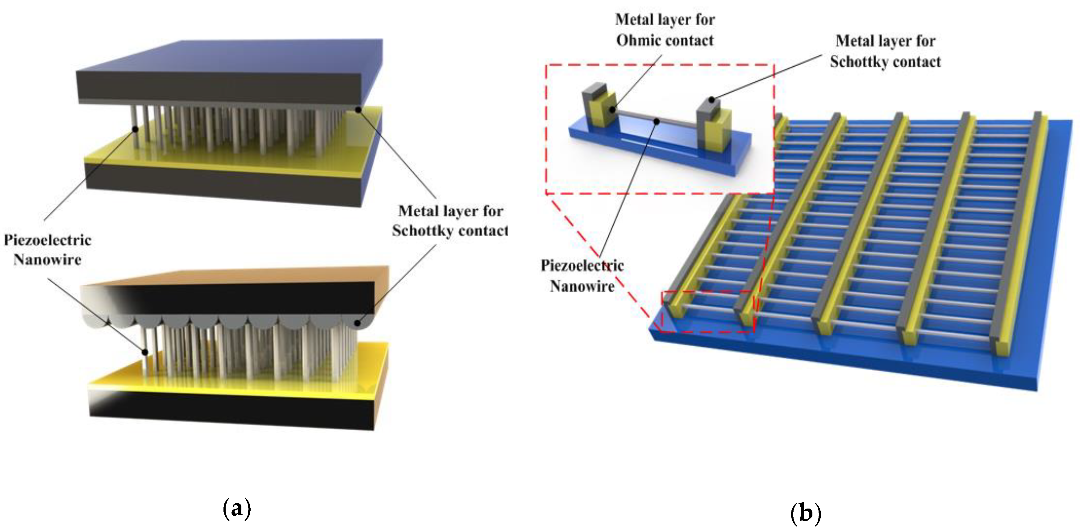
Figure 5. Geometrical configuration of piezoelectric nanogenerator (PENG). (a) Basic structure of vertically integrated nanogenerator. (b) The basic structure of laterally integrated nanogenerator.
3.1. Progress and Output Power Optimization in PENGs
The first was developed in the year 2006 based on ZnO nanowires [
8,
10,
11,
14]. The aligned nanowires were deflected by a conductive atomic microscope with platinum-coated silicon tip in contact mode. The energy output by one ZnO nanowire (NW) in one discharge event is 0.05 fJ, and the output voltage and power were ~8 mV and ~0.5 pW. For a nanowire density of 20/µm
2, the output power density is ~10 pW/µm
2 [
8]. The Schottky barrier formed between the microscope metal tip and the nanowires generates power with the power conversion efficiency of 17–30% [
8,
11,
21,
22]. Gao and Wang (2007) calculated the piezoelectric potential distribution of a nanowire of 50 nm diameter and 600 nm length as 0.3 V(appx) using perturbation theory [
14,
15]. The calculation showed that the piezoelectric potential on the surface of the nanowire is directly proportional to the lateral displacement of the nanowire and inversely proportional to the length-to-diameter aspect ratio of the nanowire [
15].
In 2007, Wang et al. [
23] developed a vertically aligned ZnO nanogenerator driven by an ultrasonic wave of frequency 41 kHz, which generated a unidirectional current of 0.15 nA with an open circuit voltage of 0.7 mV and output power volume density of 1–4 W/cm
3. This voltage is found to be less when compared to the one with an atomic microscope probe as the nanowires are less deflected by the ultrasonic waves. To effectively harvest the mechanical energy, Qin et al. designed a microfiber-based PENG in 2008 using a hydrothermal approach with a ZnO thin film layer as an electrode [
24]. This composite structure produces 1–3 mV output voltage and 4 nA current with a power density of 20–80 mW/cm
2.
Lin et al. (2008) demonstrated the cadmium sulfide (CdS)-based nanogenerator model similar to the ZnO nanowire-based nanogenerator [
25]. The nanowire was grown using hydrothermal and physical vapor deposition process. The nanowires produced by physical vapor deposition process seems to produce larger voltage when compared to the nanowires produced by the hydrothermal method. In 2008, Yang et al. fabricated a laterally integrated PENG using flexible substrate without sliding contacts, which are capable of producing alternating current. The fabricated PENG creates an oscillating output voltage (AC) up to ~50 mV when a single nanowire is stretched and released with a strain of 0.05–0.1%. Such type of flexible PENG can be connected in series inside a common substrate to raise the power output [
26]. The laterally integrated PENG is effective over vertically integrated PENG [
26]. Moreover, the output voltage is 15–100 times higher than direct-current [
23] and micro-fiber nanogenerators [
24]. Using the same flexible PENG concept later in 2010, Zhu et al. achieved an open circuit voltage of up to 2.03 V, a current of 107 nA, and a power density of ~11 mW/cm
3. The power generated from this PENG is stored in capacitors and used to light up a commercial light emitting diode (LED). Further, a peak output power density of ~0.44 mW/cm
2 and volume density of 1.1 W/cm
3 can be achieved by optimizing the density of the nanowires and by integrating 20 layers of nanowires. [
27]. Lin et al. (2008) used light to tune the output performance of the CdS-nanowires-based nanogenerators [
28]. The light reduces the height of the Schottky barrier on the nanowires, which gives a positive voltage output.
In 2010, Xu et al. successfully integrated 700 rows of ZnO nanowires to produce a peak voltage of 1.26 v and a maximum current of 28.8 nA at a low strain of 0.19% [
29]. Based on theoretical calculation, it is found that within the elastic linear mechanic’s regime, the piezoelectric potential of a nanowire is proportional to the amount of its deformation [
15]. So, in a vertical-nanowire-integrated nanogenerator, the nanowires are connected in parallel between two electrodes; as we increase the external strain, their deformation amount increases, growing consequently with the output voltage. The magnitude of the output voltage also depends upon the rate at which the external strain is applied [
29]. This high-power output can be used as a power source for neuroprosthetic devices; however, further research is necessary for effective integration.
Huang et al. (2010) successfully synthesized the first InN (Indium Nitride)-based nanogenerator. The InN nanowire is grown by vapor–liquid–solid (V-L-S) process with the use of an Au nanoparticle as a catalyst [
30]. The InN-based nanowire produces both positive and negative piezo-potential, and the maximum reaches up to 1 V, which is highest among all other nanowires. Nanogenerators based on lead zirconate titanate PZT nanofibres were demonstrated by Chen et al. (2010) [
31]. The PZT nanofibres were fabricated by the electro-spinning process, and fine platinum wire is used as an electrode, which was assembled on a silicon substrate. The peak voltage and power output were 1.63 V and 0.03 µW; the output voltage depends on the pressure applied to the nanogenerator device. Cha et al. (2011) enhanced the piezoelectric potential by using nanopore arrays of polyvinylidene fluoride (PVDF) and sonic driven [
32]; when the input sonic power of 100 dB at 100 Hz, the PENG generates an output of 2.6 V/0.6 µA, which is 5.2 times (piezoelectric potential)/ 6 times (piezoelectric current) higher than the PENG which uses bulk PVDF film, under the same sonic power input.
In piezoelectric materials, due to surface desorption and native defects, free charge carriers are formed [
22,
33]. Lu et al. (2012) found that these free charge carriers affect the piezoelectric potential known as the screening effect [
34]. ZnO nanorod was used for the study and they were illuminated using UV light; the carrier concentration increases up to 5.6 × 10
18 cm
−3 under 1.2 mW/cm
2 illumination. As the UV light intensity increases, carrier concentration also increases, which makes the current-voltage characteristics insensitive. The carrier concentration can be reduced by improving the intrinsic properties using surface passivation, thermal annealing, and oxygen plasma [
35,
36,
37,
38]. Pham et al. (2012) applied a simple thermal annealing treatment to the pristine ZnO nanorods in the presence of UV light and found the output piezoelectric potential was 25 times higher [
39].
Later in 2012, Zhu et al. demonstrated vertically integrated position-controlled piezoelectric ZnO nanowires that convert biomechanical energy into electrical energy with a high-level open-circuit voltage of 58 V, short circuit current of 134 µA, and a maximum power density of 0.78 W/cm
3 [
18].
Hu et al. (2012) improved the performance of the nanogenerators by using pretreatment methods like oxygen plasma, annealing air, and surface passivation with specific polymers on the grown ZnO nanowire films. The nanogenerator’s output voltage reached 20 V and the output current exceeded 6 µA [
35]. This nanogenerator successfully powered an automatic watch for more than 1 min (for 1000 cycles of deformation of nanogenerator).
Zhou et al. (2012), for the first time, demonstrated the energy-harvesting potential and piezotronic effect in vertically aligned CdSe nanowire arrays [
40]. Platinum is used as an electrode when a reasonable force or stress is applied on the nanowire with a maximum output voltage of 137 mV. The Schottky barrier between the platinum and the CdSe reduces the current.
Han et al. (2013) presented an innovative three-dimensional r-shaped hybrid NG design based on piezoelectric and triboelectric energy harvesting [
41]. The output performance of the device was enhanced by fabricating micro- or nanoscale devices on a polydimethylsiloxane (PDMS) surface, which was placed under an aluminum electrode on PVDF. The Al electrode was shared in common by both the piezoelectric and the triboelectric component. The piezoelectric and triboelectric generators exhibited an increased power density of 10.95 mW/cm
3 and 2.04 mW/cm
3, respectively. The hybrid r-shaped design showed relatively high reliability, as its performance was not degraded over 6000 continuous cycles under an external force with a frequency of 10 Hz.
Lithium-doped ZnO nanowires are used in large-scale nanogenerators for high performance [
38,
42]. Lu et al. (2015) [
43] utilized Au particles on the surface of the ZnO to reach an output voltage of 2 V and a current density of 1 µA/cm
2.
Ghosh and Mandal (2016) highlighted the intrinsic piezoelectric property in transparent fish scale, which is composed of self-assembled and ordered collagen nano-fibrils, and serves as a self-poled piezoelectric active component with a piezoelectric strength of −5.0 pC/N [
44]. A robust nanogenerator is fabricated by using gold electrodes of 90 nm thickness on both sides of the fish scale by sputtering followed by lamination with polypropylene film. This type of bio-piezoelectric nanogenerator under the repeated compressive stress of 0.17 MPa generates an output voltage of 4 V, short circuit current of 1.5 µA, and maximum output power density of 1.14 µW/cm
2. An enhanced output voltage of 14 V was obtained by serially integrating four of these bio-piezoelectric nanogenerators.
HaiBo et al. (2017) found that polymorphic phase sodium-potassium niobate (NKN) nanorods have the most significant piezoelectric strain constant (175 pm/V) as they have more directions for dipole rotation than the nanogenerators with rhombohedral or orthorhombic nanorods [
45]. Their experiment, using 0.7 g of PP (polymorphic phase) NKN nanorods, showed a maximum open-circuit voltage of 35 V and a short circuit current of 5.0 at a strain of 2.13% and an average strain rate of 3.7% s
−1. This nanogenerator generates a maximum power output of 16.5 µW for a load of 10 MΩ.
Chen et al. (2017) proposed a flexible piezoelectric nanogenerator based on a vertically aligned nanocomposite micropillar array of polyvinylidene fluoride-trifluoroethylene (P(VDF-TrFE))/barium titanate (BaTiO
3), which exhibits an enhanced voltage of 13.2 V and a current density of 0.33 µA/cm
2 [
46]. Upon the application of a force of 3 N at a frequency of 5 Hz, a flexible PENG based on barium titanate embedded polyvinylidene difluoride (i.e., BaTiO
3/PVDF) composite film exhibited a high output voltage of 14 V and short circuit current of 0.96 µA [
47].
Shi et al. (2018) fabricated a PENG by using electrospun nanocomposite fibre mats composed of 0.15 wt% graphene nanosheets and 15 wt% barium titanate nanoparticles, which generates a steady electric power of 11 V and 4.1 µW at a load frequency of 2 Hz and a strain of 4 mm even after 1800 cycles [
48]. The PENG also generates a peak voltage of 112 V during a finger pressing–releasing process, which is capable of powering 15 LEDs and a watch.
Jenkins et al. (2018) explored the behavior of diphenylalanine peptide using finite element analysis and found that this peptide nanowires can generate significantly higher power output than the nanowires made up of ZnO, lead zirconate titanate, and barium titanate [
49]. The nanogenerator made out of this nanowire achieved an open-circuit voltage up to −0.6 V and short circuit current up to 7 nA. The output voltage remains stable for more than 1000 cycles and the maximum power generated was 0.1 nW for a load resistance of 100 MΩ. Recently, in PVDF-based piezoelectric nanogenerators, the performance is increased by fabrication techniques, piezoelectric materials, conductive, and non-conductive fillers, which increases the piezoelectric crystal structures, alignment of dipoles, and charge transfer [
50]. The innovative 3D core multishell PENG showed improved performance [
51].
Kang et al. used GaN nanoporous layers instead of nanowires, using electrochemical etching process in their PENG [
52]. This suppresses the carrier screening effect and enhances the output voltage. Kang et al. (2017) demonstrated the transfer of a large area GaN membrane onto a flexible PET substrate in a transparent flexible piezoelectric nanogenerator using electrochemical lift-off process resulting in an output voltage and current of 4.2 v and 150 nA [
53]. The same electrochemical lift-off process was used by Johar et al. to fabricate a flexible PENG by forming a p-n NiO/GaN heterojunction [
54]. The lift-off process removes the residual stress in the GaN layer, which suppresses the free carrier screening. The developed PENG is capable of harnessing energy from the airflow, finger forces, and vibrations at a frequency of 20 Hz. Johar et al. (2018) fabricated the GaN (Gallium Nitride)-based piezoelectric nanogenerator using Ni as contact metal [
55]. The output performance was enhanced by using polydimethylsiloxane (PDMS) as a dielectric medium between GaN nanowire and Ni electrode. A maximum output voltage and current of 15 V and 85 nA were generated. The significant improvements in the development of PENG over the years are illustrated in .
Table 2. Significant improvements in the development of PENG.
| Year |
Author |
Materials |
Output Voltage & Short-Circuit Current |
Frequency/Strain |
Power Output |
Output Area Power Density |
Output Volume Power Density |
| 2006 |
Wang et al. [8] |
ZnO nanowires |
~6–9 mV |
~10 MHz |
0.5 pW/NW |
~1 nW/cm2 |
- |
| 2007 |
Wang et al. [23] |
ZnO nanowires |
−0.7 mV, 0.15 nA |
41 kHz |
~0.1 pW/NW |
10 µW/cm2 |
1–4 W/cm3 |
| 2008 |
Qin et al. [24] |
ZnO nanowires |
1–3 mV, 4 nA |
<10 Hz |
- |
20–80 mW/cm2 |
- |
| 2009 |
Yang et al. [26] |
ZnO nanowires/Kapton film |
~50 mV, 400–750 pA. |
22 cycles per minute |
- |
- |
|
| 2010 |
Zhu et al. [27] |
ZnO nanowires/PDMS film/Au film |
2.03 V, 107 nA, 200 pA (single nanowire) |
0.33 Hz, 0.1% strain, and strain rate of 5% s−1. |
- |
22 µW/cm2 (single layer)0.44 mW/cm2 (20 NW layers) |
~11 mW/cm3 (single layer)~1.1 W/cm3 (20 NW layers) |
| 2010 |
Xu et al. [29] |
ZnO nanowires |
1.26 V, 28.8 nA |
0.19% strain |
- |
- |
2.7 mW/cm3 |
| 2010 |
Huang et al. [30] |
InN nanowires |
1 V |
- |
- |
- |
- |
| 2010 |
Chen et al. [31] |
PZT nanofibres/platinum wires/PDMS |
1.63 V |
39.8 Hz |
0.03 µW |
|
|
| 2011 |
Cha et al. [32] |
PVDF nanowires |
2.6 V, 0.6 µA |
- |
- |
- |
0.17 mW/cm3 |
| 2012 |
Zhu et al. [18] |
ZnO nanowires/PMMA layer/ITO layer/Al |
58 V, 134 µA |
- |
- |
- |
0.78 W/cm3 |
| 2012 |
Hu et al. [35] |
ZnO nanowires/PMMA/Cr, Au electrodes |
20 V, 6 µA |
0.12% strain at strain rate of 3.56% s−1. |
- |
- |
0.2 W/cm3 |
| 2016 |
Ghosh and Mandal [44] |
Transparent fish scale |
4 V, 1.5 µA |
0.17 MPa |
- |
1.14 µW/cm2 |
- |
| 2016 |
Lu et al. [43] |
ZnO/PMMA/FTO, gold electrodes |
2 V |
- |
- |
- |
- |
| 2017 |
Cho et al. [42] |
Li-doped CuO2/ZnO |
- |
- |
~52.5 µW |
- |
- |
| 2017 |
Haibo et al. [45] |
NKN nanorods |
35 V, 5 µA |
2.13% strain at strain rate of 3.7% s−1. |
16.5 µW |
- |
- |
| 2017 |
Chen et al. [46] |
P(VDF-TrFE)/BaTiO3 |
13.2 V |
- |
- |
- |
- |
| 2017 |
Ku et al. [56] |
InN |
825 µV |
5 Hz |
- |
2.9 nW/cm2 |
- |
| 2017 |
Kang et al. [53] |
GaN/PET |
4.2 V, 150 nA |
Shear stress ~182 mN |
- |
- |
- |
| 2018 |
Dudem et al. [47] |
BaTiO3/PVDF, Ag/BTO |
14 V, 0.96 µA |
3 N, 5 Hz |
- |
~98.6 µW/cm2 |
- |
| 2018 |
Jenkins et al. [49] |
FF peptide nanowire |
−0.6 V, 7 nA |
10 nN force applied |
0.1 nW |
- |
- |
| 2018 |
Johar et al. [54] |
p-n NiO/GaN/PDMS/ITO/PET |
30 V, 1.43 µA |
20 Hz |
- |
- |
- |
| 2018 |
Johar et al. [55] |
GaN/Ni/PDMS |
15 V, 85 nA |
- |
- |
- |
- |
| 2018 |
Lee et al. [57] |
PZT-NH2 nanoparticels |
65 V, 1.6 µA |
- |
26 µW |
- |
- |
| 2019 |
Filippin et al. [51] |
ZnO nanowires |
170 mV |
- |
- |
- |
- |
| 2019 |
Maria et al. [58] |
Bi4Ti3O12, BiTO NPs/PDMS |
12.5 V, 100 nA |
- |
- |
562 µW/cm2 |
-
|
It is evident from that the condition of deformity, output power, and output power density was not always mentioned, which is essential to compare the performance among the PENGs. In all the studies, the authors have highlighted the output voltage obtained for the large surface, which is quite impressive to present the output results.
3.2. Applications of PENGs
PENGs acts as a sustainable power supply for various smart applications like self-powered nano/microsensors, self-powered electronics, wearable/flexible electronics, and biomedical applications [
2,
13,
14,
20,
22,
59,
60].
Hu et al. (2011) [
61] integrated the ZnO nanowire-based PENG onto a tire’s inner surface; the deformation of the tire during rotation gives a power output of 1.5 V and 25 nA with a maximum power density of 70 µW/cm
3. The PZT nanofibres have higher piezoelectric voltage constant and dielectric constant, making it ideal for nanogenerator and nanobattery applications [
31]. ZnO nanowire-based biosensors were developed in 2014, which paved the path for the future development of biosensing devices [
62]. PENGs effectively harvest energy from the motions of internal body parts and powers health monitoring devices and implantable devices like pacemakers, cardioverter-defibrillators, and neural stimulators [
63,
64,
65]. ZnO nanowires, indium tin oxide (ITO), and PZT film-based flexible and transparent nanogenerators were developed to harness power from finger typing [
66,
67,
68]. Piezoelectric nanogenerators that have excellent flexibility and high output voltage have promising applications in power electronics.
3.3. Outlook on PENGs
The PENGs have high output performance when compared to the other piezoelectric energy-harvesting techniques. The ZnO-based flexible nanogenerators were able to produce power output 11–22 times higher than the PZT-based bulk cantilever energy harvester [
27,
29]. The multifunctional piezoelectric nanogenerators are the exact source of power for wearable and implantable devices. As these nanogenerators are integrated with electronics, dresses, and human bodies, future development should be focused on flexibility, durability, and stability. Organic polymers with high flexibility have to be identified to replace the existing organic polymers. The research on semiconducting nanowires is crucial to further improve the performance and the applications of PENGs. The first PENG was based on ZnO nanowires, and there were several improved models with ZnO nanowires. Apart from these, various other 1D nanomaterials like CdS, GaN, ZnS, InN, CdSe, InAs and 2D MoS
2 that have good piezoelectric potential were also studied [
25,
30,
31,
53,
55,
82,
83]. Optimization of structural design, integration, and packing of nanogenerators for self-powered sensors are some of the future requirements that have to be addressed for efficient electromechanical energy conversion.