In a protonic ceramic fuel cell (PCFC), the cathode is a porous oxide material where electrochemical reduction takes place involving the reduction of oxygen and combination with protons from the electrolyte to form water. The cathode is generally recognised as critical for the performance of solid oxide fuel cells, and even more so for the proton-conducting class of ceramic devices. PCFCs are promising electrochemical devices for the efficient and clean conversion of hydrogen and low hydrocarbons into electrical energy. Their intermediate operation temperature (500–800 °C) proffers advantages in terms of greater component compatibility, unnecessity of expensive noble metals for the electrocatalyst, and no dilution of the fuel electrode due to water formation. Nevertheless, the lower operating temperature, in comparison to classic solid oxide fuel cells, places significant demands on the cathode as the reaction kinetics are slower than those related to fuel oxidation in the anode or ion migration in the electrolyte. Cathode design and composition are therefore of crucial importance for the cell performance at low temperature. The different approaches that have been adopted for cathode materials research can be broadly classified into the categories of protonic–electronic conductors, oxide-ionic–electronic conductors, triple-conducting oxides, and composite electrodes composed of oxides from two of the other categories.
- proton ceramic fuel cell
- cathode
- oxygen electrode
- triple-conducting oxides
- protonic-electronic conductor
1. Background
[1]
Table 1) based on oxide-ion conducting electrolytes have been intensely developed due to their high combined heat and power efficiency, long-term stability, low emissions, and relatively low cost [2][3]. The high operating temperature (typically in the range 800–1000 °C) provides the advantage of fuel flexibility, and their operation with simple hydrocarbons is often touted as a gateway to their widespread employment with hydrogen as fuel. Nevertheless, the high operating temperature is associated with long start-up times and problems with mechanical and chemical compatibility.
Table 1. General abbreviations.
| Basic Concept | Abbreviation | Basic Concept | Abbreviation |
|---|---|---|---|
| Area Specific Resistance | ASR | Protonic Ceramic Fuel Cells | PCFCs |
| Distribution of Relaxation Times | DRT | Ruddlesden–Popper | RP |
| Electrode Polarization Resistance | Rp | Secondary Ion Mass Spectroscopy | SIMS |
| Electrochemical Impedance Spectroscopy | EIS | Solid Oxide Fuel Cells | SOFCs |
| Maximum Power Density | MPD | Thermogravimetric Analysis | TGA |
| Mixed Oxide-Ion Electron Conductors | MIECs | Triple Phase Boundary | TPB |
| Oxygen Reduction Reaction | ORR | Triple Protonic Oxide-Ionic Electron Hole Conducting Oxides | TCOs |
| Protonic Ceramic Electrolysis Cells | PCECs |
Ceramic fuel cells with a proton-conducting electrolyte (protonic ceramic fuel cells, PCFCs, or proton-conducting solid oxide fuel cells, H
+-SOFCs) have been of ever-growing interest since the pioneering work of Iwahara starting in the 1980s on proton-conducting ceramic materials [4][5][6][7]. Such cells may also be operated in reverse to affect the electrolysis of water (protonic ceramic electrolysis cells, PCECs) [8][9]. These electrochemical cells may operate within an intermediate temperature (400–800 °C), which is partly due to the higher mobility and lower activation energy of protons in comparison to oxide ions in this range. PCFCs have additional advantages: the water in the electrochemical reaction is generated in the cathode, so no further fuel recycling is required, and Ni in the fuel electrode remains at a suitably low oxygen partial pressure [10]. However, lowering the operating temperature creates much larger overpotentials at the electrode–electrolyte interface [11]. Specifically, the reaction kinetics related to oxygen reduction occurring in the air electrode are slower than fuel oxidation in the anode or ion migration in the electrolyte [12]. Hence, the cathode plays a major role in determining the efficiency of fuel-cell operation in the intermediate-temperature range. Electrochemical modelling has shown that, whereas lower ohmic resistance offered by thinner electrolytes is the easiest way to improve the performance of PCFCs, the performance is otherwise restricted by the attempted current density at the cathode, meaning that the cathode limits the performance of the whole cell [12].
2. Theory
A number of studies of protonic ceramic single cells, particularly earlier studies, employed a single metallic phase as an air electrode, most commonly platinum [10][13][14]. The elementary reaction steps occurring in a Pt cathode in contact with a protonic ceramic membrane in fuel-cell mode for the overall oxidation reaction have been described by Uchida et al. [15] as follows:
Analogous to the oxide-ionic conducting SOFCs, the cathodic, multistep reaction encompassed in Equations (2)–(7) may be considered as the “electrode surface path” [16]. It includes the diffusion of oxygen from the gas phase to adsorption (ad) on the electrode surface (2), oxygen dissociation at the surface (3), and diffusion to the triple phase boundary (TPB) (4), where protonic species from the electrolyte combine with the dissociated and reduced oxygen (5) to produce water (6), which is finally evaporated to the gas phase (7).
- (i) Improving the electronic conductivity in proton-conducting oxides via substitution of mixed-valence cations (Figure 1a).
-
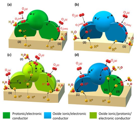 Figure 1.Electrochemical reaction steps corresponding to the cathodic reduction reaction occurring through: (a) the “electrode-surface path” (1) and “bulk-electrode path for protons” (2) for a mixed protonic–electronic conductor; (b) the “electrode-surface path” (1) and “bulk-electrode path for oxide ions” (2) for a mixed oxide-ionic–electronic conducting electrode; (c) the “electrode-surface path” (1), “bulk-electrode path for protons”, (2) and “bulk-electrode path for oxide ions” (3) for a triple protonic–oxide-ionic–electronic conducting oxide; (d) “bulk-electrode path for oxide ions” (1), “bulk-electrode path for protons” (2) and (3), for a composite based on an oxide ionic–electronic conductor and a mixed protonic–electronic conductor.
 - (ii) Incorporation of a mixed oxide-ion–electronic conductor (MIEC) analogous to the classical oxide-ion conducting SOFC cathode (Figure 1b).
- (iii) Employing so-called triple-conducting oxides (TCOs) with proton, oxide-ion, and electron conductivity (Figure 1c).
- (iv) Designing composite electrodes with a proton-conducting oxide (including improving electron conductivity via strategy (i) and an oxide-ion and electron-conducting component (Figure 1d).
The importance of the cathode in the development of PCFCs has only been given more prominence in the past few years. Nevertheless, considerable progress has been achieved in this time. Developments and an overview of the current state-of-the-art in the field of cathodes for protonic ceramic fuel cells can be found in the review "Perspectives on Cathodes for Protonic Ceramic Fuel Cells", Applied Sciences 2021, 11, 5363.
References
- Minh, N.Q. Ceramic Fuel Cells. J. Am. Ceram. Soc. 1993, 76, 563–588.Winter, C.-J. Hydrogen energy—Abundant, efficient, clean: A debate over the energy-system-of-change. Int. J. Hydrog. En-ergy 2009, 34, S1–S52, doi:10.1016/j.ijhydene.2009.05.063.
- Ormerod, R.M. Solid oxide fuel cells. Chem. Soc. Rev. 2003, 32, 17–28.Minh, N.Q. Ceramic Fuel Cells. J. Am. Ceram. Soc. 1993, 76, 563–588, doi:10.1111/j.1151-2916.1993.tb03645.x.
- Brett, D.J.L.; Atkinson, A.; Brandon, N.P.; Skinner, S.J. Intermediate temperature solid oxide fuel cells. Chem. Soc. Rev. 2008, 37, 1568–1578.Ormerod, R.M. Solid oxide fuel cells. Chem. Soc. Rev. 2003, 32, 17–28, doi:10.1039/B105764M.
- Coors, W.G. Protonic ceramic fuel cells for high-efficiency operation with methane. J. Power Sources 2003, 118, 150–156.Brett, D.J.L.; Atkinson, A.; Brandon, N.P.; Skinner, S.J. Intermediate temperature solid oxide fuel cells. Chem. Soc. Rev. 2008, 37, 1568–1578, doi:10.1039/b612060c.
- Iwahara, H.; Esaka, T.; Uchida, H.; Maeda, N. Proton conduction in sintered oxides and its application to steam electrolysis for hydrogen production. Solid State Ion. 1981, 3–4, 359–363.Coors, W.G. Protonic ceramic fuel cells for high-efficiency operation with methane. J. Power Sources 2003, 118, 150–156, doi:10.1016/S0378-7753(03)00072-7.
- Iwahara, H. Technological challenges in the application of proton conducting ceramics. Solid State Ion. 1995, 77, 289–298.Iwahara, H.; Esaka, T.; Uchida, H.; Maeda, N. Proton conduction in sintered oxides and its application to steam electrolysis for hydrogen production. Solid State Ion. 1981, 3–4, 359–363, doi:10.1016/0167-2738(81)90113-2.
- Duan, C.; Huang, J.; Sullivan, N.; O’Hayre, R. Proton-conducting oxides for energy conversion and storage. Appl. Phys. Rev. 2020, 7, 011314.Iwahara, H. Technological challenges in the application of proton conducting ceramics. Solid State Ion. 1995, 77, 289–298, doi:10.1016/0167-2738(95)00051-7.
- Duan, C.; Kee, R.; Zhu, H.; Sullivan, N.; Zhu, L.; Bian, L.; Jennings, D.; O’Hayre, R. Highly efficient reversible protonic ceramic electrochemical cells for power generation and fuel production. Nat. Energy 2019, 4, 230–240.Duan, C.; Huang, J.; Sullivan, N.; O’Hayre, R. Proton-conducting oxides for energy conversion and storage. Appl. Phys. Rev. 2020, 7, 011314, doi:10.1063/1.5135319.
- Medvedev, D. Trends in research and development of protonic ceramic electrolysis cells. Int. J. Hydrog. Energy 2019, 44, 26711–26740.Duan, C.; Kee, R.; Zhu, H.; Sullivan, N.; Zhu, L.; Bian, L.; Jennings, D.; O’Hayre, R. Highly efficient reversible protonic ce-ramic electrochemical cells for power generation and fuel production. Nat. Energy 2019, 4, 230–240, doi:10.1038/s41560-019-0333-2.
- Lei, L.; Zhang, J.; Yuan, Z.; Liu, J.; Ni, M.; Chen, F. Progress Report on Proton Conducting Solid Oxide Electrolysis Cells. Adv. Funct. Mater. 2019, 29.Medvedev, D. Trends in research and development of protonic ceramic electrolysis cells. Int. J. Hydrog. Energy 2019, 44, 26711–26740, doi:10.1016/j.ijhydene.2019.08.130.
- Ni, M.; Leung, M.K.H.; Leung, D.Y.C. Theoretical analysis of reversible solid oxide fuel cell based on proton-conducting electrolyte. J. Power Sources 2008, 177, 369–375.Lei, L.; Zhang, J.; Yuan, Z.; Liu, J.; Ni, M.; Chen, F. Progress Report on Proton Conducting Solid Oxide Electrolysis Cells. Adv. Funct. Mater. 2019, 29, doi:10.1002/adfm.201903805.
- Tsai, C.-L.; Schmidt, V.H. Fabrication, Performance, and Model for Proton Conductive Solid Oxide Fuel Cell. J. Electrochem. Soc. 2011, 158, B885.Ni, M.; Leung, M.K.H.; Leung, D.Y.C. Theoretical analysis of reversible solid oxide fuel cell based on proton-conducting electrolyte. J. Power Sources 2008, 177, 369–375, doi:10.1016/j.jpowsour.2007.11.057.
- Asano, K.; Hibino, T.; Iwahara, H. A Novel Solid Oxide Fuel Cell System Using the Partial Oxidation of Methane. J. Electrochem. Soc. 1995, 142, 3241–3245.Tsai, C.-L.; Schmidt, V.H. Fabrication, Performance, and Model for Proton Conductive Solid Oxide Fuel Cell. J. Electrochem. Soc. 2011, 158, B885, doi:10.1149/1.3596361.
- Luisetto, I.; Di Bartolomeo, E.; D’Epifanio, A.; Licoccia, S. CO2∕CH4 Reforming High Temperature Proton Conductor (HTPC) Fuel Cells. J. Electrochem. Soc. 2011, 158, B1368.Asano, K.; Hibino, T.; Iwahara, H. A Novel Solid Oxide Fuel Cell System Using the Partial Oxidation of Methane. J. Electro-chem. Soc. 1995, 142, 3241–3245, doi:10.1149/1.2049968.
- Uchida, H.; Tanaka, S.; Iwahara, H. Polarization at Pt electrodes of a fuel cell with a high temperature-type proton conductive solid electrolyte. J. Appl. Electrochem. 1985, 15, 93–97.Luisetto, I.; Di Bartolomeo, E.; D’Epifanio, A.; Licoccia, S. CO2∕CH4 Reforming High Temperature Proton Conductor (HTPC) Fuel Cells. J. Electrochem. Soc. 2011, 158, B1368, doi:10.1149/2.042111jes.
- Fleig, J. Solid Oxide Fuel Cell Cathodes: Polarization Mechanisms and Modeling of the Electrochemical Performance. Annu. Rev. Mater. Res. 2003, 33, 361–382.Uchida, H.; Tanaka, S.; Iwahara, H. Polarization at Pt electrodes of a fuel cell with a high temperature-type proton conduc-tive solid electrolyte. J. Appl. Electrochem. 1985, 15, 93–97, doi:10.1007/BF00617745.
- Zhu, H.; Kee, R.J. Modeling Protonic-Ceramic Fuel Cells with Porous Composite Electrodes in a Button-Cell Configuration. J. Electrochem. Soc. 2017, 164, F1400–F1411.Fleig, J. Solid Oxide Fuel Cell Cathodes: Polarization Mechanisms and Modeling of the Electrochemical Performance. Annu. Rev. Mater. Res. 2003, 33, 361–382, doi:10.1146/annurev.matsci.33.022802.093258.
- Zhu, H.; Kee, R.J. Modeling Protonic-Ceramic Fuel Cells with Porous Composite Electrodes in a Button-Cell Configuration. J. Electrochem. Soc. 2017, 164, F1400–F1411, doi:10.1149/2.0591713jes.