Your browser does not fully support modern features. Please upgrade for a smoother experience.
Please note this is a comparison between Version 1 by Zijian Liu and Version 2 by Vicky Zhou.
The rotor eccentricity is idealized as static eccentricity (SE), dynamic eccentricity (DE), or mixed eccentricity (ME), as shown in. The SE indicates that the rotor and the stator centers do not coincide, and the rotor revolves the rotor center. The DE indicates that the rotor and the stator centers do not coincide, and the rotor revolves both the stator and the rotor centers.
- fault diagnosis
- rotor
- eccentricity
- electric machine
1. Introduction
The diagnostic approaches toward predictive maintenance for rotating electric machines have been developed for decades. They provide early detection and severity evaluation with ease, saving time and labor costs [1][2][3]. A good diagnostic approach should also provide out-of-service margin, which helps to make full use of service life and make maintenance schedules.
In this area, the diagnosis for rotor eccentricity has attracted attention due to its catastrophic consequences. In general, there is a tolerable inherent eccentricity degree due to limited accuracy of fabrication and assembly. The permissible eccentricity could be exacerbated due to stresses or faults, such as misalignment and bearing wear. A lateral injure of bearing ball could cause shaft incline and rotor eccentricity occurs. Longtime misalignment would cause shaft bent and rotor eccentricity occurs. The aggravated eccentricity causes unbalanced magnetic pull, increased cogging torque, excessive vibration, and rotor temperature increase [4]. As the direction of unbalanced magnetic pull is roughly consistent with the direction of eccentricity, the rotor is gradually dragged to a more eccentric position. This positive feedback eventually evolves to a rotor stator rub, which harms lamination and generates sparks. Besides, an inverter-driven permanent magnet synchronous machine (PMSM) prototype with severe eccentricity could cause serious torque oscillations and inverter failures. Nonetheless, these hazards can be avoided by applying advanced diagnostic approaches [5].
Various diagnostic methods have emerged so far, and there are reviews regarding the diagnosis of eccentricity [6][7][8][9]. These articles discuss either one type of rotary machines or eccentricity. On the other hand, other reviews on general topics of diagnostics cannot give full discussion on eccentricities. While in this paper, all the possible modeling and diagnostic approaches for rotor eccentricities in general types of electric machines are reviewed. It is held that there are common research routes in the eccentricity modeling and diagnostics for any type of machines. Therefore, the paper is organized in a general frame and the most representative diagnostic strategies are reviewed. Suggestions for future research from the perspective of electrical engineering are given.
2. Facts about Rotor Eccentricity
In the literature, the rotor eccentricity is idealized as static eccentricity (SE), dynamic eccentricity (DE), or mixed eccentricity (ME), as shown in Figure 1 [10][11]. The SE indicates that the rotor and the stator centers do not coincide, and the rotor revolves the rotor center. The DE indicates that the rotor and the stator centers do not coincide, and the rotor revolves both the stator and the rotor centers. The ME contains both the SE and the DE, and in which case the rotor revolves a third center other than the stator and the rotor centers. The definitions of SE degree ρs, DE degree ρd, and ME degree ρm are depicted in Figure 2, where g0 represents the air-gap length. It is indicated that if ρs equals ρd, then the rotor center trajectory will pass through the stator center. In [12], an axial inclined or a bent rotor is modeled in segments to analyze the air-gap flux and unbalanced magnetic pull. Nonetheless, the 2-D SE, DE, and ME models are enough for study.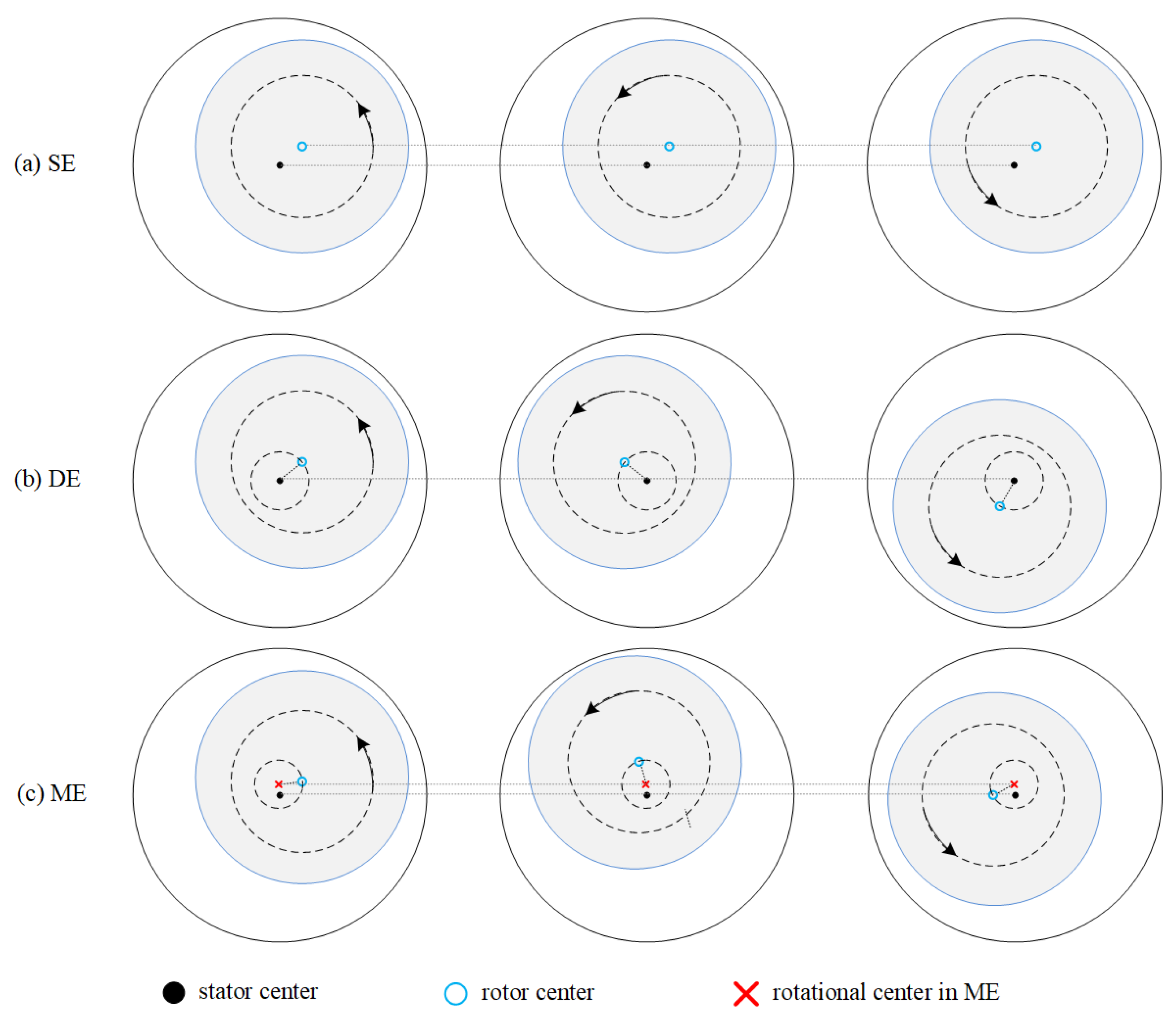 Figure 1. Diagram of RE. (a) SE. (b) DE. (c) ME.
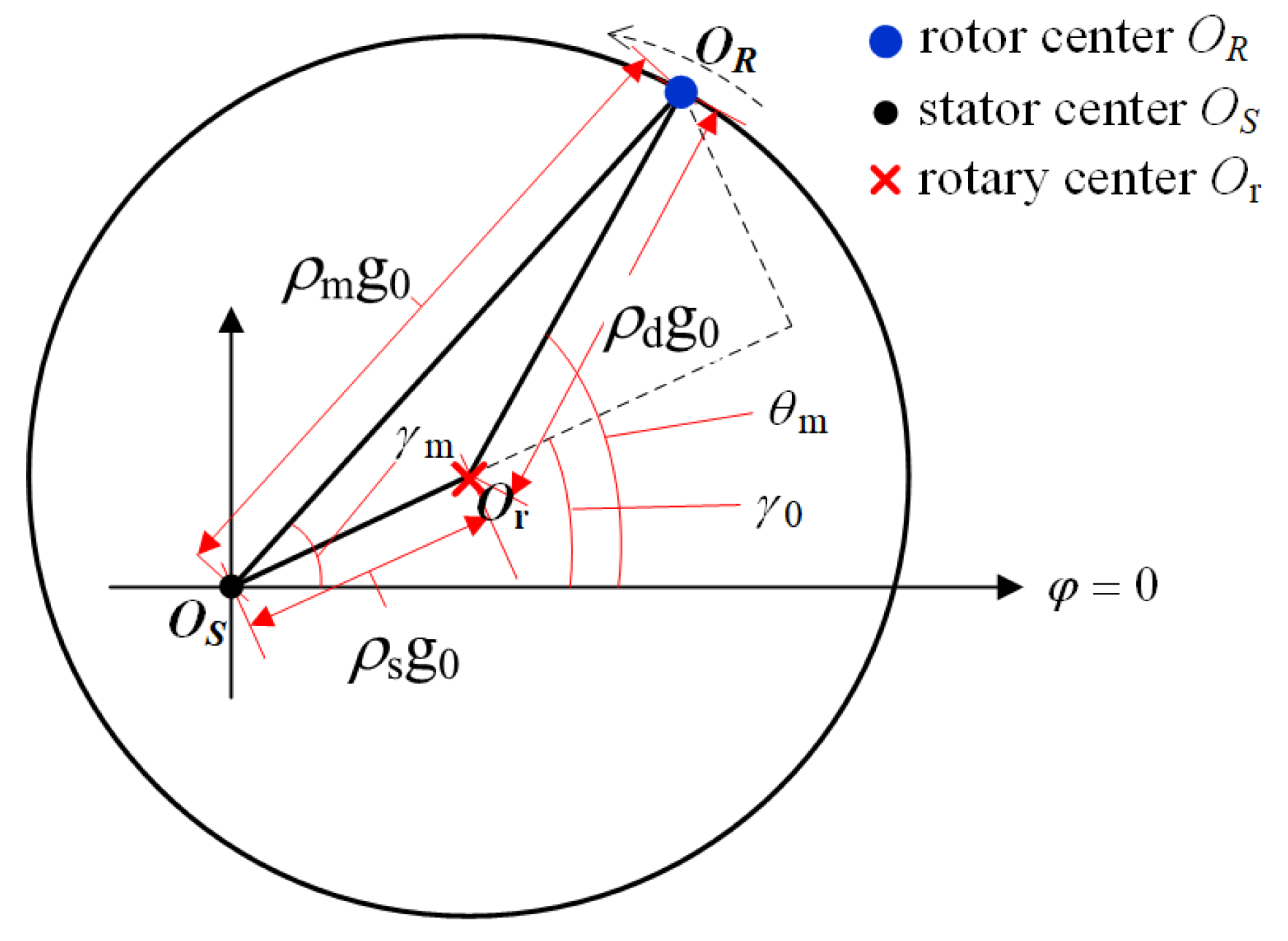 Figure 2. Calculation of ME.
37. Future ProspectsDiscussion on Continued Research
The model-based, signal-based, and data-based eccentricity diagnostic approaches are suitable for applications with diverse properties and demands. The signal-based approaches are mostly proposed for startup process or feature extraction before data processing. The data-based approaches are basically studied for multiple faults classification in steady-state process. The model-based approaches have developed into all kinds of means and are also suitable for steady-state diagnosis. Moreover, the model-based approaches have clear theoretical basis for faults separation. These approaches could be used in combination in practice, such as in [15]. Comparison of predominant methods in distinguishing eccentricity and demagnetization is presented in Table 13.Table 13.
Comparison of predominant methods in distinguishing eccentricity and demagnetization.
| Auxiliary Voltage Injection | Sensor-Based Detection |
Coordinate Transform |
|---|
| Principle | Inductances (or impedances) are modulated and distorted | Magnetic field distortion | Variation of components transform | |||||||
| Real-time capability | Offline | [16] | or real-time online | [17] | Real-time online | [18] | Real-time | [19][20] | or non-real-time online | [15] |
| Pros | Small computation and low cost No additional hardware or FFT is required No winding structure modification is required |
Simple principle and no interference Robust to operating conditions |
No interference | |||||||
| Cons | The diagnostic condition is restricted to low speed or offload The operation is intermittently affected |
Additional fabrication cost, and reliability issue |
Additional computation | [15] | , hardware or fabrication cost | [19][20] | , and reliability issue |
The ME, PD, and load torque oscillation could be separated by observing the stator inductances if a proper time-varying model observer was designed. The principle is shown in Figure 39, which presents the distortion of one stator phase inductance under ME and PD. The amplitude of stator inductance under ME is modulated by frequency fr, which is notably different from PD fault. In addition, the load torque oscillation hardly affects motor inductances. Then the observer-based approach could be effective.
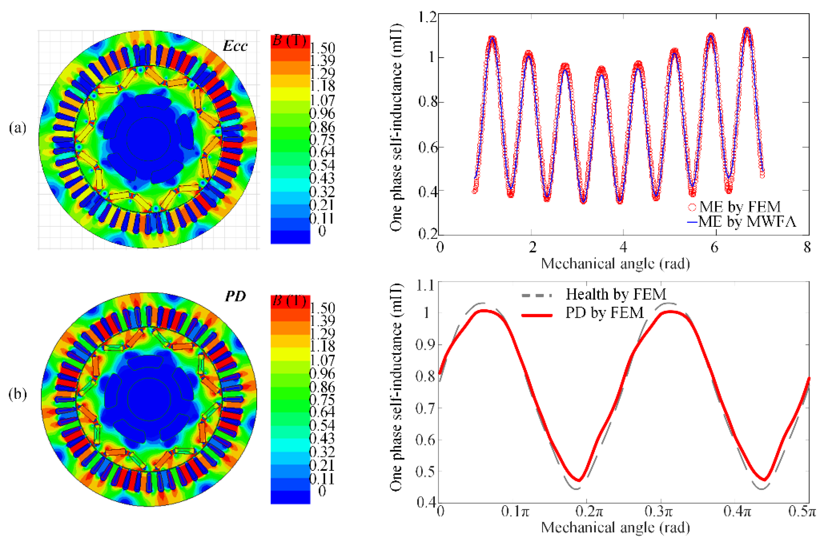 Figure 39. Variation in stator inductances due to (a) ME and (b) PD.
In conclusion, in terms of modeling approaches, the MEC and MWFA are suitable for the early verification of diagnostic strategies, while the analytical methods are suitable for the electromagnetic analysis. The FEM is an effective verification tool for both modeling and diagnostic methods. The choice of modeling approaches depends on the specific selection of model-based approaches. In terms of diagnostic approaches, a reliable diagnosis requires accurate discrimination of ME, PD, and load torque oscillations, which have similar fault characteristics in the collected signals. The existing technologies have achieved real-time online visualized diagnosis and fault separation. The search coil-based diagnosis has the highest robustness while the injection-based diagnosis has the least practice cost. However, their shortcomings restrict the scope of application. The ideal solution is to develop a reliable low-cost noninvasive visualized online diagnostic without interfering with the normal operation. The observer-based diagnostic approach for eccentricity is suggested as the ongoing research interest.
References
- Antonino-Daviu, J.A.; Quijano-Lopez, A.; Rubbiolo, M.; Climente-Alarcon, V. Advanced analysis of motor currents for the diagnosis of the rotor condition in electric motors operating in mining facilities. IEEE Trans. Ind. Appl. 2018, 54, 3934–3942.
- Choi, S.; Haque, M.S.; Tarek, M.T.B.; Mulpuri, V.; Duan, Y.; Das, S.; Garg, V.; Ionel, D.M.; Masrur, M.A.; Mirafzal, B.; et al. Fault diagnosis techniques for permanent magnet ac machine and drives—A review of current state of the art. IEEE Trans. Transp. Electrif. 2018, 4, 444–463.
- Henao, H.; Capolino, G.A.; Fernandez-Cabanas, M.; Filippetti, F.; Bruzzese, C.; Strangas, E.; Pusca, R.; Estima, J.; Riera-Guasp, M.; Hedayati-Kia, S. Trends in fault diagnosis for electrical machines: A review of diagnostic techniques. IEEE Ind. Electron. Mag. 2014, 8, 31–42.
- Artigao, E.; Honrubia-Escribano, A.; Gómez-Lázaro, E. In-service wind turbine DFIG diagnosis using current signature analysis. IEEE Trans. Ind. Electron. 2020, 67, 2262–2271.
- Faiz, J.; Nejadi-Koti, H. Eccentricity fault diagnosis indices for permanent magnet machines: State-of-the-art. IET Electr. Power Appl. 2019, 13, 1241–1254.
- Faiz, J.; Ojaghi, M. Different indexes for eccentricity faults diagnosis in three-phase squirrel-cage induction motors: A review. Mechatronics 2009, 19, 2–13.
- Faiz, J.; Moosavi, S. Eccentricity fault detection—From induction machines to DFIG—A review. Renew. Sustain. Energy Rev. 2016, 55, 169–179.
- Salah, A.A.; Dorrell, D.G.; Guo, Y. A Review of the Monitoring and Damping Unbalanced Magnetic Pull in Induction Machines Due to Rotor Eccentricity. IEEE Trans. Ind. Appl. 2019, 55, 2569–2580.
- Aggarwal, A.; Strangas, E.G. Review of Detection Methods of Static Eccentricity for Interior Permanent Magnet Synchronous Machine. Energies 2019, 12, 4105.
- Riera-Guasp, M.; Antonino-Daviu, J.A.; Capolino, G.A. Advances in electrical machine, power electronic, and drive condition monitoring and fault detection: State of the art. IEEE Trans. Ind. Electron. 2014, 62, 1746–1759.
- Faiz, J.; Ghods, M.; Tajdyni, A. Dynamic air gap asymmetry fault detection in single-sided linear induction motors. IET Electr. Power Appl. 2019, 14, 605–613.
- Di, C.; Bao, X.; Wang, H.; Lv, Q.; He, Y. Modeling and analysis of unbalanced magnetic pull in cage induction motors with curved dynamic eccentricity. IEEE Trans. Magn. 2015, 51, 1–7.
- Nandi, S.; Toliyat, H.A.; Li, X. Condition monitoring and fault diagnosis of electrical motors—A review. IEEE Trans. Energy Convers. 2005, 20, 719–729.
- Nandi, S.; Ahmed, S.; Toliyat, H.A. Detection of rotor slot and other eccentricity related harmonics in a three phase induction motor with different rotor cages. IEEE Trans. Energy Convers. 2001, 16, 253–260.
- Haddad, R.Z.; Lopez, C.A.; Foster, S.N.; Strangas, E.G. A voltage-based approach for fault detection and separation in permanent magnet synchronous machines. IEEE Trans. Ind. Appl. 2017, 53, 5305–5314.
- Hong, J.; Park, S.; Hyun, D.; Kang, T.J.; Lee, S.B.; Kral, C.; Haumer, A. Detection and classification of rotor demagnetization and eccentricity faults for PM synchronous motors. IEEE Trans. Ind. Appl. 2012, 48, 923–932.
- Liu, Z.; Huang, J.; He, S. Diagnosis of air-gap eccentricity and partial demagnetisation of an interior permanent magnet synchronous motor based on inverse transient complex inductance vector theory. IET Electr. Power Appl. 2018, 12, 1166–1175.
- Da, Y.; Shi, X.; Krishnamurthy, M. A new approach to fault diagnostics for permanent magnet synchronous machines using electromagnetic signature analysis. IEEE Trans. Power Electron. 2013, 28, 4104–4112.
- Bruzzese, C. Diagnosis of eccentric rotor in synchronous machines by analysis of split-phase currents—Part I: Theoretical analysis. IEEE Trans. Ind. Electron. 2014, 61, 4193–4205.
- Bruzzese, C. Diagnosis of eccentric rotor in synchronous machines by analysis of split-phase currents—Part II: Experimental analysis. IEEE Trans. Ind. Electron. 2014, 61, 4206–4216.
More