1. Introduction
Fiber interferometric sensors have basically the same operating principle as traditional optical interferometers. By replacing traditional discrete optical components with fiber devices, a fiber interferometer can achieve many benefits, including easy alignment, low insert loss, convenient arrangement, high stability, high coupling efficiency, etc. In fiber interferometer systems, the light travels along different optical paths and combines again at the output side, which generates an interference spectrum. External perturbations that are applied to the interference arms may cause property variations of the interferometer, including fiber length, effective refractive index, mode loss, etc., eventually leading to a change in optical path difference (OPD) or optical intensity. The change in OPD and intensity can be precisely retrieved by measuring the far-field interferogram [
11,
12], the wavelength shift of the interference spectrum [
13,
14], the light intensity [
15,
16], the fast Fourier transform (FFT) of light power’s time response [
17,
18], etc.
Apparently, compactness, stability, simplicity, and robustness play a decisive role in the performance and applicability of optical fiber sensing systems, and these aspects can be improved by using multicore fibers instead of single-core fibers to construct fiber interferometers. Benefiting from containing multiple individual cores in one fiber, MCFs can support the multiple cavities of the FPI, the multiple interference arms of the MI and MZI, and several supermodes in one fiber cladding, which can greatly simplify the structures of sensors and enhance the robustness and compactness of the sensing systems. On the other hand, since the side cores are usually more sensitive to external disturbances, MCF interferometric sensors have intrinsic advantages in sensing applications that are related to bending and strain, e.g., curvature [
13,
19], vibration [
18,
20], twisting angle [
7,
21], fluid flow [
19,
22], etc. Particularly, MCF interferometric sensors are able to distinguish the direction of bending [
15,
23], which has enabled many new sensing applications, e.g., 3D shapes [
24]. In addition, MCF interferometric sensors have also been used to measure other external environmental parameters, e.g., temperature [
25,
26], gas concentration [
27], refractive index [
28,
29], and so on.
The following sections will summarize different MCF interferometric sensor structures that are commonly used in fiber optic sensing, including their configurations, operating principles, and representative studies, as well as the benefits brought by MCFs.
2. MCF-Based Fabry–Perot Interferometric Sensors
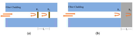
As shown in Figure 1, Fabry–Perot interferometers (FPIs) can be classified into intrinsic FPIs and extrinsic FPIs according to the formation of the interference cavity. In the intrinsic FPI, the interference cavity is fabricated inside the optical fiber, while in the extrinsic FPI, a microcavity is fabricated between the cleaved optical fiber end and another external reflection surface. In comparison, the intrinsic FPI is generally more robust but requires more high-cost fabrication methods, such as femtosecond laser processing, chemical etching, external fixation using capillaries, etc.
Figure 1. Schematic diagram of (a) an intrinsic FPI and (b) an extrinsic FPI.
In the FPI, the reflective optical interference intensity can be expressed as
where
I1 and
I2 are the intensities of the reflective light from two interfaces, and
φ is the phase difference between the two reflective lights, which can be defined as
where
λ is the wavelength of the light source,
L is the length of the cavity, and
n is the refractive index of the medium in the cavity. The free spectrum range (FSR) at wavelength
λ is given by
One can see from Equation (3) that bending/strain-induced cavity length L variation and environmental-perturbations-induced refractive index n changes will lead to a shift in the optical interference spectrum, which can be used to retrieve the perturbation of the parameters.
In MCF-based Fabry–Perot interferometric sensors, FPIs are usually discrete and parallel in different cores of a weakly coupled MCF [
13,
14,
30,
31,
32,
33]. Instead of using a single FPI, it is able to achieve vector sensing by measuring several parallel FPIs simultaneously in a single MCF, such as bending direction [
13,
30], torsion [
31], flow direction [
32], etc.
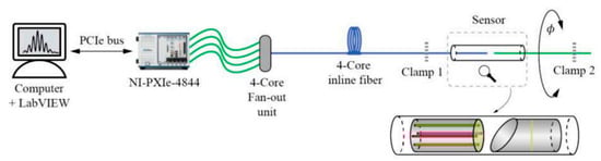
In addition to bending sensing, parallel FPIs can also be used to measure tiny torsion angles by utilizing the twist-induced cavity length variation. For example, in 2022, Jing Zhang et al. proposed a torsion sensor where four FPIs were made up of vertically cleaved four-core fibers and an angled mirror, and the sensor was demonstrated to be capable of sensing torsion with a range of ±90° and a resolution of 0.01° [
31]. As shown in
Figure 2, the cavity length of each FPI will change, respectively, when torsion is applied to the four-core fiber and the spectral characteristics of each FPI can be analyzed utilizing a four-core fan-out unit.
Figure 2. Schematic of the torsion sensor based on FPIs made up of a 4-core fiber [
31].
Furthermore, in addition to bending and torsion sensing, MCF Fabry–Perot interferometer (MFPI)-based sensors can also be used for axial displacement sensing by changing the distance between the two reflective surfaces of FPIs. By fabricating reference and sensing FPIs in a single MCF, a compact sensor head can be achieved. In general, due to the compact reflective structure, heat resistance, corrosion resistance, and high electromagnetic immunity, MFPI-based sensors can be easily deployed in complex actual environments for a variety of sensing applications.
3. MCF-Based Michelson Interferometric Sensors
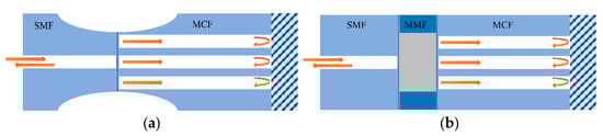
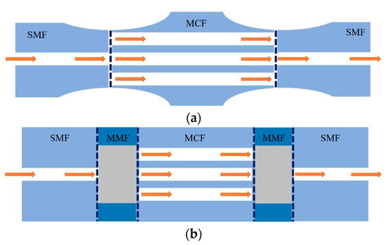
Thanks to the multicore structure of MCF, it provides an excellent platform to construct an in-fiber integrated Michelson interferometer by coupling light into different cores so that the cores act as the arms of the Michelson interferometer. Fresnel reflection light is generated on the end face of the cleaved optical fiber, and the reflected light from different cores of the MCF will give rise to interference. Typical coupling methods of MCF-based Michelson interferometers (MMI) are shown in
Figure 3. Instead of using fiber couplers, in order to couple light into different cores of an MCF, the widely used approaches including tapering the fiber at the fusion splice region [
10,
19,
22,
35,
36] or inserting a segment of multimode fiber (MMF) between the single-mode fiber (SMF) and MCFs [
6]. These coupling methods have the advantages of compact structure and long-term stability because of the good spatial consistency of the interference arms. Note that by enhancing the coupling efficiency between fiber cores, e.g., the center core and side cores of the MCF, the light power in each interference arm can be more even and the fringe visibility of the interference spectrum can be improved, which is instrumental in the simplicity of demodulation and the accuracy of measurement.
Figure 3. Schematics of typical coupling methods of the MCF-based Michelson interferometer. (a) Tapering the MCFs at the fusing point, (b) fusing a segment of MMF between the SMF and MCFs.
In addition to the method of tapering, to optimize the interference spectrum quality of the MMI, coupling configurations based on a fiber ball structure have been demonstrated, which have been fabricated on the fusion surface [
37] and the reflecting surface [
25]. In 2016, Li Duan et al. demonstrated an MMI temperature sensor by tapering the fusion-spliced region between the SMF and the MCF and fabricating a spherical end face by arc-fusion splicing. The first coupling appears when the light transmits through the tapered region and the second coupling occurs at the spherical end face when the light is reflected. The light power of the side cores and the center core can be balanced at the spherical end face and, as a result, a high fringe visibility of 25 dB was achieved, which is more than 10 dB higher than the normal MCF-based Michelson interferometers [
10,
35,
36,
38].
In the MMI, the phase difference
φ of reflected light from two cores is governed by
where OPD is given by
where
n1 and
n2 are the refractive indexes of the two optical fiber arms, while
L1 and
L2 are the lengths of different arms. The intensity of the interference spectrum is minimal when
and the wavelength of the dip is determined by
Thus, the FSR of the Michelson interferometer can be expressed as
Compared with the FPI, the FSR of a Michelson interferometer is determined by the OPD of the two arms rather than the length of a single interference cavity. Therefore, by precisely controlling the length difference between the two arms, the Michelson interferometer can achieve a large FSR while allowing for long sensing arm length. For the wavelength demodulation-based interrogation system, the Michelson interferometer can achieve a large dynamic sensing range without sacrificing the length of the sensor, which can affect the performance in terms of bending/strain sensitivity and resolution. However, due to the short coherence length of the broadband light source, the OPD between different arms needs to be strictly controlled in a small range in order to generate interference, which increases the fabrication complexity of the Michelson interferometer. Fortunately, due to the almost identical optical path length of each core of MCF, an in-fiber integrated Michelson interferometer using MCF is capable of solving this problem perfectly, which allows for long interference arms and controllable OPD simultaneously. When bending is applied to the MMI, according to the photo-elastic effect, the variation in phase difference
Δφ can be described as [
11]
where
ΔL and
Δn are the bending-induced length difference and refractive index difference between the interference arms, while
Δε is the bending-induced local tangential strain difference between the interference cores at the bending point. (
n+n(dn/dε)) is determined by the material of the fiber core and the wavelength of the transmission light [
39], which can be regarded as a constant for the fiber cores of a homogeneous MCF. One can see from Equation (9) that the extension of the interference arm length
L can enhance the curvature sensitivity. Thus, the MMI is inherently suitable for bending sensing with long interference arms and controllable optical path difference.
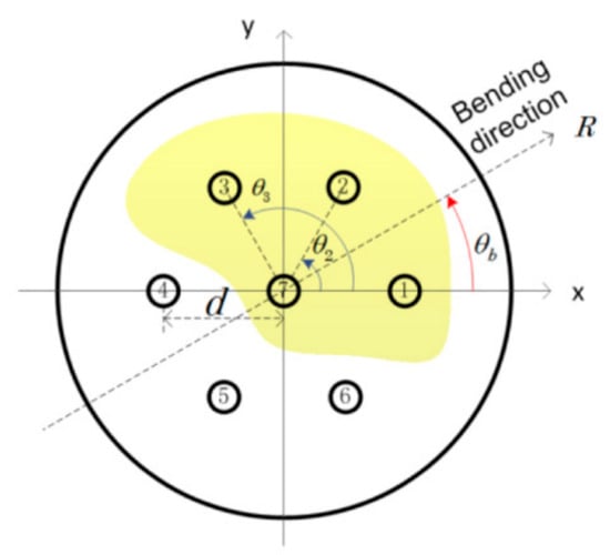
In addition to the advantages mentioned above, note that the bending-induced local tangential strain is dependent on the bending direction and curvature [
8], which can be described as
where
εi and
εj are the bending-induced local tangential strain in core
i and core
j of the MCF.
di and
dj are the distances between the two cores and the center of the MCF, respectively. For symmetrical fiber cores in the MCF,
di and
dj can be regarded as the same.
R is the radius of applied fiber bending, and
θb and
θi are, respectively, the angle of the bending direction and the angular position of core
i. As shown in
Figure 4, an example is given with the transverse geometric distribution of seven-core fiber. Thus, when the bending direction
θb is changed under the same bending radius, the strain difference
Δε between the interference cores will change. As a result, the optical path difference between the interference arms will change with the bending direction, as well as the wavelength shift of the interference spectrum, i.e., the curvature sensitivity of the MMI has direction dependence, which can be used for vector-bending measurements that can measure the curvature and bending direction.
Figure 4. Transversal distribution of the fiber cores with the definition of the important geometrical parameters in seven-core fiber [
8].
In 2006, Libo Yuan et al. demonstrated a curvature sensor based on dual-core fiber MMI [
19], where fiber bending gave rise to the change in the optical path difference of the reflected light in the Michelson interferometer. For dual-core fiber, when the bending direction is perpendicular to the plane of the two cores, the cores will not suffer the tangential strain and exhibit no bending response, so, normally, it can only be used for one-dimensional curvature measurement. To solve this problem, by simultaneously measuring two Michelson interferometers based on two dual-core fibers, which are placed with the two planes of fiber cores arranged vertically, a directional flow velocity sensor was demonstrated by Libo Yuan in 2008 [
22]. Thanks to the long interference arms and controllable optical path difference, MMIs have been widely developed for bending [
11,
19,
22,
35,
40,
41] and vibration sensing [
17,
42], with high sensitivity, a large dynamic sensing range, direction distinguishment ability, and low cross-sensitivity.
On the other hand, by utilizing the change in phase difference between the cores of MCF that is caused by dynamic bending, the MMI has also been used for vibration detection [
17,
42]. As shown in
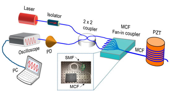
Figure 11, in 2018, Zhiyong Zhao et al. proposed a vibration sensor based on a seven-core fiber Michelson interferometer, where a fan-in coupler was used to couple light from different single-mode fiber pigtails to each core of the MCF, and two cores were selected to construct the in-fiber integrated Michelson interferometer. By monitoring the output power and calculating the fast Fourier transform of the acquired vibration signal, the frequency of variation can be retrieved [
17]. Since the Michelson interferometer is not fabricated by splicing or tapering the fibers, it has the outstanding advantages of ultra-compact size and high mechanical strength. In addition, benefiting from the high sensitivity to bending, variation can cause a remarkable phase shift in the MMI, and in 2011, Feng Peng et al. demonstrated an accelerator by measuring the phase shift amplitude of the MMI, which possesses the advantages of small size, light weight, and immunity to electromagnetic interference in comparison with a traditional electrical accelerometer [
42]. Furthermore, since both cores can be affected equally by the variation in temperature, the accelerator is intrinsically immune to environmental temperature changes, which enables high-precision acceleration measurement.
Figure 11. Experimental setup for the MMI vibration sensor [
17]. PD: photodetector; PC: personal computer. The inset shows the packaged MCF fan-in coupler.
In addition to the fiber deformation-related measurement mentioned above, the change in the surrounding environment, i.e., refractive index and temperature, can also lead to OPD variation between the side core and the center core of MCF. The light in the side core can interact with the surroundings, while the center core remains less sensitive to the external environment, which leads to the change in OPD and a shift in the transmission spectrum, so the change in surroundings can be retrieved by measuring the wavelength shift [
6,
10,
36]. In 2011, Ai Zhou et al. proposed a refractive index sensor based on an etched asymmetrical dual-core fiber Michelson interferometer [
36]. Partial cladding of the MCF was removed by chemical etching to enhance the refractive index sensitivity. The thinning of the fiber cladding leads to leakage of the side core mode and, finally, increases the OPD and enhances the refractive index sensitivity. In addition to the measurement of refractive index, when the ambient temperature is changed, the effective refractive index of the outer core and the center core will change due to the thermal expansion and thermos-optic effect, while the outer cores are more sensitive to the temperature, and the variation in temperature will result in the increase in OPD. Therefore, this feature of the MMI has also been used to develop temperature sensors [
25,
37,
38].
4. MCF-Based Mach–Zehnder Interferometric Sensors
The Mach–Zehnder interferometer (MZI) has been extensively employed in the field of fiber optical sensing since it has the benefits of simple structure, high sensitivity, etc. Thanks to the good spatial consistency and almost the same optical path length between the cores in homogeneous MCFs, the MCF-based Mach–Zehnder interferometer (MMZI) has the advantages of easy fabrication, compact size, good robustness, and long-term stability in comparison with the MZI composed by SMF. As shown in
Figure 13, in order to couple light into different cores of an MCF to fabricate the MMZI, the commonly used coupling schemes include tapering at the fusion spliced point or splicing a small segment of MMF between the MCF and SMF. The light is divided into different cores of the MCF at the first fusion region, then travels along different cores individually, and couples back together at the second fusion point and generates interference. Despite resembling the operating principle of the Michelson interferometer, the interference of the MZI is generated by transmitted light instead of reflective light, usually enabling the MZI to have a higher signal-to-noise ratio than the MI. In addition, due to the outstanding advantages of the MMZI, i.e., compact size, simple configuration, easy fabrication, long-term stability, high sensitivity, etc., MMZIs have been widely used for sensing applications of various parameters, which can be classified into bending-related parameters and environmental parameters. In recent years, some novel sensor applications based on the MMZI have been proposed, such as vital signs monitoring [
43], microsurgery [
44], and distributed vibration sensing [
45], showing the prospects of the MMZI in practical application scenarios. Moreover, multicore photonic crystal fibers have also been widely used for MMZIs, and have been developed for measuring temperature [
46], strain [
47], hydraulic pressure [
48], refractive index [
49], gas [
50], bending [
51], etc.
Figure 13. Schematics of the typical coupling methods of the MCF-based Mach–Zehnder interferometer. (a) Tapering the MCF at the fusing point, (b) fusing a segment of MMF between the SMF and MCF.
Similar to the MCF-based Michelson interferometer, the long interference arms and controllable optical path difference enable the MMZI to be widely used for bending-sensing applications [
12,
23,
51,
52,
53,
54,
55,
56,
57,
58,
59,
60,
61,
62,
63,
64,
65,
66,
67,
68,
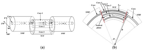
69]. In 2019, Lei Deng et al. proposed a directional bending sensor with the structure of a three-core-fiber-based MZI, as shown in
Figure 14a [
53]. By laterally offset-splicing a segment of three-core fiber (TCF) between two SMFs, the light can be split into two cores of the TCF from the input SMF and then pass through the TCF before coupling into the output SMF to generate interference. As shown in
Figure 14b, with bending applied, the side core and the inner core will be stretched and extruded, respectively, leading to variation in the optical path difference between the two arms of the MMZI [
53]. As a result, the optical path difference will lead to a shift in the interference spectrum, and eventually, the curvature can be retrieved from the wavelength shift. By making use of the same principle in Equation (9), where the strain difference
Δε between the interference cores is dependent on the bending radius and direction, the wavelength shift of the interference spectrum will change with the variation in bending direction. Thus, the curvature sensitivity of the MMZI will exhibit direction dependence, which allows for directional bending sensing [
53,
65,
66]. Apart from the bending direction discrimination ability, since the symmetrical cores of MCF have the same sensitivity to their surroundings, e.g., ambient temperature, a curvature sensor with low-temperature cross-sensitivity has been demonstrated [
52,
62,
65], which can compensate for the temperature perturbations and enhance the accuracy of curvature measurement. Moreover, it has been demonstrated that tapering the sensing part of MCF can increase the leakage of the high-order mode of each core to enhance the bending sensitivity. In 2021, Yancheng Ji et al. demonstrated an extremely sensitive curvature sensor with a sensitivity of 174.02957 nm/m
−1, which is three or four orders higher than a normal MMZI. The ultrahigh sensitivity of the curvature sensor was achieved due to the structure of the tapered seven-core fiber MMZI, in which the waist diameter of the sensing part was reduced to about 2 µm [
62]. In addition, the high sensitivity of bending sensing also enables the MMZI to be used for vibration detection, which has great potential in practical applications, e.g., the long-term monitoring of construction, mechanical structures, and so on [
43,
70,
71]. As shown in
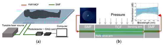
Figure 15, in 2020, Fengze Tan et al. proposed contactless vital signs monitoring, based on few-mode fiber and MCF interferometers [
43], where the interferometer is placed under the mattress. Human breathing and heartbeat change slightly the pressure that applies to the interferometer, which eventually causes variation in the output waveform. Because of the inherent frequency difference between respiration and heartbeat, the raw data are filtered to recover respiration and heartbeat signals, respectively.
Figure 14. (
a) Schematics of a three-core-fiber-based MZI for directional bending sensing. (
b) An illustration of the bent three-core MZI [
53].
Figure 15. (
a) Illustration of the vital signs monitoring experiment. The twin-core fiber (TCF)-based MZI is placed under the mattress. DAQ: data acquisition. (
b) Schematic diagram of twin-core fiber MZI vibration sensor; the inset shows the interference spectrum of the measured twin-core-fiber-based MZI [
43].
The unique structure of MCF enables the MMZI to measure torsion, as well [
7,
21,
72,
73,
74]. For example, in 2018, Hailiang Zhang et al. proposed an MMZI-based torsion sensor fabricated by a helical seven-core fiber, in which the side cores are twisted into a spring structure and the center core is almost straight [
21]. When external torsion is applied to the fiber, the photo-elastic effect results in a refractive index change in the side cores and cladding, but since the center core is located in the neutral axis of the fiber, theoretically, the torsion-induced refractive index change in the center core is much smaller, and as a result, the change in phase difference between the arms leads to a wavelength shift in the interference spectrum. Due to the photo-elastic effect, the refractive index of the side-core has a positive dependence on the twist rate. Since clockwise and counterclockwise twists give rise to different twist rate variations, i.e., either an increase or decrease in the twist rate, the torsion direction can be determined from the wavelength shift direction of the interference spectrum. As a result, torsion direction discriminative measurement is enabled by using the pre-twisted seven-core fiber MZI sensor. Additionally, since axial strain can also result in variation in the twist rate and the refractive index of the side cores, the helical seven-core-fiber-based MZI can also be used to measure axial transverse strain [
75]. Moreover, by making use of the multiple channels in the MCF to generate multiple-path interference, which may have differential responses to external perturbations, e.g., the center core and the side core have different temperature sensitivities, the MCF-based MMZI can achieve multi-parameter measurement.
Similar to the MCF-based Michelson interferometric sensors, in addition to the curvature/strain-related parameters, such as bending, vibration, axial strain, and torsion, the MMZI is also capable of measuring surrounding environmental parameters, such as refractive index [
28,
29,
77,
78,
79,
80,
81,
82,
83,
84,
85], ammonia concentration [
27], salinity [
86], temperature [
26,
87,
88,
89,
90], magnetic field [
91], etc. Because the side cores are usually more sensitive to external disturbances, while the center core remains less sensitive to the external environment, which leads to the change in OPD between the cores and a shift in the transmission spectrum when an environmental parameter changes, the change in external parameters can be retrieved by measuring the wavelength shift of the interference spectrum. On the other hand, etching the cladding or tapering at the sensing region of the MCF can reduce the thickness of the fiber cladding and cause mode leakage of the side cores, which has been used for sensitivity-enhanced refractive index sensing [
29,
77,
78,
79,
80,
81,
82,
83,
84,
85] and temperature sensing [
26,
87,
88]. Furthermore, by using special materials to coat the etched or tapered MCF, the sensing sensitivity of targeted parameters can be further improved [
26,
27,
82,
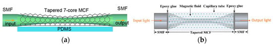
91]. For example, the graphene coating can be regarded as a high-index monolayer, which can enhance the evanescent field and increase the interaction between the side cores and the ambient refractive index. In 2020, Donglai Guo et al. proposed a refractive index sensor fabricated by coating the tapered MCF with graphene, as shown in
Figure 17, and the result verifies that the evanescent field could be enhanced and the refractive index sensitivity could be improved [
82]. In addition to graphene, magnetic fluid is another material that has been widely used to develop MCF sensors. Magnetic fluid is a kind of colloidal solution with magnetic nanoparticles that can aggregate into clusters directly under the applied magnetic field and change the ambient refractive index. In 2018, Chunxia Yue et al. proposed a magnetic sensor fabricated by immersing a segment of tapered MCF into magnetic fluid, as shown in
Figure 17b. By measuring the refractive index variation of the magnetic fluid with a tapered MMZI instead of the conventional method of measuring the Faraday rotation of the light, a high-sensitivity MMZI-based magnetic field sensor was achieved [
91].
Figure 17. (
a) Schematics of the tapered-MMZI-based refractive index sensor, in which the tapered part of the MCF is graphene-coated [
82]. PDMS: polydimethylsiloxane substrate. (
b) Schematic of the tapered-MMZI-based magnetic-field sensor, in which the sensing part is immersed in epoxy glue filled with the magnetic fluid [
91].
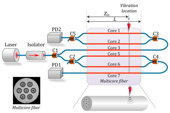
In addition to the point sensors, the MCF-based Mach–Zehnder interferometer can also be used for distributed sensing. Due to the spatial length consistency of cores in the MCF, it can be used to implement an MZI that has very long-distance arms. For example, in 2021, Zhiyong Zhao et al. proposed a novel long-range distributed dual MZI vibration sensor, which consisted of two counter-propagating interferometers that were space-division multiplexed in different cores of a weakly coupled seven-core fiber, as shown in
Figure 18 [
45]. The dual MZI vibration sensor can determine the vibration location through the time-delay difference of two vibration signals in the two MZIs by calculating the cross-correlation of the acquired data, and no additional complicated data processing is required. Since forward-transmitting CW light rather than weak backscattering light is used, together with the advantages of simple structure, a high signal-to-noise ratio, and high sensitivity, the proposed MCF-based dual MZI vibration sensor shows great potential in the application of ultra-long-distance distributed sensing.
Figure 18. Schematic diagram of the proposed long-range distributed vibration sensor. The inset shows the cross-sectional view of the MCF used. C1–C5: optical couplers [
45].
5. Supermode Interferometer-Based (SMI) Sensors
Light transmits independently in different cores of a traditional weakly coupled multicore fiber (MCF), with low crosstalk between cores due to large core-to-core distance. However, in recent years, a new type of strongly coupled multicore fiber with intentionally closely arranged cores has also been proposed, which supports a special mode guiding status, i.e., supermode [
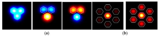
92]. The supermode usually has a large effective area because it can be regarded as a superposition of isolated modes of each MCF core. As an example,
Figure 19 shows the simulated optical field distribution of supermodes that are excited in three-core fiber and seven-core fiber, respectively [
93,
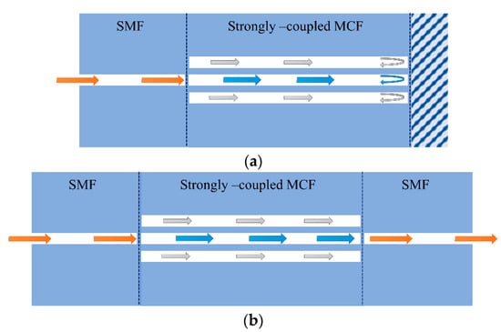
94]. The strongly coupled multicore fiber is considered a form of multimode fiber, in which the supermodes can be used to develop modal interferometers for sensing applications. Typical supermode interferometric sensors include transmissive and reflective structures, as shown in
Figure 20, i.e., SMF–MCF–SMF (SMS) transmissive structure and SMF–MCF reflective (SMR) structure. The difference in the propagation constants of the supermodes will cause a phase difference in transmission, so the MCF acts in a similar manner to a directional coupler [
95,
96] and the interference spectrum of the SMI exhibits a periodic maximum and minimum. The changes in fiber length, internal stress, and the effective refractive index of the supermodes will alter the interference spectrum of the interferometer and the coupling power of the supermodes, which can be used to retrieve the sensing parameters. Since different supermodes in the MCF have distinct propagation constants and different sensitivities to external environmental parameters, the external environmental variation can also result in a phase difference between the supermodes, which can be used for the detection of surrounding environmental parameters such as temperature [
97,
98,
99,
100,
101,
102,
103,
104], refractive index [
105], and, simultaneously, temperature and refractive index sensing [
106].
Figure 19. Simulated supermodes in the strongly coupled MCF. (
a) The orthogonal supermodes in the three-core fiber [
93], and (
b) the center-core supermode and the symmetrical side-core supermode in the seven-core fiber [
94].
Figure 20. Schematics of a supermode interferometer with (a) a reflected structure; (b) a transmitted structure.
Thanks to the large spatial distribution of the fiber mode field of supermodes, bending will easily distort the mode field, which can change the mode loss of each supermode and the phase difference between the supermodes. As a result, bending will result in wavelength shifts [
93], light power variation [
15], and fringe visibility changes [
107] in the SMI, which has been widely used for the high-sensitivity measurement of bending/strain-related external perturbations, such as bending [
15,
93,
94,
95,
96,
107,
108,
109,
110,
111,
112], vibration [
16,
18,
20,
113,
114,
115,
116,
117], and strain [
118,
119]. Furthermore, by using an MCF with asymmetrically distributed cores, the SMI can be used to sense the bending direction.
In addition to the bending and strain sensing applications, supermode interferometers are also capable of sensing the bending-related dynamic parameters, i.e., vibration [
16,
18,
20,
113,
114,
115,
116,
117]. Due to the large mode spatial distribution of SMIs, bending can easily cause variation in the interference spectrum and the output optical power. Thus, by monitoring the wavelength shift through a high-speed spectrometer [
18,
20,
113,
114,
115,
116,
117] or detecting the output optical power variation [
16,
20], the vibration frequency can be retrieved through the fast Fourier transform (FFT) of the time domain signal.
This entry is adapted from the peer-reviewed paper 10.3390/s23073436