Your browser does not fully support modern features. Please upgrade for a smoother experience.
Please note this is an old version of this entry, which may differ significantly from the current revision.
Frequency-difference-stabilized dual-frequency solid-state lasers with tunable and large frequency difference have become an ideal light source for the high-accuracy absolute-distance interferometric system due to their stable multistage synthetic wavelengths.
- dual-frequency solid-state laser
- frequency-difference stabilization
- quadrature-demodulated Pound-Drever-Hall method
1. Frequency Difference Stabilization of Birefringent Dual-Frequency Solid-State Lasers
As described above, a kind of birefringent dual-frequency solid-state lasers has a single-axis configuration, and the frequency difference or beat-note stabilization has been investigated [1][2][3][4][5], the methods of which mainly include frequency-shifted optical feedback, saturable absorption, etc.
In 2007, the research group of L. Kervevan of France reported an original approach to stabilize the beat-note of a 1.53 μm dual-frequency Yb:Er glass laser via an optical self-injection process [6], as shown in Figure 1, in which the dual-frequency Yb:Er glass laser could output a dual-frequency laser at 1.53 μm with a beat-note of nearly 170 MHz. The optical self-injection process consisted of selecting one of the two linear modes as a master oscillator with a polarization filter, then frequency shifting the optical wave using an external acousto-optic modulator, and finally, using it to inject the other mode.
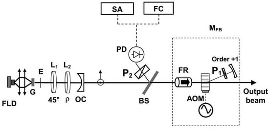
Figure 1. Schematic of self-injection stabilization process for 1.53 μm dual-frequency phosphate glass laser [6]. FLD: fiber-pigtailed laser diode; G: Yb:Er glass plate; E: intracavity etalon; L1 and L2: quarter-wave plates; P1 and P2: linear polarizers; OC: output coupler; BS: beam splitter; FR: Faraday rotator; AOM: acousto-optic modulator; PD: photodiode; SA: spectrum analyzer; FC: frequency counters; MFB: optical feedback module; ρ: angular adjustment.
When the frequency-shifted optical beam was correctly reinjected into the oscillating mode of the laser cavity, the stability of the locking technique was tested by recording the beat note versus the synthesizer frequency, as shown in Figure 2a. It corresponded to a slow frequency deviation of about 0.27 mHz/s. A linear fit was applied to the measured synthesizer frequency [straight line in Figure 2a], and the difference between this reference line and the optical beat-note was observed in the histogram plotted curve in Figure 2b. It can be seen that a fitted Gaussian distribution curve allowed for estimating the stability of the frequency locking to be less than 0.25 Hz.
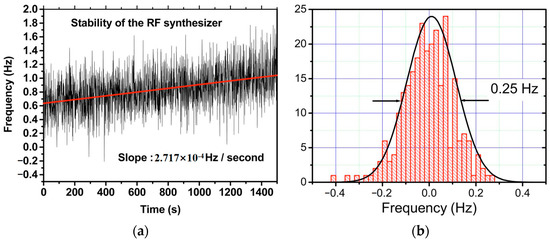
Figure 2. Schematic of self-injection stabilization process for 1.53 μm dual-frequency phosphate glass laser [6]. (a) Instantaneous fluctuations and long-term deviation of the synthesizer frequency versus time. (b) Histogram of the temporal stability of the beat note between the two orthogonal modes using the locking technique based on the frequency-shifted optical feedback loop.
2. Frequency Difference Stabilization of TCDFL
Due to the fact that the TCDFL has both standing-wave cavities with two separate output couplers, it is easy to actively stabilize the resonant frequency of each cavity to a common frequency reference so that a high stability of the frequency difference can be obtained.
As a commonly used method, the PDH frequency-stabilization method integrates with the technologies of both electro-optic phase modulation and optical heterodyne detection. In the past few decades, the laser-frequency-stabilizing technologies based on the PDH method have been widely investigated worldwide due to their advantages of fast servo response, low noise, and high-frequency stability [7][8][9][10][11][12].
2.1. Double-Modulator QD-PDH Frequency-Difference Stabilizing System for TCDFL
In 2022, the group reported a frequency-difference-stabilizing system for the diode-pumped TCDFL at 1064 nm using a double-modulator QD-PDH frequency-stabilizing method [13], as shown in Figure 3, which included two sets of QD-PDH frequency-stabilizing subsystems (see parts II and III) that shared the same F-P cavity as the frequency reference, and the magnitude of the frequency difference was required to be an integer number representing times of the free spectral range (FSR) of the referenced F-P cavity.
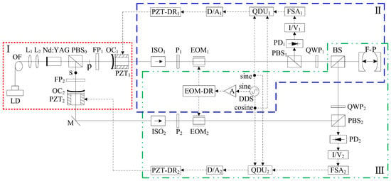
Figure 3. Schematic diagram of the frequency-difference-stabilizing system for the TCDFL using the double-modulator QD-PDH frequency-stabilizing method [13]. LD: laser diode; OF: optical fiber; L: lens; PBS: polarizing beam splitter; FP: F-P etalon; OC: output coupler; PZT: piezoelectric transducer; M: mirror; ISO: optical isolator; P: polarizer; EOM: electro-optic modulator; DDS: direct digital synthesizer; A: amplifier; EOM-DR: EOM driver; QWP: quarter-wave plate; BS: beam splitter; F-P: F-P reference cavity; PD: photodetector; I/V: current-to-voltage; FSA: frequency-selective amplifier; QDU: quadrature-demodulated unit; D/A: digital-to-analog; PZT-DR: PZT driver.
A QD-PDH method-based frequency-difference-stabilizing system for the diode-pumped TCDFL with a frequency difference of 24 GHz at 1064 nm was established and investigated, in which the free spectral range and the finesse of the referenced F-P cavity were equal to 375 MHz and 421, respectively. Both frequencies of the TCDFL were successfully frequency stabilized to the two different resonant frequencies of the F-P cavity during a period of about 1 h, the error signals of the two QD-PDH frequency-stabilizing subsystems were obtained experimentally, as shown in Figure 4, the maximum offset voltages of the QD-PDH error signals were equal to 77 mV and 74.2 mV, respectively, and correspondingly, the laser-frequency drifts of the linear and right-angle cavities were determined to be <0.35 MHz and 0.36 MHz, respectively. The frequency-difference fluctuations of the frequency-locked TCDFL are shown in Figure 5, and the maximum change in the frequency difference was <0.55 MHz. According to the Allan variance, the laser-frequency stabilities of the linear and right-angle cavities were better than 2.3 × 10⁻¹¹ and 2.7 × 10⁻¹¹, respectively, corresponding to a frequency-difference stability better than 4.2 × 10⁻⁷.
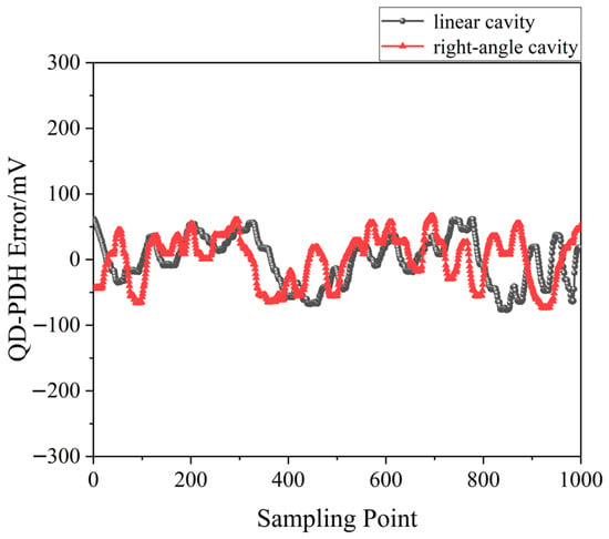
Figure 4. Error signals of the frequency-locked QD-PDH subsystems [13].
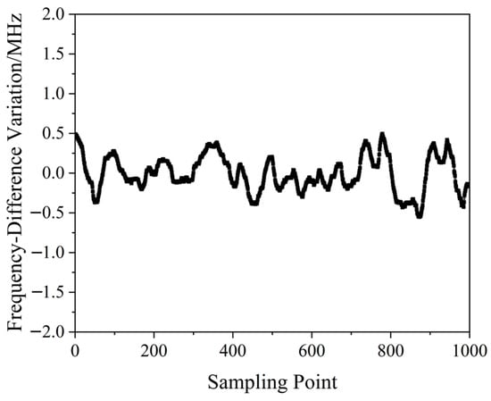
Figure 5. Frequency difference variation in the frequency-locked dual-frequency Nd:YAG laser [13].
2.2. Single-Modulator QD-PDH Frequency-Difference-Stabilizing System for TCDFL
In 2022, our group proposed a new scheme of the phase modulation of the orthogonally and linearly polarized dual-frequency laser using a single electro-optic modulator (EOM), and a simple frequency-difference-stabilizing system for the TCDFL using a single-modulator QD-PDH frequency-stabilizing method was designed [14], as shown in Figure 6, which included two sets of QD-PDH frequency-stabilizing subsystems (see parts II and III) that shared the same electro-optic phase modulation unit and the same frequency reference of the F-P cavity.
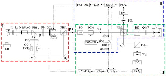
Figure 6. Schematic diagram of the frequency-difference-stabilizing system for the TCDFL using the single-modulator QD-PDH frequency-stabilizing method [14]. LD: laser diode; OF: optical fiber; L: lens; PBS: polarizing beam splitter; FP: F-P etalon; OC: output coupler; PZT: piezoelectric transducer; M: mirror; ISO: optical isolator; EOM: electro-optic modulator; DDS: direct digital synthesizer; EOM-DR: EOM driver; BS: beam splitter; QWP: quarter-wave plate; F-P: F-P reference cavity; PD: photodetector; I/V: current-to-voltage; FSA: frequency-selective amplifier; QDU: quadrature-demodulated unit; D/A: digital-to-analog; PZT-DR: PZT driver.
A QD-PDH frequency-difference-stabilizing system for the same diode-pumped TCDFL with a frequency difference of 24 GHz at 1064 nm was established and investigated. Both frequencies of the TCDFL at 1064 nm were successfully frequency-stabilized to the two different resonant frequencies of the referenced F-P cavity during a period of about 1 h, the error signals of the two QD-PDH frequency-stabilizing subsystems were obtained experimentally, as shown in Figure 7, the maximum offset voltages of the QD-PDH error signals were equal to 84.5 mV and 76.7 mV, respectively, and correspondingly, the laser-frequency drifts of the linear and right-angle cavities were determined to be <0.34 and 0.35 MHz, respectively. The frequency-difference fluctuations of the frequency-locked TCDFL are shown in Figure 8, and the maximum change in the frequency difference was <0.51 MHz. According to the Allan variance, the laser-frequency stabilities of the linear and right-angle cavities were better than 1.6 × 10⁻¹¹ and 2.0 × 10⁻¹¹, respectively, corresponding to a frequency-difference stability better than 2.9 × 10⁻⁷.
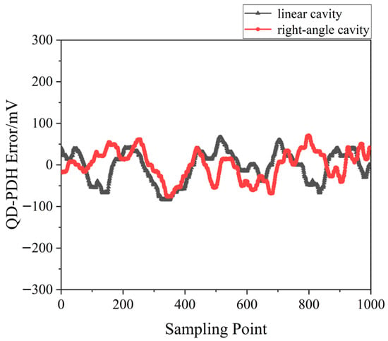
Figure 7. Error signals of the frequency-locked QD-PDH subsystems [14].
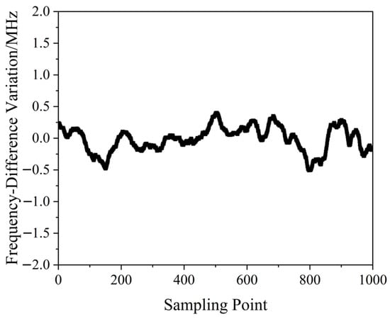
Figure 8. Frequency difference variation in the frequency-locked dual-frequency Nd:YAG laser [14].
The experimental results obtained above indicate that compared with the double-modulator QD-PDH frequency-difference-stabilizing system shown in Figure 3, the single-modulator QD-PDH frequency-difference-stabilizing system shown in Figure 6 is not only simple, but also has better performances in the linear-dynamic range, frequency-discriminating sensitivity, frequency stabilization, and frequency-difference stabilization
This entry is adapted from the peer-reviewed paper 10.3390/s23063206
References
- Brunel, M.; Vallet, M. Wavelength locking of CW and Q-switched Er3+ microchip lasers to acetylene absorption lines using pump-power modulation. Opt. Express 2007, 15, 1612–1620.
- Thévenin, J.; Vallet, M.; Brunel, M.; Gilles, H.; Girard, S. Beat-note locking in dual-polarization lasers submitted to frequency-shifted optical feedback. J. Opt. Soc. Am. B 2011, 28, 1104–1110.
- Rolland, A.; Brunel, M.; Loas, G.; Frein, L.; Vallet, M.; Alouini, M. Beat note stabilization of a 10-60 GHz dual-polarization microlaser through optical down conversion. Opt. Express 2011, 19, 4399–4404.
- Wang, X.H.; Xu, J.L.; Gao, S.F. Frequency stabilization of a dual frequency Yb3+:GdAl3(BO3)4 laser via nonlinear loss modulation in black phosphorus. Laser Phys. Lett. 2017, 14, 065802.
- Pique; Paul, J. Iodine-stabilized high-resolution dual-frequency Ti:sapphire laser. Opt. Express 2018, 26, 16402–16410.
- Kervevan, L.; Gilles, H.; Girard, S.; Laroche, L. Beat-note jitter suppression in a dual-frequency laser using optical feedback. Opt. Lett. 2007, 32, 1099–1101.
- Spencer, D.T.; Davenport, M.L.; Komljenovic, T. Stabilization of heterogeneous silicon lasers using Pound-Drever-Hall locking to Si3N4 ring resonators. Opt. Express 2016, 24, 13511–13517.
- Davila, R.J.; Baynes, F.N.; Ludlow, A.D.; Fortier, T.M.; Leopardi, H.; Diddams, S.A. Compact thermal-noise-limited reference cavity for ultra-low-noise microwave generation. Opt. Lett. 2017, 42, 1277–1280.
- Schmitz, J.; Meyer, H.M.; Köhl, M. Ultraviolet Fabry-Perot cavity with stable finesse under ultrahigh vacuum conditions. Rev. Sci. Instrum. 2019, 90, 063102.
- Yao, B.; Chen, Q.F.; Chen, Y.J.; Wu, B.; Mao, Q.H. 280 mHz linewidth DBR fiber laser based on PDH frequency stabilization with ultra-stable cavity. Chin. J. Lasers 2021, 48, 198–206.
- Jang, Y.S.; Lim, J.K.; Wang, W.T.; Kim, S.W.; Savchenkov, A.; Andrey, B.M.; Wong, C.W. Measurement of sub-fm/Hz1/2 displacement spectral densities in ultrahigh-Q single-crystal microcavities with hertz-level lasers. Photonics Res. 2022, 10, 1202–1209.
- Yu, Y.; Zhang, H.; Wang, D.H.; Yuan, J.B.; Cao, J.; Huang, X.R. Review of precision measurements of the zero-thermal-expansion temperature of ultra-stable cavity. Metrol. Meas. Technol. 2022, 42, 30–37.
- Jiang, F.; Jiao, M.X.; Su, J.; Xing, J.H.; Liu, Y.; Lian, T.H.; Liu, J.N. Design of frequency-difference stabilizing system for two-cavity dual-frequency Nd:YAG laser using quadrature-demodulated Pound-Drever-Hall method. Opt. Eng. 2022, 61, 046109.
- Jiang, F.; Jiao, M.X.; Xing, J.H.; Liu, Y.; Lian, T.H.; Liu, J.N.; Li, H.Q. Design of frequency-difference stabilizing system for two-cavity dual-frequency Nd:YAG laser using single-modulator quadrature-demodulated Pound-Drever-Hall method. Opt. Eng. 2022, 61, 106106.
This entry is offline, you can click here to edit this entry!
