Your browser does not fully support modern features. Please upgrade for a smoother experience.
Please note this is an old version of this entry, which may differ significantly from the current revision.
As an essential source of renewable energy, solar energy systems are broadly characterized as either passive solar or active solar depending on how they capture and distribute solar energy.
- wind
- solar
- green
1. Solar Energy
As an essential source of renewable energy, solar energy systems are broadly characterized as either passive solar or active solar depending on how they capture and distribute solar energy. Solar energy has two typical portions, namely, photovoltaic energy, which is directly converted into electricity and constitutes a smaller percentage, and thermal energy, which is harvested in water or air heating units and constitutes a much larger percentage [1]. Photovoltaic (PV) cells are made from semiconductor materials that eject electrons, when energetic light over a threshold strikes the surface, and produce electrical currents [2]. A wide variety of semiconductor materials can be employed for PV cells. A typical material is silicon. In addition, copper indium gallium diselenide (CuInSe2), cadmium telluride (CdTe), perovskites, and even some organic photovoltaic compounds (OPV) can be utilized [2]. Although PV conversion efficiency is an important metric, in engineering applications, cost efficiency measured by the cost per watt of power must also be considered. Solar PV capacity has grown by nearly 500 times since 2000. In 2020, global PV power capacity grew by over 138 GW and reached 773.2 GW. The top installers of solar power in 2022 were China (307.0 GW), the USA (95.2 GW), and Japan (74.2 GW) [3].
For most available commercial panels, the photovoltaic energy conversion rate is around 15% to 20%, although some researchers have developed photovoltaic (PV) cells with efficiencies near 50% for space applications [2]. However, even with intermediate efficiency, with 0.6% coverage of the land area, PV cells would generate enough electricity to meet the demand in the USA [2].
According to Ref. [4], active solar techniques include the use of photovoltaic systems, concentrated solar power, and solar heating systems; whereas passive solar techniques include orienting a building to the Sun, selecting materials with favorable thermal mass or light-dispersing properties, and designing spaces with more natural air circulations. According to Ref. [4], a photovoltaic solar panel produces electricity in direct proportion to the amount of exposed sunlight. As shown in Figure 1, the sun’s angle in the sky influences the intensity of the light received by the Earth. Thus, the location of the sun directly affects how much energy a solar panel generates. Several factors such as time of day, season, and latitude also determine the sun’s location relative to the panel.
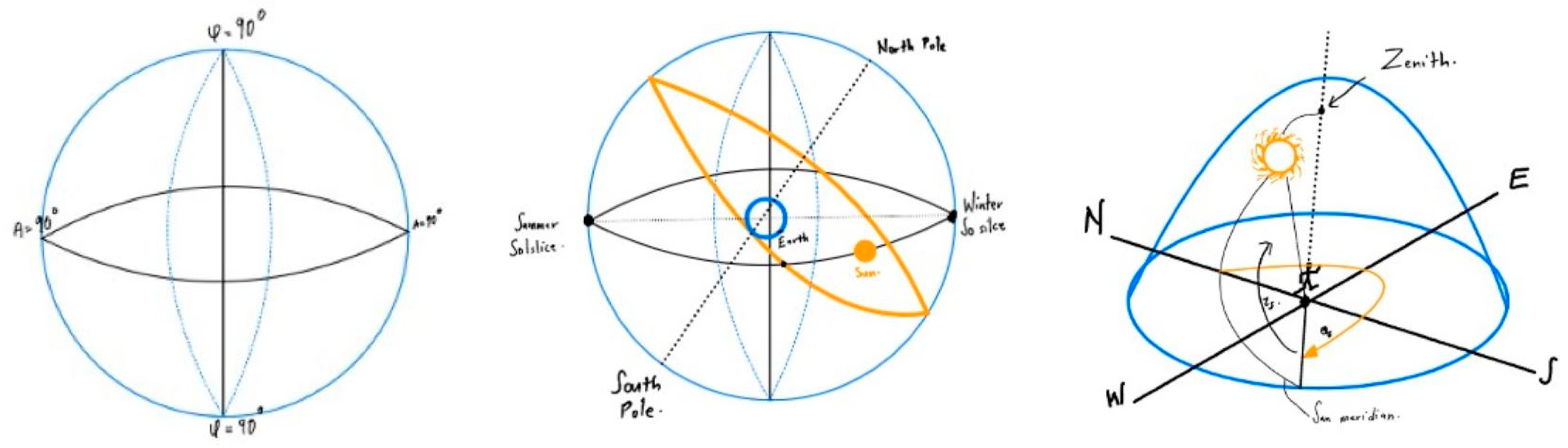
As shown in Ref. [4], when the sun is overhead, its rays are the most direct and intense. As it moves lower in the sky, the same area of light from the sun covers a larger area of the Earth. As the area increases, intensity decreases. Consequently, the solar panel receiving this light produces less electricity. To partially compensate for the intensity reduction, a solar panel is often tilted to match the sun’s angle [5], although the complexity and upkeep of mechanical tracking systems add considerable cost to a solar energy installation. In Ref. [6], a passive solar tracking system is utilized. This passive system developed by Zomeworks is based on the movement of the liquid within the canister-copper tube system and respective gravitational forces.
Of course, the light power and intensity measured by lumen, steradian, and candela can be easily mapped into the power unit Watt [7]. With respect to the latitude, the declination angle (δ) relates to the tilt of the earth’s axis, which is 23.45°. Declination is the angle between an earth–sun line and the equatorial plane. The declination angle is measured north or south of the celestial equator, along the hour circle passing through the point in question. The declination angle varies from positive 23.45 degrees to negative 23.45 degrees as the earth rotates around the sun.
The latitude is an angular value, an expression of positioning north–south from any point on the earth. Longitude is an angular value, an expression of positioning east–west from any point on the earth. The optimum tilt angle of the solar system depends on the positioning of the sun and is defined by the height of the sun (zenith) and the sun’s azimuth. The zenith is an angle between a line that points from the site toward the center of the sun, and the horizon. It is the opposite angle to the sun’s height. The azimuth angle is measured clockwise, between the geographical north and the point on the horizon directly below the sun.
2. Solar Voltaic Portion of Energy
The subjects of the solar voltaic part of energy include photovoltaic (PV) cells, modules, panels, characteristic voltage (V)–current (I) curves, electric power output, efficiency, and DC to AC inverters along with respective advantages and disadvantages. As shown in Figure 2, a photovoltaic panel is a device that produces electrical energy when it is illuminated by a source of light. By placing a PV cell outside directly under the sun, it is possible to generate electrical energy through the use of sunlight. The basic component of a photovoltaic panel is the photovoltaic cell. A photovoltaic cell is primarily a P–N junction mostly made of silicon. A type N semiconductor is doped with Arsenic (As), Antimony (Sb), or Phosphorus (P) with free electrons with negative charges; whereas a type P semiconductor is doped with Gallium (Ga), Indium (In), or Boron (B) with so-called holes or vacancies with positive charges. However, the P–N junctions in PV cells are made up of thin slices of silicon so as to maximize its surface area, thereby allowing PV cells to intercept as much light as possible.
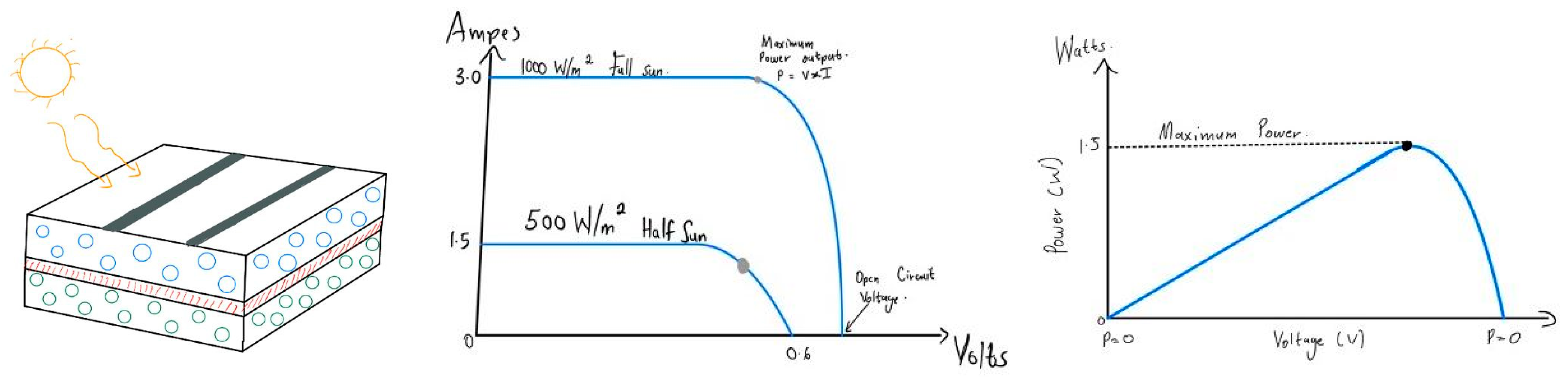
The PV panels usually consist of PV modules fastened to a common frame. Most PV solar cells have a solar rating for the maximum deliverable solar power produced by the cell in watts which is equal to the product of the cell voltage multiplied by the leading cell current. For instance, if the maximum output current output of a single 0.5 Volt silicon photovoltaic cell with a maximum rated power output of 1.75 Watts at the full sun, the maximum current can be easily estimated as 3.5 Amps. Note that the maximum theoretical current as the confirmed or real current is determined by the rate of the incoming solar photons. Moreover, the amount of electrical power generated by the photovoltaic cell depends on solar irradiance and environmental conditions such as temperature and cloud cover. The power rating of a solar cell is expressed in Watts (W), which refers to the maximum or peak power delivered by one cell at the full sun with full exposure to sunlight.
PV cells, when illuminated, are equivalent to a source of current parallel with diodes. In order to produce more electrical power from photovoltaic solar cells, we need to either increase the photovoltaic effect and the energy of photons or produce a different type of cell that is more efficient at converting solar energy into electricity. The amount of electric power provided by a PV cell depends on the point on the V–I curve at which the PV cell operates. The point on the V–I curve where the photovoltaic cell output power is maximum is referred to as the maximum power point (MMP). It is important that the PV panels operate at maximum power point in order to maximize the amount of energy produced. Notice, however, only a small portion of the energy from the incident light could be converted into electrical energy whereas the majority of the energy is locked in the so-called solar thermal energy part. The more productive or efficient the PV cells in the PV module or panel are, the higher the amount of electric power would be produced. The efficiency of PV modules or panels is usually calculated using the characteristic E–I curve under standard test conditions. The formula is given below as
ɳ = [(MPP)/(Irradiance × A)] × 100,
The three most commonly used SI radiometric units describe the effectiveness of radiation coupling between a light source and an optical system, namely, (1) Radiance; (2) Irradiance; and (3) Radiant Flux. Radiance is often casually called “brightness”, a term used in photometry to describe the perception of human eyes looking at a light source. Irradiance is the radiometry term for the power per unit area of electromagnetic radiation incident on a surface. Irradiance is sometimes called intensity with a unit watts per square meter (W/m2), or milliwatts per square millimeter (mW/mm2); whereas Radiant Intensity is measured in watts per steradian (W/sr). Irradiance is the amount of light energy from one emitting object hitting a square meter of another each second. Photons that carry this energy have wavelengths from energetic X-rays and gamma rays to visible light to infrared and radio. Solar irradiance is the output of light energy from the entire disk of the Sun, measured at the Earth [8].
An inverter is a device that changes direct current (DC) power stored in a battery to standard 120/240 VAC electricity. Most solar power systems generate DC which is stored in batteries. In an inverter, direct current (DC) is switched back and forth to produce an alternating current (AC). Then, it is transformed and filtered into an acceptable output waveform such as a sine wave. The final product becomes a waveform that is acceptable to all loads without sacrificing too much power in the conversion process. Solar panel specifications include KC50TM high efficiency multi-crystal photovoltaic module with an efficiency of over 16%, maximum power of 50 Watts, the voltage at a maximum power of 17.9 Volts, current at a maximum power of 2.80 Amps, open circuit voltage of 21.8 Volts, short circuit current 3.35 Amps, series fuse rating 6 Amps, dimension 25.2 by 25.7 by 2.1 inches, and weight 16 lbms.
3. Solar Thermal Portion of Energy
Another more significant portion of solar energy is in the thermal energy form. A solar thermal system is designed to capture the Sun’s radiant energy and convert it into heat (thermal energy) by transferring or exchanging the heat to and from a fluid (liquid or gas). In practice, water and air are the two most commonly used fluids in existing solar thermal systems. It is worth noting that nearly fifty years ago, amid the Arab oil embargo, which had caused a national energy crisis during President Jimmy Carter’s administration, thirty-two solar panels were installed on the White House roofs for thermal solar energy [9]. Regrettably, they were removed in the next administration. One route for harnessing solar thermal energy to produce electricity is to use concentrated solar power (CSP). The world’s first commercial solar thermal power plant came online in Spain in 2007. Projections from the International Energy Agency are that the share of renewable electricity generation from solar energy will increase from 0.3% in 2011 to almost 0.6% in 2018 and 17% in 2021, of which about one-tenth will be from CSP [10].
All concentrating solar power (CSP) technologies use a mirror configuration to concentrate the sun’s light energy onto a receiver and convert it into heat. The heat can then be employed to create steam to either drive a turbine to produce electrical power or directly serve as process heat in manufacturing for heavy industries [11]. In most solar thermal energy collectors, sunlight shines through the glass or silicon panels. Some of the light, in particular, longwave radiation, is reflected or refracted. However, most of the light, in particular, shortwave radiation, passes through the glass and onto the dark-colored collection material where a large portion of the radiant electromagnetic energy is absorbed and converted into thermal energy or heat. In practice, heat is thermally transmitted from the absorber material to the copper tubing via physical contact, conduction, or convection. Notice that the copper thermal conductivity is much higher than aluminum, steel, or PVC-type materials. The collected heat conducts through the copper tubing to the fluid inside the pipe system. As the fluid (water or air) moves through the tubing, the conducted heat is transmitted to other parts of solar thermal systems, as shown in Figure 3.
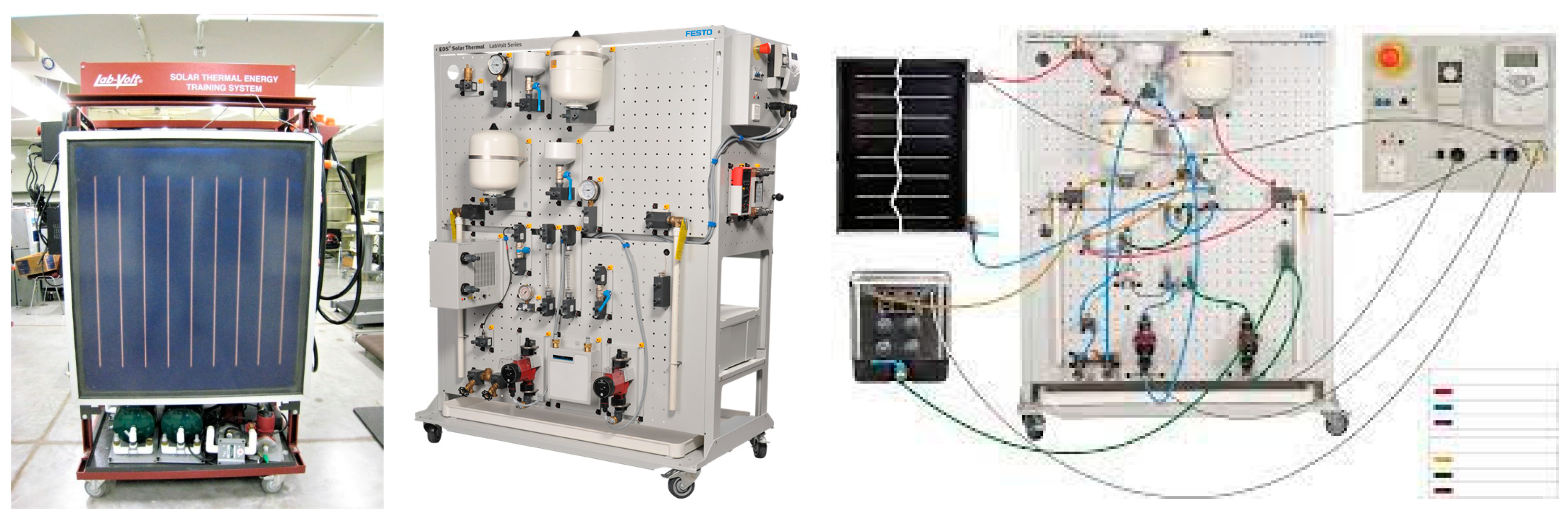
Figure 3. Different LabVolt solar thermal energy collectors [12].
The clear glass panels are often double-glazed and manufactured with a minimum amount of iron content in order to pass a larger spectral portion of infrared energy. In addition, thermal insulation placed below and on the sides of the absorber material helps to minimize thermal losses or the inadvertent heat transfer to the ambient air that surrounds the solar collector enclosure. Moreover, baffles and manifolds are used to increase surface area and to control the flow of fluid through the solar collector in such a way as to improve thermal transfer efficiency. There are many different types of solar collectors in use today. In general, there are passive air collectors and active water collectors which can also be connected in parallel and series, as shown in Figure 4.
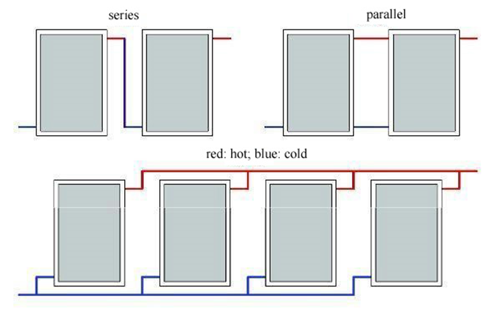
Figure 4. Solar thermal panels are connected in series and parallel [12].
The integrated collector storage or solar batch heater is suitable for moderate climates; this simple collector uses its internal water tank or multiple tanks for both collection and storage of solar heat. Each tank is coated to absorb solar energy, and the entire assembly is enclosed in a thermally insulated and glazed box. One such system is the so-called thermo-siphoning water panel, essentially a flat-plate type of convection heat storage system that requires storage tank placement above the collector. Similarly, a thermos-siphoning air panel is a glass window upon a vertically positioned and well-insulated box with a dark-colored interior that allows the air inside to become heated by the sun. Natural convection causes the air to flow from bottom to top. The evacuated tube is another convection heat storage system that also requires storage tank placement above the collector. The heat pipe style uses long borosilicate glass tubes with pure copper tube absorbers called heat pipes inside to indirectly heat an insulated copper manifold at the top of the unit by way of evaporated heat pipe fluid. The purified water with additives boils at only 86°F due to an internal vacuum. The cooled vapor forms back into a liquid by way of condensation and such heating processes repeat continuously. A vacuum between the clear outer glass and an aluminum nitride-coated inner glass absorber tube virtually eliminates heat loss by natural convection, so these units are highly efficient. The vacuum is maintained by a barium coating at the bottom of each tube normally silver in color; a cloudy white coloring at the tube end indicates a loss of vacuum.
Solar thermal panels or arrays can be configured or connected in series or in parallel as illustrated in Figure 4 to increase volume or flow rate, respectively. Although series configuration is not normally used in residential applications due to the high-temperature elevation through the sequential heat from the solar thermal energy, the high water temperatures from series-connected arrays are sometimes required for commercial installations. Moreover, for systems in series or parallel, basic plumbing techniques are used to interconnect the solar collector panels. The use of brass unions permits easy collector replacement and can minimize rooftop soldering. Several key factors determine the required size or capacity of a solar collector array for any given thermal system, which includes the required solar power, the available space, and the collector orientation. In general, the array must have a large enough surface area to capture the required solar power for a particular geographical location. In addition, unless a ground installation is planned, the entire array must be sized correctly to fit properly on the building’s roof. The space required to mount the solar collector array on a roof also depends upon the roof pitch versus the tilt angle required for each solar collector. The site latitude essentially equals the optimal solar collector tilt angle for year-round operation with about 10° subtracted to compensate for weather variations. In the Northern Hemisphere, for winter operation only, add 15°, or for summer operation only, subtract 15°. The rise and run ratio depends very much on the roof pitch angle. In general, the 20 to 12 ratio is set for 60°; the 12 to 12 ratio is set for 45°; the 7 to 12 ratio is set for 30°; the 4 to 12 ratio is set for 18°; and 0 to 12 ratio is set for 0°.
Heat pipes require a minimum tilt angle of 25° to operate properly. The direct flow style heats liquid directly inside the inner glass tube, which contains a long copper feed tube that forces the liquid up through the glass tube. This style is not normally passive in operation. It typically requires an active circulator pump. Unlike heat pipe designs, if the glass tube breaks due to freezing conditions, the thermal transfer fluid can escape and drain the system. These units, and similar devices, called U-tube/U-pipe collectors can be positioned between 0° and 90°. In a U-pipe design, a U-shaped copper tube inside the inner glass tube contains the thermal transfer fluid. No liquid enters the glass vacuum tube, so breakage is less common and not as critical. A window box is a flat-plate type of collector, it is a smaller version of an air panel that fits inside a window exposed to the sun. Matrix is also similar to the flat plate; this collector uses an absorber material with a large amount of total surface area, such as expanded metal lath or fiberglass fibers within an insulated enclosure. A glass window on the box top exposes the dark-colored material inside to heat the internal air. Designs that restrict airflow should only be used in active systems. A solar chimney is a large structure that uses sunlight and natural convection to heat and move the inside air.
A flat-plate active water collector is very common for residential and commercial buildings, due to their high efficiency and low cost. It uses a grid of copper tubing inside a thermally insulated enclosure. A glass window on the top exposes dark-colored copper fins or aluminum sheeting as an absorber plate that is thermally connected to the flow tubes. Water flow is forced through the tubing by a motorized electric pump. The flat-plate active air collector uses baffles to direct airflow through a grid within a thermally insulated enclosure.
Glazing is not required for the low-temperature rises typically needed to warm swimming pools, hot tubs, and spas. The water is commonly pumped between the pool and the collector via the water filter system. The total collector area is typically sized to half of the pool surface area for the purpose of heating the entire pool. A rock box is a glass window upon an insulated and stone-filled box that allows the air flowing inside to become heated by the sun-warmed rocks. Airflow is forced by an electric blower fan. This collector uses an absorber material with a large amount of total surface area, such as expanded metal lath or fiberglass fibers within an insulated enclosure. A glass window on the box top exposes the dark-colored material inside to heat the internal air. Designs that permit plenty of airflows can also be used in passive systems. During radiant-to-thermal energy conversion, the amount of surface area exposed to the sun is the largest single contributor to solar collector efficiency. In addition, high flow rates that keep low-temperature differentials between the solar fluid and ambient air are usually more efficient than low flow rates and high-temperature differentials. For larger industrial operations, solar thermal energy can also be collectors with parabolic troughs or parabolic dishes. In the largest installation so far, a combined unit with parabolic dish-shaped individual mirrors or silicon panels is introduced with the tower full of salt to be melted by the solar thermal energy and eventually used to power the steam engine for the production of electricity. In this combined form, both solar voltaic energy and thermal energy are harvested.
There are a few mechanisms based on which the solar system can generate power. Concentrating solar power (CSP) plants typically integrate thermal energy storage systems in order to generate electricity during cloudy periods or for hours after sunset or before sunrise. This ability to store solar energy makes CSP a flexible and dispatchable source of renewable energy [13].
CSP plants can be broken down into two groups, based on whether the solar collectors concentrate the sun rays along a focal line or on a single focal point with much higher concentration factors. Line-focusing systems include parabolic trough and linear Fresnel plants along with single-axis tracking systems. Point-focusing systems include solar dish systems and solar power plants along with two-axis tracking systems to concentrate the power of the sun [14]. The earliest CSP technology in use is a parabolic trough, and the fastest-growing technology is the tower with concentrating mirrors and molten salt, as shown in Figure 5. Molten salt is employed because its specific heat is much higher than water or air [13].
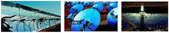
Power towers or central receiver systems utilize sun-tracking mirrors called heliostats to focus sunlight onto a receiver at the top of a tower [5]. A great deal of research has been conducted in exploring various heat transfer or energy storage materials ranging from air to alternative mixtures of chemicals to attain higher temperatures which gain higher efficiency and yield lower costs.
In a parabolic trough CSP system, the sun’s energy is concentrated by parabolic curved, trough-shaped reflectors onto a receiver pipe, namely, the heat absorber tube running along about a meter above the curved surface of the mirrors. The temperature of the heat transfer fluid flowing through the pipe, usually thermal oil, is increased from 293 °C to 393 °C, and the heat energy is then used in the thermal power block to generate electricity in a conventional steam generator.
A trough solar collector field comprises multiple parabolic trough-shaped mirrors in parallel rows aligned to enable these single-axis trough-shaped mirrors to track the sun from east to west during the day to ensure that the sun is continuously focused on the receiver pipes as shown in Figure 6. As of 2018, 90% of the concentrating solar power (CSP) in commercial operations is generated through trough-shaped mirrors.

Like troughs and towers, the key operating parameters of which are listed in Table 1, the so-called Fresnel system, a parabolic dish system consisting of a parabolic-shaped point focus concentrator in the form of a dish that reflects solar radiation onto a receiver mounted at the focal point, can also be incorporated to generate steam for direct use. These concentrators are mounted on a structure with a two-axis tracking system to follow the sun. The collected heat is typically utilized directly by a heat engine, with either a Stirling or Brayton power cycle, mounted on the receiver moving with the dish structure. The dish can attain extremely high temperatures and holds promise for use in solar reactors for making solar fuels which require very high temperatures.
Table 1. Specific energy and storage requirements for different green energy systems [1].
| Parabolic Trough | Solar Tower | |
|---|---|---|
| Typical Capacity (MW) | 10–300 | 10–200 |
| Tech Development Risk | Low | Medium |
| Operating Temp (℃) | 350–550 | 250–565 |
| Plant Peak Efficiency (%) | 14–20 | 23—35 |
| Annual Net Efficiency (%) | 11–16 | 7–22 |
| Storage System | Indirect or Direct | Direct |
| Grid Stability | Medium to High | High |
| Storage with Molten Salt | 380 °C or 550 °C | 550 °C |
To be economic, this solar thermal electricity (STE) or concentrating solar power (CSP) installations require abundant direct solar thermal radiation. In fact, only strong direct sunlight can be concentrated to the temperatures required for electricity or heat generation, which limits STE or CSP to hot and dry regions with direct normal irradiance levels (DNI) of 2000 kWh/m2/year or more [14]. STE or CSP plants in areas with higher DNI will have a lower levelized cost of electricity (LCOE). There are a number of global regions with excellent solar resources that are suitable for STE or CSP plants, which include North Africa, the Middle East, Southern Africa, Australia, the western United States, and parts of South America [15]. In practice, the long-range transmission system must be used to transport clean STE from favorable production areas to large consuming areas [7]. Nevertheless, off-grid energies in developing countries, such as solar PV and STE, can transform the lives of those 1.4 billion people currently deprived of access to electricity, and those who can barely rely on their electric grids. Furthermore, solar cooking, solar crop drying, and solar water heating can significantly improve living standards in developing economies. In fact, even in countries with well-developed energy systems, solar technologies can help ensure greater energy security and sustainability [15].
According to Ref. [16], the largest solar farm in the world, Bhadla solar park, which is under construction since July 2015 with a total estimated investment of around 1.4 billion dollars, will be a 2.25 GW solar complex in Bhadla village in Jodhpur district of Rajasthan, India. As shown in Figure 7, the entire solar park spreads over 17 square miles of hot and dry area with an average temperature of around 116 degrees Fahrenheit. As mentioned, too, in Ref. [16], Ecoppia will install approximately 2000 solar panel cleaning robots in the solar park. The first phase of the solar park has seven solar power plants with a combined capacity of 75 MW, which was completed in October 2018. For the next few years, phase two has ten solar power plants with a combined capacity of 680 MW, and phases three and four will have capacities of 1000 MW and 500 MW, respectively. As one of the world’s largest solar farms, Topaz Solar Farm has a 550 MW photovoltaic power station in San Luis Obispo County, California, United States [17].
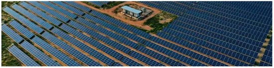
Figure 7. Bhadla solar park in India [16].
According to Ref. [18], the Australia–Asia Power Link combines the world’s largest solar farm and battery storage facility in the Northern Territory, as shown in Figure 8, with a solar array spread over 120 square kilometers and a power capacity of 3.2 GW. With a 5000 km transmission system, renewable electricity is supplied to Darwin, Singapore, and Asian markets at reliable and competitive prices. Based on Ref. [19], Quaid-e-Azam Solar Park in Pakistan has dedicated the land of over 6500 acres in Lal Sohnra, Cholistan, Bahawalpur, as shown in Figure 9, with over 400,000 solar modules and a total solar energy capacity of 1 GW.
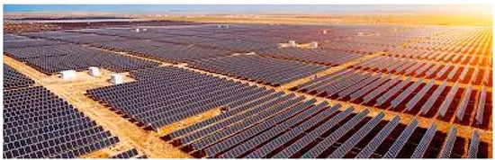
Figure 8. The Australia–Asia Power Link [18].
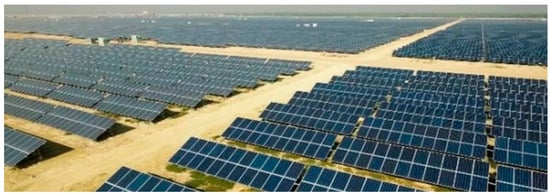
Figure 9. Quaid-e-Azam Solar Park in Pakistan [19].
This entry is adapted from the peer-reviewed paper 10.3390/eng4010052
References
- Total Energies Fondation. Planete Energies. The Two Types of Solar Energy. 2022. Available online: https://www.planete-energies.com/en/medias/close/two-types-solar-energy (accessed on 11 October 2022).
- Center for Sustainable Systems, University of Michigan. Photovoltaic Energy. 2022. Available online: https://css.umich.edu/sites/default/files/2022-09 (accessed on 11 October 2022).
- Solar Power by Country. 2022. Available online: https://worldpopulationreview.com/country-rankings/solar-power-by-country (accessed on 11 October 2022).
- Seattle, P.I. Does the Location of the Sun Affect the Amount of Energy Solar Panels Collect? 2022. Available online: https://education.seattlepi.com (accessed on 14 September 2022).
- MSU Texas BS Mechanical Engineering Program Senior Design Project. Portable Solar Tracker, Matt Capps, Clide Cadette, Leron Marrast, Laura Wittle. Faculty Advisor Dr. Salim Azzouz. 2010.
- MSU Texas BS Mechanical Engineering Program Senior Design Project. Dalquest Water System. Aaron Smith, Nick Moore, Tony Burson, Karu Anto, and Philip Ray. Faculty Advisor Dr. Idir Azouz, 2010.
- Zhu, H.; Blackborow, P. ENERGETIQ. A HAMAMATSU Company. Technical Note: Understanding Radiance (Brightness), Irradiance, and Radiant Flux. 2022. Available online: https://www.energetiq.com/technote-understanding-radiance-brightness-irradiance-radiant-flux (accessed on 30 September 2022).
- Solar Dynamics Observatory. NASA. Solar Irradiance. 2022. Available online: https://www.nasa.gov/mission_pages/sdo/science/Solar%20Irradiance.html (accessed on 30 September 2022).
- Murse, T.; ThoughtCo. A Brief History of White House Solar Panels. 2021. Available online: https://www.thoughtco.com/history-of-white-house-solar-panels-3322255 (accessed on 30 September 2022).
- Yang, F.; Xu, M.; Bao, S.-J.; Wei, H.; Chai, H. Self-assembled hierarchical graphene/polyaniline hybrid aerogels for electrochemical capacitive energy storage. Electrochim. Acta 2014, 137, 381–387.
- Energy. Manufacturing.NET. Nanotech Shows Off ‘Bullet-Proof’ Graphene Battery. Energy Manufacturing. 2022. Available online: https://www.manufacturing.net/energy/news/22552437 (accessed on 10 November 2022).
- FESTO Didactic. 2022. Available online: https://labvolt.festo.com/about_us (accessed on 28 February 2023).
- SolarPACES. How CSP Works: Tower, Trough, Fresnel or Dish. 2018. Available online: https://www.solarpaces.org/how-csp-works (accessed on 8 September 2022).
- IRENA Working Paper. Renewable Energy Technologies: Cost Analysis Series. Conc. Solar Power 2012, 1, 1–48.
- Solar Energy Perspectives. International Energy Agency. 2011. Available online: https://www.iea.org/reports/solar-energy-perspectives (accessed on 7 September 2022).
- Bhadla Solar Park, Rajasthan. NS Energy. 2015. Available online: https://www.nsenergybusiness.com/projects/bhadla-solar-park-rajasthan (accessed on 25 October 2022).
- Topaz Solar Farm. Wikipedia, the Free Encyclopedia. 2022. Available online: https://en.wikipedia.org/wiki/Topaz_Solar_Farm (accessed on 29 January 2023).
- Power Technology. Alta Wind Energy Center (AWEC), California. 2014. Available online: https://www.power-technology.com/projects/alta-wind-energy-center-awec-california (accessed on 25 October 2022).
- NDC Partnership. 1000 MW Quaid-e-Azam Solar Park in Pakistan. 2022. Available online: https://ndcpartnership.org/case-study/1000-mw-quaid-e-azam-solar-park-pakistan (accessed on 25 October 2022).
This entry is offline, you can click here to edit this entry!