Your browser does not fully support modern features. Please upgrade for a smoother experience.
Please note this is an old version of this entry, which may differ significantly from the current revision.
Subjects:
Engineering, Electrical & Electronic
With the in-depth development of Industry 4.0 worldwide, mobile robots have become a research hotspot. Indoor localization has become a key component in many fields and the basis for all actions of mobile robots. Herein, 12 mainstream indoor positioning methods and related positioning technologies for mobile robots are introduced and compared in detail.
- indoor positioning
- mobile robots
- positioning technology
- SLAM
1. Introduction
With the continuous innovation of sensor technology and information control technology and the impact of a new round of a world industrial revolution, indoor mobile robot technology has developed rapidly. Mobile robots have produced huge economic benefits in laboratories, industry, warehousing and logistics, transportation, shopping, entertainment, and other fields [1]. They can replace manual tasks such as the transportation of goods, monitoring patrols, dangerous operations, and repetitive labor. In addition, mobile robots realize 24 h automation and unmanned operation of factories and laboratories [2]. The question of how to achieve high-precision mobile robot positioning technology for these functions has always been an urgent problem to be solved. Positioning refers to the estimation of the position and the direction of a mobile robot in the motion area, which is a prerequisite for robot navigation [3]. It is a difficulty in the field of mobile robots and is the focus of researchers.
The following sections detail the basic principles of the 12 positioning methods, the localization techniques used, and case studies. The 12 positioning methods are divided into Non-Radio Frequency (IMU, VLC, IR, Ultrasonic, Geomagnetic, LiDAR, and Computer Vision) [20] and Radio Frequency (Wi-Fi, Bluetooth, ZigBee, RFID, and UWB).
2. Non-Radio Frequency Technologies
Although radio localization is the most commonly used indoor localization method, LiDAR and Computer Vision are more attractive to researchers in the field of mobile robotics. They are more accurate and require no modification to the environment. This section details the non-radio methods: IMU, VLC, IR, Ultrasonic, Geomagnetic, LiDAR, and Computer Vision.
2.1. Inertial Measurement Unit
The IMU is the most basic sensor in mobile robots, and all mobile robots are equipped with an IMU. The IMU is composed of an accelerometer and gyroscope, which can measure the acceleration, angular velocity, and angle increment of the mobile robot. Real-time positioning of the robot is achieved through integral calculation of the motion trajectory and pose according to the parameters of acceleration, angular velocity, and angle increment. This method can only rely on the internal information of the robot for autonomous navigation [23]. Therefore, the calibration accuracy of the IMU directly affects the positioning accuracy of the mobile robot.
The advantages of inertial navigation are strong anti-interference; inertial sensors will not reduce the accuracy due to the interference of external environment signals such as Wi-Fi, sound waves, etc. The working speed of the IMU is fast, and the inertial navigation of the IMU is more suitable for fast-moving objects than other positioning technologies. The main disadvantage is that the positioning error of inertial navigation is cumulative. Thus, the last positioning error will affect the next positioning, which will cause the error to expand. As the robot runs, the positioning error of inertial navigation will continue to increase if there is no correction process. Therefore, researchers usually use other navigation methods in combination with inertial navigation. In this way, the positioning method will retain the advantages of strong anti-interference and high speed of inertial navigation, and will limit the error to a certain range.
The positioning technique of the IMU is dead reckoning [12]. The dead reckoning method knows the initial position and pose of the mobile robot and calculates the current position through the moving distance and rotation angle recorded by the IMU. The formula for deriving the current position Pn(Xn,Yn) is expressed as Equation (1), and the schematic diagram of the dead reckoning algorithm is shown in Figure 1:
where P0 (X0, Y0) is the starting position of the mobile robot, d is the moving distance, and α is the rotation angle of the mobile robot.
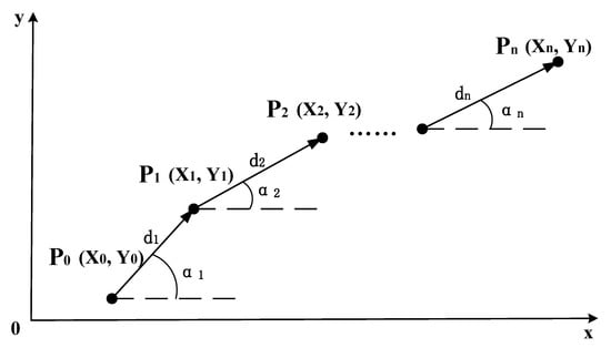
Figure 1. Schematic diagram of the IMU dead reckoning algorithm.
The IMU is usually used as an auxiliary navigation method to assist other positioning methods to estimate the position of the robot. The anti-interference feature of the IMU can be used to correct the positioning information. In recent literature, IMU localization methods focus on how to perform data fusion. The fusion algorithms used are mainly based on filters, but machine learning is also used.
2.2. Visible Light Communication
Localization based on visible light is a new type of localization method. The key element of VLC communication is the LED light [16]. The communication principle is to encode information and transmit the encoded information by adjusting the intensity of the LED, and the photosensitive sensor can receive and decode the high-frequency flickering signal. Using photo sensors to locate the position and orientation of LEDs, the RSSI, TOA, and AOA of radio methods are the main localization techniques [37]. In contrast, a camera can also be used to receive images of LEDs [38]. This approach is similar to Computer Vision.
LED is a kind of energy-saving lighting equipment, which has the characteristics of low energy consumption, long life, environmental protection, and anti-electromagnetic interference. With the popularity of LED lights now, the cost of environmental modification using VLC positioning is lower, which is similar to Wi-Fi. LED lights can be installed in large numbers indoors while considering the functions of lighting and communication. Due to its high-frequency nature, it transmits information without disturbing the illumination [39]. A major disadvantage of VLC is that it can only communicate within the line-of-sight (LOS) range. Moreover, light does not interfere with radio frequency equipment and can be safely used in places where radio frequency signals are prohibited.
The direction of improvement of VLC positioning based on RSSI technology lies in the process of optimizing the signal strength mapping position. An improved Bayesian-based fingerprint algorithm [37], as well as the optimization of a baseline smoother based on an extended Kalman filter and a central difference Kalman, filter have been described [40]. The VLC method can be fused with other localization methods, such as the IMU [16] and the encoder [41], and the corresponding fusion algorithms are the EKF and particle filter. Similar to fingerprint recognition, which requires building a signal strength library in advance, LEDs require a prior calibration stage.
2.3. Infrared Detection Technologies
Infrared is an electromagnetic wave that is invisible to the human eye and has a longer wavelength than visible light. The positioning of indoor mobile robots based on infrared methods relies on artificial landmarks with known positions, which can be divided into active landmarks and passive landmarks according to whether the landmarks require energy or not. The principle of active landmarks is that a mobile robot equipped with an infrared transmitter emits infrared rays and a receiver installed in the environment receives the infrared rays and then calculates the position of the robot, which can achieve sub-meter accuracy. The principle of passive landmarks is that the arrangement in the environment can reflect infrared landmarks and the mobile robot receives the reflected infrared information at the same time and obtains the landmark ID, position and angle, and other information [15]. At present, infrared-based positioning technology is relatively mature, but its penetration is poor, and it can only perform line-of-sight measurement and control. It is susceptible to environmental influences, such as sunlight and lighting, so the application is limited.
The center for life science automation (CELISCA) has developed a complete automatic transportation system for multi-mobile robots across floors [15]. The positioning method was selected by Hagisonic’s StarGazer. It performs indoor positioning based on infrared passive landmarks and obtains the relative position of the robot and passive landmarks through a visual calculation to evaluate the robot’s own position and orientation. The average positioning accuracy is about 2 cm, and the maximum error is within 5 cm. Bernardes et al. designed an infrared-based active localization sensor [48]. Infrared LED lights are arranged on the ceiling, and the mobile robot is equipped with an infrared light receiver. Combined with EKF, the pose of the mobile robot is calculated using the emission angle of the LED.
2.4. Ultrasonic Detection Technologies
An ultrasonic is defined as a sound wave with a vibration frequency higher than 20 kHz, which is higher than the upper limit of human hearing and cannot be heard. At present, ultrasonic ranging has three methods: phase detection, acoustic amplitude detection, and time detection. In practical applications, most of them are time detection methods using the TOF principle. The time detection method obtains the distance by calculating the time when the ultrasonic transmitter transmits the ultrasonic wave and the time difference and sound speed of the ultrasonic wave received by the receiving end [17]. The accuracy can theoretically reach the centimeter level [49]. Among them, the phase detection method has the advantage of better detection accuracy. Its principle is to calculate the measurement distance based on the ultrasonic wavelength by comparing the phase difference when the ultrasonic wave is transmitted and the phase difference when the ultrasonic wave is received. It also has a defect. The measured phase difference is a multiple solution value with a period of 2nπ, so its measurement range needs to be within the wavelength. The acoustic wave amplitude detection method detects the amplitude of the returned acoustic wave, but it is easily affected by factors such as the medium, resulting in inaccurate measurement, but this method is easy to implement. The principle of the transit time detection method is to determine the distance of the obstacle according to the time difference between the ultrasonic transmitting end transmitting the acoustic wave signal and the receiving end receiving the acoustic signal reflected by the obstacle. Although the positioning accuracy of ultrasonic waves can reach the centimeter level in theory, the propagation speed of ultrasonic waves is different in different media. Moreover, it will be affected by changes in temperature and air pressure, and sometimes temperature compensation is required.
2.5. Geomagnetic Field Detection Technologies
The earth is wrapped in a natural geomagnetic field formed between the north and south poles, and the strength of the magnetic field varies with latitude and longitude. At present, geomagnetic fingerprints are mainly used for indoor positioning based on geomagnetism. Magnetic fingerprints have unique properties in space, with geomagnetic modulus values in a small contiguous region forming a fingerprint sequence [54]. Geomagnetic fingerprint positioning includes two stages: offline training and online positioning. During the offline training stage, the geomagnetic sensor is used to collect the geomagnetic information about the sampling points, and the information is stored in the fingerprint information database. In the online positioning stage, the geomagnetic information about the current location obtained by the geomagnetic sensor is used to form the fingerprint information and match the information in the fingerprint database. The geomagnetic field is less affected by external factors, as there is no cumulative error and there is no NLOS problem, but the accuracy is at the meter level. Generally, geomagnetism is used as an auxiliary positioning tool to correct accumulated errors, or used with other sensors for information fusion. The formula for geomagnetic indoor positioning is:
where P is the position of the device is located. B is the measured magnetic field strength at the device’s location. B0 is the magnetic field strength at a reference point. B1 is the magnetic field strength at another reference point.
2.6. LiDAR Detection Technologies
LiDAR systems consist of an optical transmitter, a reflected light detector, and a data processing system. First, the optical transmitter emits discrete laser pulses to the surrounding environment. The laser pulses are reflected after encountering obstacles. The reflected laser light is received by the reflected light detector, and then the data are sent to the data processing system to obtain a two-dimensional image or 3D information of the surrounding environment. LiDAR systems are active systems since they emit laser pulses and detect reflected light. This feature supports the mobile robot to work in a dark environment, does not require any modification of the environment, and is highly universal. In indoor situations, 2D LiDAR is mainstream, and 3D LiDAR is usually used in the field of unmanned driving [56].
The 2D LiDAR SLAM is the mainstream method for the indoor positioning of mobile robots. Without prior information, LiDAR SLAM uses LiDAR as a sensor to obtain surrounding environment data, evaluate its pose, and draw an environment map based on the pose information. Finally, synchronous positioning and map construction are realized. At present, there are two types of 2D LiDAR SLAM methods to solve the indoor positioning problem of mobile robots: filter-based and graph-based [57]. The problem to be solved is the estimation of a posterior probability distribution over the robot’s location given sensor measurements and control inputs. This can be stated as follows:
where xt represents the robot’s state (position and orientation) at time t; z{1:t} represents the lidar observation data from time 1 to t; u{1:t} represents the robot control input from time 1 to t; P(xt|z{1:t},u{1:t}) represents the posterior probability of the robot’s state at time t, given the observation data and control input; P(zt|xt) represents the likelihood probability of observation data zt, given the robot state xt; P(xt|xt−1,ut) represents the transition probability of the current state xt, given the previous state xt−1 and the current control input ut; and η is a normalization factor that ensures the sum of probabilities is 1. By iterating this formula, we can estimate the robot’s position and orientation based on the LiDAR observation data and robot control input.
The filter-based SLAM method has been proposed since the 1990s and has been widely studied and applied [58]. Its principle is simply to use recursive Bayesian estimation to iterate the posterior probability distribution of the robot pose to construct an incremental map and achieve localization. The most basic algorithms are EKF SLAM and particle filter SLAM. Gmapping SLAM and Hector SLAM are now commonly used methods.
EKF SLAM is linearized by first-order Taylor expansion to approximate the nonlinear robot motion model and observation model. Cadena et al. improved the EKF slam based on directional endpoint features [58].
The particle filter RBPF SLAM, also known as sequential Monte Carlo, is a recursive algorithm that implements Bayesian filtering through a non-parametric Monte Carlo method [59,60]. Zhang et al. used the PSO algorithm to improve the particle filter [20]. Nie et al. added loop detection and correction functions [61]. Chen et al. proposed a heuristic Monte Carlo algorithm (HMCA) based on Monte Carlo localization and discrete Hough transform (DHT) [62]. Garrote et al. added reinforcement learning to particle filter-based localization [63]. Yilmaz and Temeltas employed self-adaptive Monte Carlo (SA-MCL) based on an ellipse-based energy model [64]. Based on the EKF and RBPF, FastSLAM combines the advantages of both. It uses a particle filter for path estimation and a Kalman filter for the maintenance of map state variables. FastSLAM has great improvements in computational efficiency and scalability. Yan and Wong integrated particle filter and FastSLAM algorithms to improve the localization operation efficiency [65].
In 2007, Gmapping SLAM was released as open source, which is an important achievement in the field of laser SLAM [66]. It is a particle filter-based method. On this basis, many companies, and researchers have applied Gmapping in mobile robot products [67,68]. Norzam et al. studied the parameters in the Gmapping algorithm [69]. Shaw et al. combined Gmapping and particle swarm optimization [70].
Hector SLAM is also a classic open-source SLAM algorithm based on filtering. The main difference from Gmapping is that it does not require odometer data and can only construct maps based on laser information [71]. Garrote et al. fused mobile Marvelmind beacons and Hector SLAM using PF [72]. Teskeredzic et al. created a low-cost, easily scalable Unmanned Ground Vehicle (UGV) system based on Hector SLAM [73].
The difference between graph-based SLAM and particle filter-based iterative methods is that graph-based SLAM estimates the pose and trajectory of mobile robots entirely based on observational information. All collected data are recorded, and finally, computational mapping is performed [74]. The pose graph represents the motion trajectory of the mobile robot. The pose of the robot is a node of the pose graph, and an edge is formed according to the relationship between the poses. This process of extracting feature points from LiDAR point cloud data is called the front end. The corresponding back end is to further optimize and adjust the edges connected by the node poses, and the optimization is based on the constraint relationship between the poses.
The methods of 2D LiDAR SLAM based on graph optimization include Karto SLAM [75], published by Konolige et al. in 2010, and the Cartographer algorithm, open-sourced by Google in 2016 [76].
Cartographer is currently the best 2D laser SLAM open-source algorithm for mapping performance. Cartographer SLAM uses odometer and IMU data for trajectory estimation. Using the estimated value of the robot’s pose as the initial value, the LiDAR data are matched and the value of the pose estimator is updated. After a frame of radar data is subjected to motion filtering, it is superimposed to form a submap. Finally, all subgraphs are formed into a complete environment map through loop closure detection and back-end optimization [76]. Deng et al. divided the environment into multiple subgraphs, reducing the computational cost of the Cartographer [77]. Sun et al. improved Cartographer’s boundary detection algorithm to reduce cost and error rate [57]. Gao et al. proposed a new graph-optimized SLAM method for orientation endpoint features and polygonal graphs, which experimentally proved to perform better than Gmapping and Karto [78].
LiDAR SLAM cannot provide color information, while vision can provide an informative visual map. Some researchers have integrated laser SLAM and visual SLAM to solve geometrically similar environmental problems, ground material problems, and global localization problems [26,79,80,81,82]. Visual-semantic SLAM maps are built based on laser SLAM maps [83,84]. There is also fusion with other localization methods: odometer [85], Wi-Fi [86,87], IMU [29,30], encoder, RTK, IMU, and UWB [36].
To solve the problem of a large amount of computation in SLAM, Sarker et al. introduced cloud servers into LiDAR SLAM [22]. Li et al. used cloud computing to optimize a Monte Carlo localization algorithm [88]. Recently, some researchers have also performed a lateral comparison between localization methods and algorithms. Rezende et al. compared attitude estimation algorithms based on wheel, vision, and LiDAR odometry, as well as ultra-wideband radio signals, all fused with the IMU [89]. The results strongly suggested that LiDAR has the best accuracy. Shen et al. compared Gmapping, Hector SLAM, and Cartographer SLAM, and the results indicate that Cartographer performs best in complex working environments, Hector SLAM is suitable for working in corridor-type environments, and Gmapping SLAM is most suitable for simple environments [90].
2.7. Computer Vision Detection Technologies
Computer Vision uses cameras to obtain environmental image information. It is designed to recognize and understand content in images/videos to help mobile robots localize. Computer Vision localization methods are divided into beacon-based absolute localization and visual odometry-based SLAM methods. Among them, visual SLAM is a hot spot for the indoor positioning of mobile robots.
Absolute positioning based on beacons is the most direct positioning method. The most common method is the QR code [91,92,93,94,95,96,97]. QR codes can provide location information directly in the video image. By arranging the distribution of QR codes reasonably, the mobile robot can be positioned in the whole working environment. Avgeris et al. designed a cylinder-shaped beacon [98]. Typically, beacons are placed in the environment, and Song et al. innovatively put QR codes on robots and vision cameras mounted on the ceiling [93]. The location of the mobile robot can be determined by tracking the QR code. Lv et al. utilized grids formed by tile joints to assist mobile robot localization [99].
Visual SLAM is similar to LiDAR SLAM. Multiple cameras or stereo cameras are used to collect feature points with depth information in the surrounding environment, and feature point matching is performed to obtain the pose of the mobile robot. Visual SLAM systems use geometric features such as points, lines, and planes as landmarks to build maps. The visual SLAM flowchart is shown in Figure 2 [100].
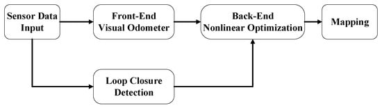
Figure 2. Visual SLAM flowchart.
-
Sensor data input: Environmental data collected by the camera. Occasionally, the IMU is used as a secondary sensor.
-
Front-end visual odometer: Preliminary camera poses estimation based on image information of adjacent video frames.
-
Back-end nonlinear optimization: optimize the camera pose obtained by the front-end to reduce the global error.
-
Loop closure detection: According to the image to determine whether to reach the previous position. Form a closed loop.
-
Mapping: Build a map of the environment based on continuous pose estimates.
Visual SLAM can be divided into five types according to the type of camera: Mono SLAM based on a monocular camera [3,79,87,91,97,99,101,102,103,104,105], Stereo SLAM based on a binocular camera [27,106,107], and RGB-D SLAM based on a depth camera [7,24,25,28,32,80,82,108,109,110,111,112,113,114,115,116,117,118,119,120], fisheye camera [121], and omnidirectional vision sensor [122]. Due to the lack of depth information, monocular cameras are usually used with beacons [91] or IMUs [101]. The algorithm used to fuse the monocular camera and IMUs in visual SLAM is called a visual-inertial odometer (VIO). The current mainstream is RGB-D cameras that can directly obtain depth information. The most common RGB-D camera model in the papers is Kinect, developed by Microsoft.
Currently, many researchers are working on assigning specific meanings to objects in visual SLAM, called semantic SLAM. Semantic SLAM builds maps with semantic entities, which not only contain the spatial structure information of traditional visual SLAM, but also the semantic information of objects in the workspace [123]. It is beneficial to improve the speed of closed-loop detection, establish human–computer interaction, and perform complex tasks.
In semantic SLAM for dynamic scenes, Han and Xi utilized PSPNet to divide video frames into static, latent dynamic, and prior dynamic regions [109]. Zhao et al. proposed to combine semantic segmentation and multi-view geometric constraints to exclude dynamic feature points and only use static feature points for state estimation [101]. Yang et al. introduced a new dynamic feature detection method called semantic and geometric constraints to filter dynamic features [114].
Object detection and recognition based on deep learning is now mainstream in the field of Computer Vision. Lee et al. used YOLOv3 to remove dynamic objects from dynamic environments [124]. Maolanon et al. demonstrated that the YOLOv3 network can be enhanced by using a CNN [21]. Xu and Ma simplified the number of convolutional layers of YOLOv3’s darknet53 to speed up recognition [125]. Zhao et al. used a Mask-RCNN network to detect moving objects [123].
For the division of semantic objects, Rusli et al. used RoomSLAM, which is a method of constructing a room through wall recognition by using the room as a special semantic identifier for loop closure detection [126]. Liang et al. identified house numbers and obtained room division information [84].
With the use of sensor data fusion, more precise positioning can be obtained. Since the previous localization methods have been introduced, they are listed here as LiDAR [79,80,81,83,84,95], IMU [7,24,27,28,97], wheel odometer [99,124], IMU and UWB [32], LiDAR and Odometer [82], LiDAR Odometer and IMU [26], and IMU and wheel odometer [25].
The image information obtained by visual SLAM has the largest amount of data among all positioning technologies. The inability of onboard computers to meet the computational demands of visual SLAM is one of the reasons that currently limits the development of visual SLAM, in particular, deep learning-based visual SLAM [105,107]. Corotan et al. developed a mobile robot system based on Google’s ARcore platform [127]. Zheng et al. built a cloud-based visual SLAM framework [102]. Keyframes are first extracted and submitted to the cloud server, saving bandwidth.
3. Radio Frequency Technologies
Radio frequency-based positioning is a common type of positioning system, covering many fields. It is very convenient to expand from the original communication function to the positioning function, which offers the advantages of low energy consumption and low cost, including Wi-Fi, Bluetooth, ZigBee, RFID, and UWB.
3.1. Radio Frequency Technology Positioning Algorithms
This section introduces several of the classic radio frequency technology positioning algorithms: RSSI, TOA, TDOA, and AOA, as shown in Figure 3.

Figure 3. Radio frequency technologies. (a) TOA; (b) TDOA; (c) AOA; (d) RSSI.
RF positioning algorithms can be divided into two categories according to whether they are based on received signal strength indication (RSSI).
There are two main kinds of positioning techniques based on RSSI: triangulation and fingerprint positioning [128]. The position of the AP (access point) is known by RSSI-based triangulation [129]. The distance between the robot and each AP can be calculated according to the signal attenuation model, and then circles are drawn around each AP according to the obtained distance information. The intersection point is the mobile robot’s position. This method needs to measure the location of the AP in advance, so it is not suitable for situations where the environment is changing.
Fingerprint positioning is more accurate than triangulation. It is divided into two stages, an offline training stage and an online localization stage [130]. In the training phase, the room is divided into small area blocks to establish a series of sampling points, and the radio frequency technology receiving equipment is used to sample these one by one, record the RSSI value and AP address obtained at this point, and establish a database. During online positioning, the mobile robot carries the radio frequency technology signal receiving device, obtains the current RSSI and AP address, and transmits this information to the server to match with the established database to obtain the estimated position. Collecting fingerprints in advance requires significant effort, and the fingerprints need to be re-collected after the signal-receiving device moves.
CSI (Channel State Information) is an upgraded version based on RSSI. The problem of multipath fading is the main problem of RSSI which is difficult to solve but will greatly reduce the positioning accuracy [131]. CSI can receive and transmit channel amplitude and phase responses at different frequencies. In frequency, CSI has fine-grained characteristics compared to the coarse-grained RSSI and has the characteristics of resisting multipath fading [132]. Compared to RSSI, CSI contains more than 10 times the information. Thus, CSI has better stability and positioning accuracy [4]. However, the amount of data transmitted by CSI is huge, which requires more equipment and transmission time.
The positioning methods not based on RSSI mainly include Time of Arrival (TOA), Angle of Arrival (AOA), and Time Difference of Arrival (TDOA) algorithms. These methods are easy to calculate but are generally affected by problems, such as multipath and non-line-of-sight (NLOS) problems of the signal.
The most basic time-based RF positioning method is the Time of Arrival (TOA) [31]. The distance between the two is assessed by recording the time it takes for a signal to travel from the target to the access point (AP). Conventional TOA positioning requires at least three APs with known positions to participate in the measurement. The positioning model can be established according to the triangulation method or geometric formula to solve the target position. The TOA algorithm completely relies on time to calculate the target position and requires exact time synchronization between the target and the AP. The formula for TOA can be described as:
where d is the distance between the transmitter and the device. v is the speed of signals. tr is the time the signal is received by the device. ts is the time the signal is transmitted by the transmitter.
TDOA is a time difference positioning algorithm. It is an improved version based on TOA [133]. The positioning is performed by recording the time difference between the target and different APs to estimate the distance difference between different APs. Like TOA, at least three APs with known locations are required to participate in the measurement. The method selects a base station as a reference base station and combines other base stations and reference base stations to establish multiple hyperbolas with the base station as the focus. The intersection of multiple hyperbolas is the position of the target. The focus of the hyperbolic equation is the base station, and the long axis is the distance between the signal arrival time differences between the base stations. Since there is no need to detect signal transmission time, TDOA does not require time synchronization between the target and the AP; it only requires time synchronization between APs. This feature reduces the need for time synchronization. The formula for TDOA can be described as:
where d is the distance between the transmitter and the device. v is the speed of signals. Δt is the time difference between signals received at two receivers. Δf is the frequency difference between the two signals.
AOA estimates the target position by obtaining the relative angle of the target to the AP [134]. AOA requires at least two APs and sets up array antennas or directional antennas to obtain the angle information of the target and AP. AOA has a simpler structure than the above two algorithms but is seriously affected by non-line-of-sight. The positioning accuracy depends on the accuracy of the antenna array and requires regular inspection and maintenance. The formula for AOA can be described as:
where θ is the angle of arrival of the signal. (x, y) is the position of the device being located. (xs, ys) is the position of the signal source. AOA is a direction-based localization technique that requires multiple antennas or an array of antennas to accurately estimate the angle of arrival.
3.2. Wi-Fi
Wi-Fi is the 802.11 wireless local area network standard defined by the Institute of Electrical and Electronics Engineers (IEEE). The research on Wi-Fi-based indoor positioning started in 2000 [10]. Wi-Fi devices are widely used in various modern indoor occasions, and Wi-Fi is mainly used in mobile robot communication in an indoor environment. It is currently the preferred method in the field of indoor positioning [135]. Wi-Fi-based indoor positioning is relatively simple to deploy in an indoor renovation, and there is no requirement for additional hardware devices. The working frequency of Wi-Fi is in the 2.4 GHz and 5 GHz frequency bands, of which the 5 GHz frequency band has the advantages of less interference, lower noise, and faster speed. The main purpose of Wi-Fi now is communication. If Wi-Fi is to be used for robot positioning, further processing of Wi-Fi signals is required to improve positioning accuracy.
In the screened papers, all the papers based on Wi-Fi technology applied the RSSI technique. While techniques such as TOA and AOA are not uncommon, the RSSI technique has a higher positioning accuracy ceiling. RSSI is less affected by non-line-of-sight and is more suitable for the actual working environment of mobile robots. The problem with RSSI is multipath fading and frequent signal fluctuation. With the introduction of filters, neural networks, and deep learning, there are more and more schemes combined with RSSI. Wang et al. used a K-ELM (Kernel extreme learning machine) to improve the accuracy of a fingerprint recognition algorithm [12]. Cui et al. proposed a robust principal component analysis–extreme learning machine (RPCA-ELM) algorithm based on robust principal component analysis to improve the localization accuracy of mobile robot RSSI fingerprints [136]. Since the fluctuation of Wi-Fi signal strength has a great influence on fingerprint positioning accuracy, Thewan et al. proposed the Weight-Average of the Top-n Populated (WATP) filtering method. Compared with Kalman filtering, it reduces the calculation time while satisfying the positioning accuracy. The Kalman filtering Mean-Square-Error (MSE) is 13.65 dBm, and the proposed method MSE is 0.12 dBm [11]. Sun et al. applied cellular automata to the indoor RSS positioning of AGVs to achieve low-cost filtering of noise caused by environmental factors and mechanical errors [137]. Zhang et al. optimized Wi-Fi-based RSS localization with Deep Fuzzy Forest [138]. The first step in using RSSI is to collect Wi-Fi fingerprints at various indoor locations and establish a database. This step is labor-intensive, and as the location of the device changes, the database needs to be rebuilt. Lee et al. [87] and Zou et al. [86] combined the LiDAR method with the Wi-Fi method and used SLAM technology to collect Wi-Fi fingerprints. CSI and RSSI are compared, and the results indicate that the CSI positioning accuracy error is about 2% smaller than the RSSI, which improves the problem of multipath effects in RSSI [132].
3.3. Bluetooth
Bluetooth uses the 802.15.1 standard developed by the IEEE. The worldwide universal Bluetooth 4.0 protocol was announced in 2010 [139]. Bluetooth communicates using radio waves with frequencies between 2.402 GHz and 2.480 GHz. Among them, the Bluetooth low-energy (BLE) version has the advantages of high speed, low cost, and low power consumption, so it is widely used on the Internet of Things (IoT). Bluetooth positioning technology is mainly based on RSSI positioning. It uses the broadcast function of the Bluetooth beacon to measure the signal strength. A Bluetooth beacon installed in the working environment will continuously send broadcast messages. After the terminal mounted on the mobile robot receives the transmitted signal, it evaluates the pose of the mobile robot according to the positioning algorithm. Bluetooth is widely used in indoor positioning IoT because of its low cost and low operating expenses. Since it is susceptible to noise interference and has insufficient stability, and the positioning accuracy of unprocessed Bluetooth signals is at the meter level, it is rarely used in the field of indoor positioning of mobile robots.
The iBeacon developed by Apple in 2012 and the Eddystone released by Google in 2015 greatly promoted the development of BLE [140]. Although the positioning accuracy of the existing Bluetooth 4.0 technology cannot meet the high-precision requirements of mobile robots, with the emergence of Bluetooth 5.0, this demand can be met. Compared with Bluetooth 4.0, Bluetooth 5.0 has a longer effective distance, a faster data transmission rate, and lower energy consumption [141]. Most importantly, the localization accuracy is improved to the sub-meter level [142]. Bluetooth 5.0 has not been put into formal application, and it is the indoor positioning technology of mobile robots available in the future.
The trend of Bluetooth-based indoor positioning is to combine optimization algorithms with positioning technology. Mankotia et al. implemented a Bluetooth localization of a mobile robot based on iterative trilateration and cuckoo search (CS) algorithm based on a Monte Carlo simulation [143]. Comparing the cuckoo algorithm and particle filter in the simulation, the positioning accuracy of the CS algorithm (mean error 0.265 m) is higher than that of the particle filter (mean error 0.335 m), and the overall error is reduced by 21%.
3.4. ZigBee
ZigBee uses the IEEE 802.15.4 standard specification. Its positioning principle is similar to that of Wi-Fi and Bluetooth, and it is also mainly based on RSSI to estimate the distance between devices. ZigBee is characterized by low cost, wide signal range, high reliability, low data rate, and good topology capabilities. The disadvantage is that the stability is poor, it is susceptible to environmental interference, and the positioning accuracy is at the meter level.
Wang et al. designed a mobile robot positioning system based on the ZigBee positioning technology and combined the centroid method and the least square method to improve the positioning accuracy of the RSSI algorithm in complex indoor environments [144]. The mobile robot is both the coordination node and the mobile node of the network, which increases the mobility and flexibility of the ZigBee network. Since RSSI-based positioning is easily affected by environmental changes, Luo et al. proposed a ZigBee-based adaptive wireless indoor localization system (ILS) in a dynamic environment [128]. The system is divided into two steps. First, the mobile robot uses LiDAR SLAM to collect RSSI values in the working environment and update the fingerprint database in real-time. Secondly, the adaptive signal model fingerprinting (ASMF) algorithm is proposed. The signal attenuation model of the ASMF can reduce noise, evaluate the confidence of RSSI measurement values, and reduce the interference of abnormal RSSI values.
3.5. Radio Frequency Identification
RFID positioning technology uses radio frequency signals to transmit the location of the target. The hardware consists of three parts: a reader, an electronic tag, and an antenna. The reader is the core part of the RFID system, mainly composed of data processing modules. It communicates with the electronic tag through the antenna and reads the information such as ID, RSSI, and phase of the electronic tag [145]. RFID tags are divided into active and passive tags according to whether they need power [146]. Active tags can always transmit wireless signals to the environment, while passive tags are passively responding to the wireless signals emitted by readers. Active tags have wider coverage, but in indoor positioning, passive tags are used more due to their low-cost, easy deployment, and maintenance. RFID has different operating frequencies, mainly including low frequency (LF) (9–135 KHz), high frequency (HF) (13.553–15.567 MHz), and ultra-high frequency (UHF) (860–930 MHz) [147]. At present, UHF-RFID is mostly used in the indoor positioning of mobile robots. Compared with LF and HF, UHF-RFID has the advantages of a simple structure, low cost, and high data transmission rate. Most of the RFID-based papers screened selected UHF-RFID.
Similar to many RF schemes, applying filters to RFID signals is also a common method. DiGiampaolo et al. [148] and Wang et al. [146] both chose Rao-Blackwellized particle filters as the algorithm for RFID SLAM. The reflection and divergence problem of RFID tags is serious. Magnago proposed an Unscented Kalman Filter (UKF) to solve the phase ambiguity of the RF signal backscattered by UHF-RFID tags [149]. Bernardini et al. equipped a mobile robot with dual reader antennas to reduce signal loss and tag backscatter, and used the PSO algorithm to optimize the specific absorption rate (SAR) process [150]. Gareis et al. also used SAR RFID for localization, adding eight channels for monitoring [151]. The positioning accuracy reached the centimeter level. Tzitzis et al. introduced a multi-antenna localization method based on the K-means algorithm [152].
3.6. Ultra-Wide Band
As a carrierless communication technology, a UWB uses non-sinusoidal narrowband pulses with very short periods to transmit data, which can achieve high speed, large-bandwidth, and high time-resolution communication in proximity [153]. Extremely short pulse modulation makes it possible to greatly reduce the effects of multipath problems. Low transmission power avoids interference with Wi-Fi, BLE, or similar devices. A UWB has stronger wall penetration than Wi-Fi and BLE. Recently, the UWB has become the focus in the field of indoor positioning due to its stable performance and centimeter-level positioning accuracy, making it one of the ideal choices for the positioning of mobile robots. High-precision positioning at the centimeter level requires numerous anchor points, higher carrier wave frequency, and sampling frequency, resulting in relatively high hardware and computational costs.
A UWB can achieve localization using RSS, TOA, AOA, and TDOA techniques [154,155,156]. Traditional UWB localization systems are mostly based on mathematical methods and filters [157,158]. Lim et al. proposed a three-layered bidirectional Long Short-term Memory (Bi-LSTM) neural network to optimize UWB localization [159]. Sutera et al. used reinforcement learning to optimize noise in UWB localization and correct localization errors [160]. Recently, data fusion is the trend of UWB positioning. A Constraint Robust Iterate Extended Kalman filter (CRIEKF) algorithm has been proposed by Li and Wang to fuse the UWB and IMU [33]. A Sage-Husa Fuzzy Adaptive Filter (SHFAF) is used to fuse the UWB and IMU [31]. Cano et al. proposed a Kalman filter-based anchor synchronization system to tune clock drift [154]. The UWB has also been used as a hybrid localization method and SLAM method for data fusion using filter algorithms [32,36]. Liu et al. studied how to arrange anchor points scientifically, and proposed a UWB-based multi-base station fusion positioning method [161]. In the actual robot positioning process, the arrangement and rationality of the base station directly determine the positioning accuracy and benign space area.
4. Comparison of 12 Indoor Positioning Technologies for Mobile Robots
A comparison of 12 positioning technologies based on the accuracy, cost, scalability, advantages, and disadvantages of positioning technology is shown in Table 1.
Table 1. Comparison of 12 indoor positioning technologies for mobile robots.
| Technology | Accuracy Level | Hardware Costs | Computational Costs | Advantages | Disadvantages |
|---|---|---|---|---|---|
| IMU | 0.2 m [162] | Low | Low | Wide application Easy to use Anti-interference |
Accumulated error |
| VLC | <0.05 m [44] | Low | Medium | Easy to deploy No electromagnetic interference |
Only line-of-sight communication |
| Ultrasonic | 0.012 m [49] | Low | Low | Mature technology High positioning accuracy |
Short-distance measurement Signal attenuation |
| IR | <0.1 m [48] | Medium | Low | Mature technology | Only line-of-sight communication Need environmental transformation Affected by sunlight |
| Geomagnetic | <0.21 m [55] | Low | Low | No cumulative error No need for environmental transformation |
Low accuracy Build a geomagnetic database |
| LiDAR | <0.025 m [90] | High | High | Strong adaptability Strong stability No need for environmental transformation |
High requirements for algorithms Affected by glass objects Suffer in weak feature environments |
| Computer Vision | 0.09 m [108] | Medium | High | Collection of rich information Strong adaptability No need for environmental transformation |
High requirements for algorithms and computing performance Affected by light Suffer in weak feature environments |
| Wi-Fi | 2.31 m [136] | Medium | Medium | Widely used Mature technology Easy to deploy |
Easy to be interfered with Multipath problem |
| Bluetooth | 0.27 m [143] | Low | Low | Wide application Low-power consumption |
Path loss Easy to be interfered with |
| ZigBee | 0.71 m [128] | Low | Low | Low-power consumption Good topology |
Poor stability Easy to be interfered with |
| RFID | <0.01 m [150] | Low | Low | High positioning accuracy Easy to deploy |
Need environmental transformation Multipath problem |
| UWB | <0.1 m [161] | High | Medium | High positioning accuracy Anti-interference High multipath resolution |
High cost |
The accuracy level column shows the data with the highest accuracy of the corresponding method in the literature. The hardware and computational cost may vary depending on the specific implementation, the environment, and other factors. This table is only intended to provide a rough comparison of the relative costs of different indoor localization techniques. The cost considered here refers to the expenses required to implement high-precision positioning solutions for this type of technology.
This entry is adapted from the peer-reviewed paper 10.3390/robotics12020047
This entry is offline, you can click here to edit this entry!